Electronics Production
For this assigment, we have to:
- (DONE) Make an in-circuit programmer by milling the PCB (program it, so that you can use it to program your board in Electronics Design week, and in other weeks).
- Optionally, trying other processes.
All the files created for this assigment can be found on the link bellow:
---> DOWNLOAD FILES<---
Have you:
- Shown how you made and programmed the board?
--> yes
- Explained any problems and how you fixed them?
--> yes
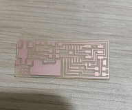
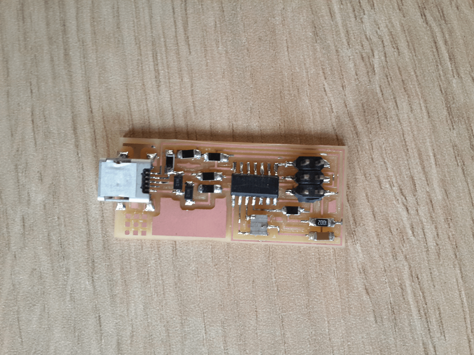
- Included a ‘hero shot’ of your board?
--> yes
Working With The Milling Machine
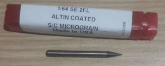
For this task, we are going to work with two end mills of different sizes: The first one is a 1/64'' end mill for making the traces and the second one is a 1/32'' end mill for cutting the limits of the circuit.
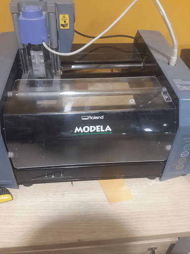
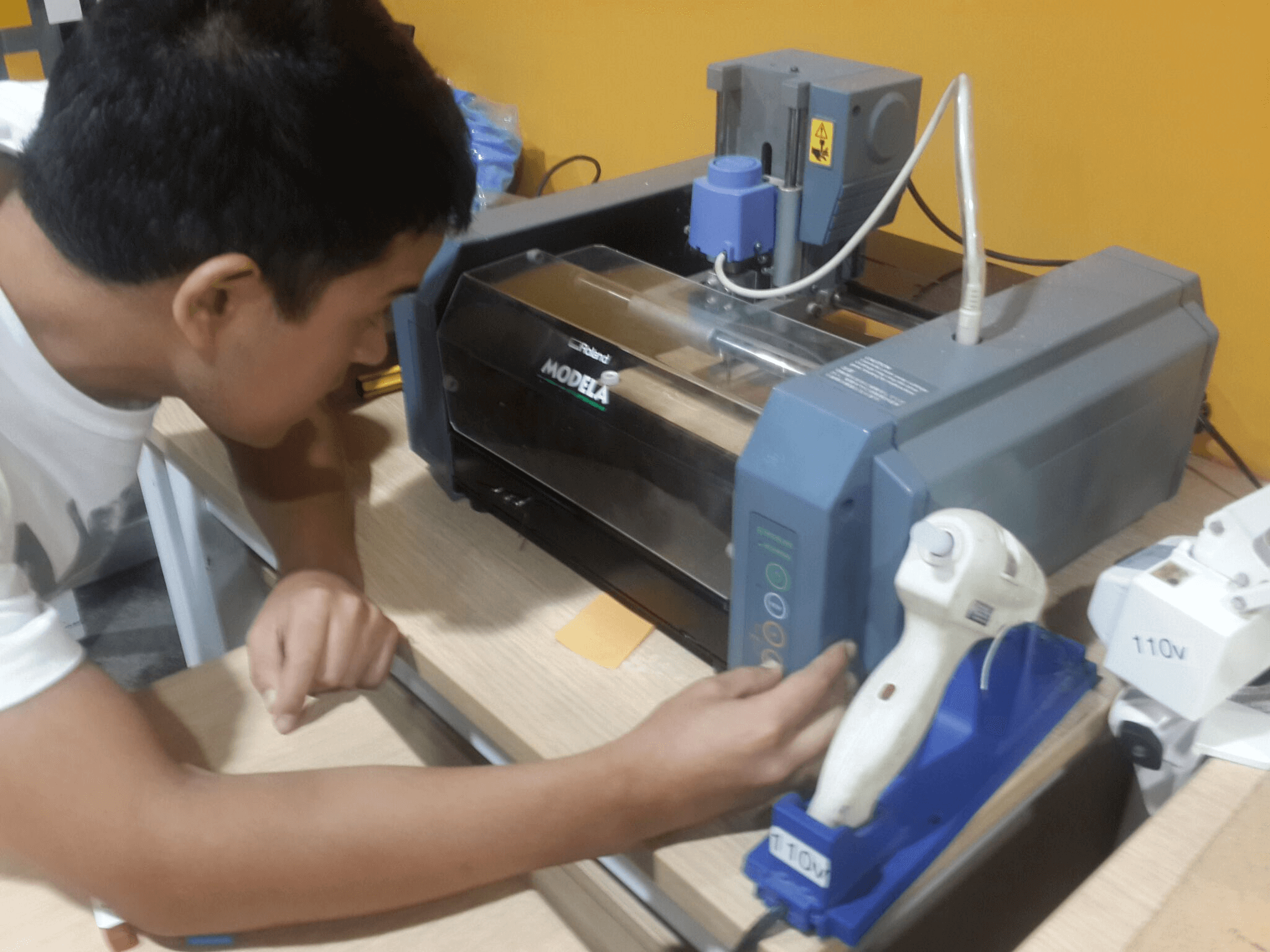
The milling machine we are going to work with is the MDX-20.
For working with this machine we have to follow a series of steps:
1. First connect the milling machine to your pc and turn it on. It will start in the view mode (this means that its platform is going to be close to you so that you can extract or put a pcb over it).
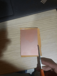
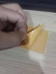
2. Tape the back of the circuit with a double side tape and stick it to the milling machine platform, press it against the platform and make sure it does not move (if it moves the end mill will break when the machine starts to mill).
3. Press the view button to retire the view mode. The platform is going to move toward the back side.
4. Unlock the two locks in the chuck with a drill wrench and insert the 1/64'' end mill inside of it, so that half of it stays free, then lock it again.
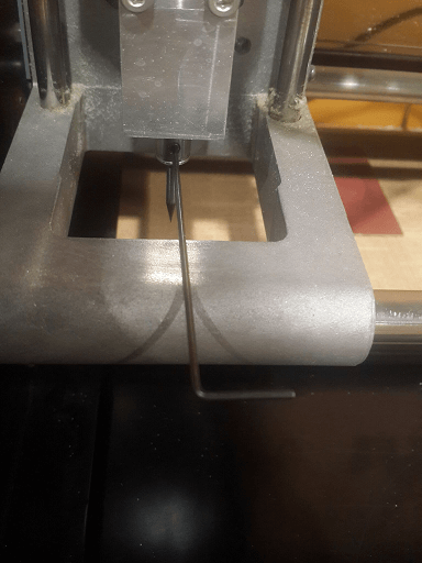
By the way, the first time I tried to mill the circuit, I broke the end-mill. This happened because I did not fixed the end-mill very well, so on my second try I turned the secures as hard as I could and I did not had any problem when milling.
5. Put the milling machine cover
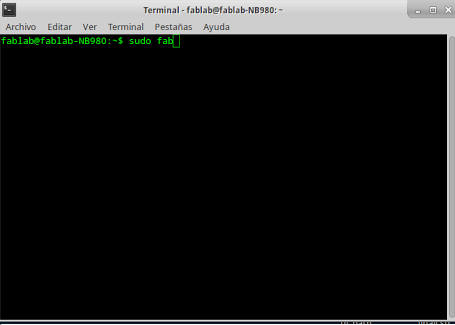
6. Open a linux terminal and type "sudo fab". Sudo is for getting root permissions on the pc and fab is the program that we are going to use.
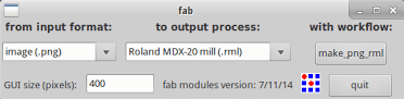
7. Once the program is open, select the extension of the image that is going to be loaded as .png and select the machine as Roland MDX-20 mill.
8. Load the image that contains the circuit traces.
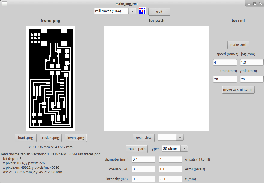
9. Set the min max position with the position coordinates of the circuit with respect to the origin coordinates of the platform (on the botton left) and add them 1 mm to each coordinate to ensure that the cutter mill is going to be over the circuit.
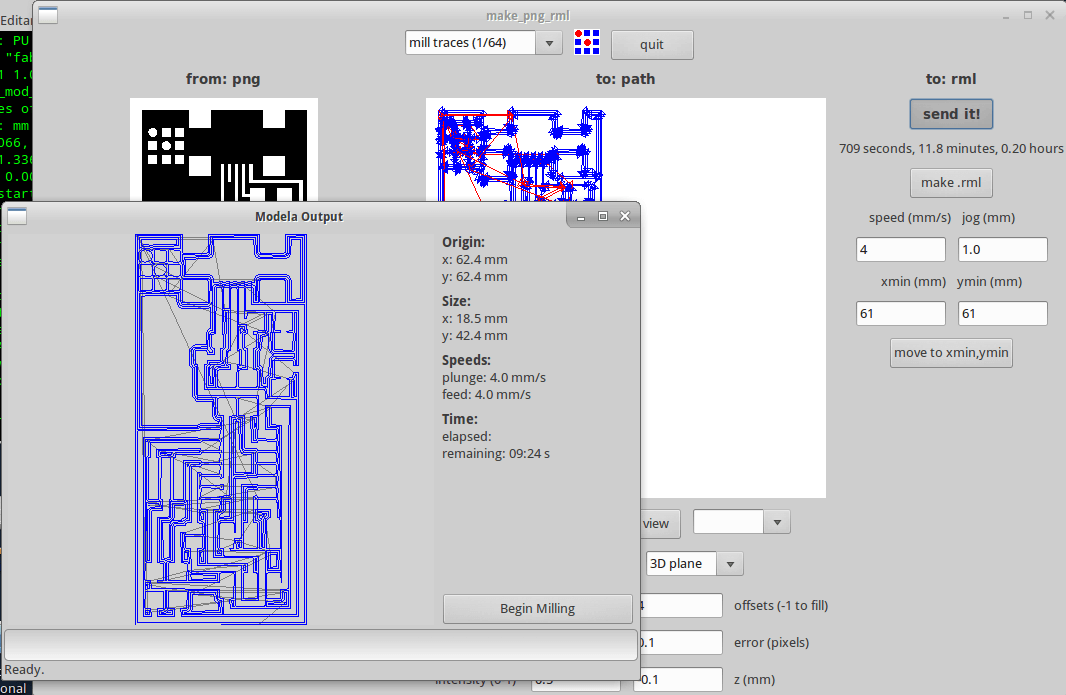
10. Select the operation to execute as "mill traces (1/64)", and the error on 0.1 pixels and left the rest of default parameters unmodified
11. Then press make path to get the trayectory of the the end mill
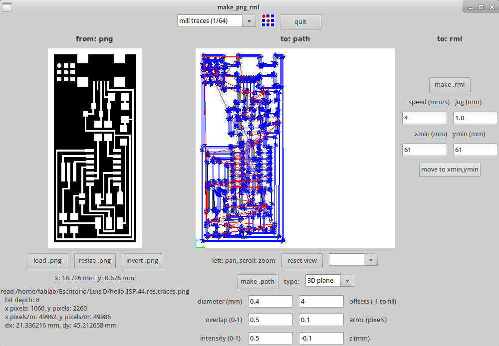
12. Press the min max button, and the end mill will move to the specified position.
13. Then manually aproximate the end mill to the circuit by pressing the down button on the milling machine until the the end mill slightly touches the pcb.
14. Press make_rml and then send it!. A window will appear indicating the state of the process.
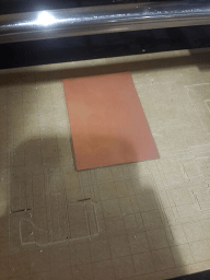
15. Once the process finishes, press the view mode, retire the cover and remove the exceeding material.
16. Reset the machine min-max position by turning off and on the milling machine.
17. Change the 1/64'' end mill by a 1/32'' end mill and put the cover.
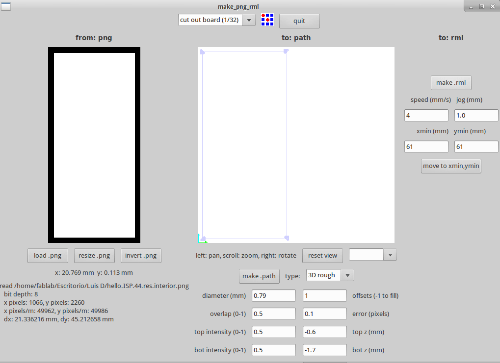
18. Load the image that delimits the circuit borders.
19. Change the operation to "cut out board (1/32)" and press make.path to get the cutter path.
20. Press the min max button and then manually approach the the circuit to the board by pressing the down button until it slightly touches it.
21. Press make.rml and the send it!. A window will appear indicating the state of the process.
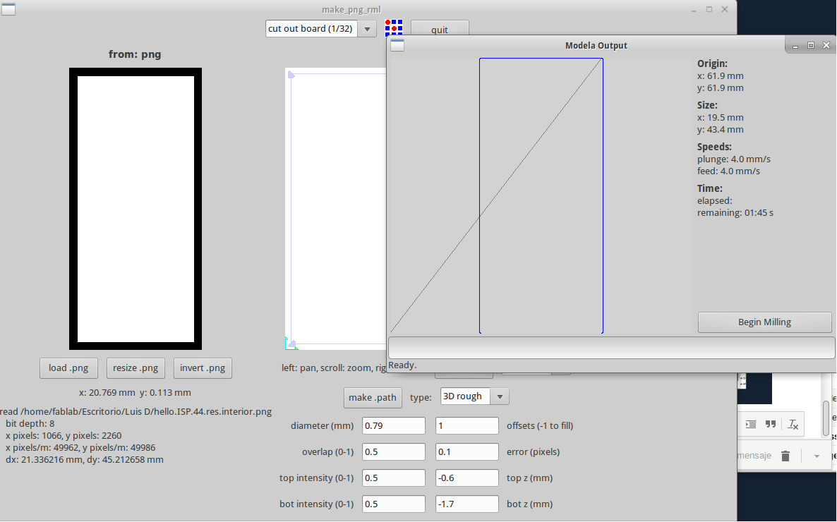
22. Once it finishes, retire the cover, remove the exceeding material and take out the circuit.
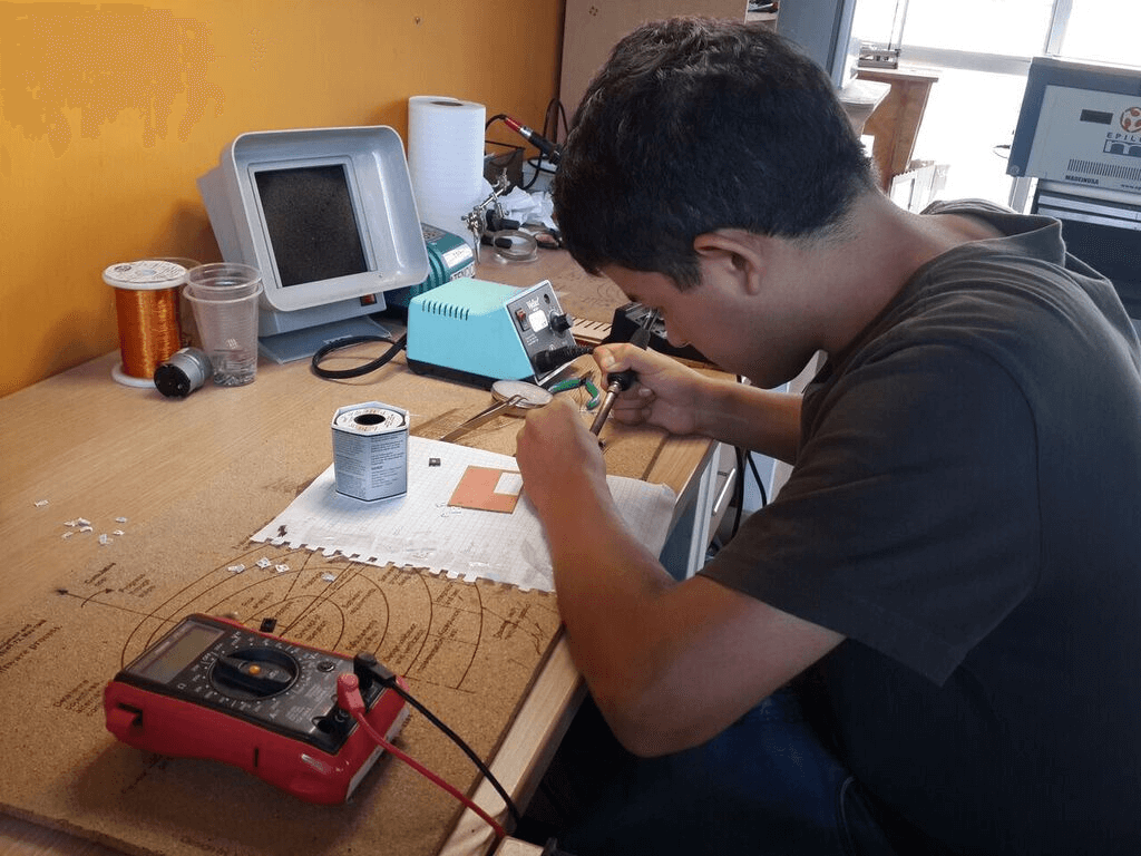
Soldering The Circuit Components
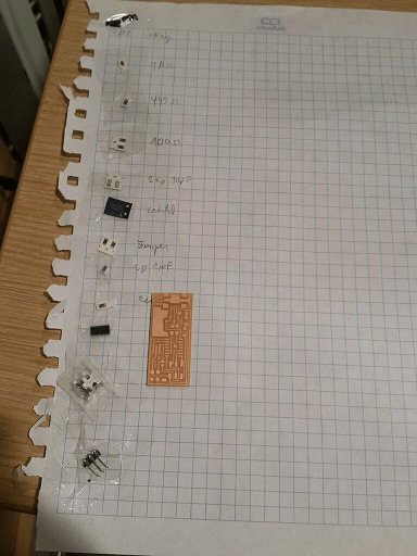
Before soldering the circuit components, its a good idea to label them all, since most smd components look similar.
There are some simple steps one can follow to solder smd components:
1. Clean the soldering iron tip.
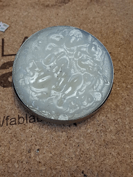
2. Put the tip inside a soldering paste for a couple of senconds. This avoids that the welding sticks to the tip.
3. Put the tip of a soldering wire over a pad.
4. Heat the pad, not the wire, with the soldering iron.
5. Wait until the wire melts over the pad.
6. Take a component with a couple of tweezers and put one of its pins over the melted wire.
7. By now, the welding must be solid, so press the component pin towards the pad and heat it with the iron solder until the weld melts again.
8. Retire the soldering iron, wait a little bit and then open the tweezers.
9. Now the components must be fixed to the PCB. So without the tweezers, put the soldering wire over another pin of the component and heat it with the soldering iron until it melts over another pad.
10 With the aid of a multimeter, verify continuity for each component pin, by putting one of the tester tips on a path connected to the soldered pin and the other tip over the soldered pin.
11. Go for the next component and repeat the steps from 1 to 10.
Doing My Own ISP Programer
For uploading the firmware into the circuit we can follow the next steps:
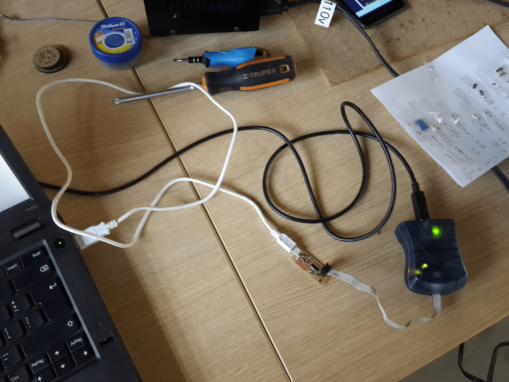
1. Power the circuit with a USB cable.
2. Connect the circuit ISP connector to a ISP programmer.
3. Download the ISP firmware from here.
4. Open a terminal and go to the firmware directory.
5. Type make clean, to clean previous builds.
6. Type make hex, to create an hexadecimal build of the firmware.
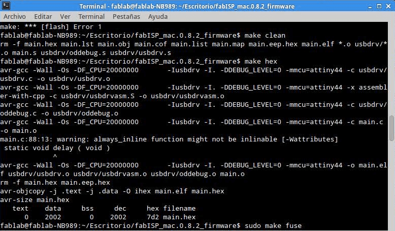
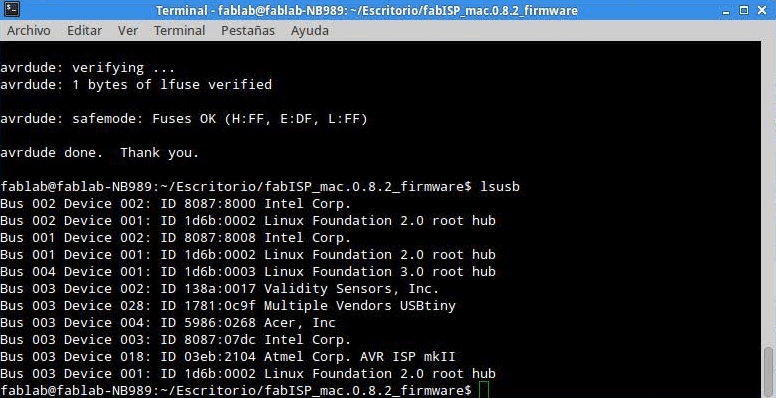
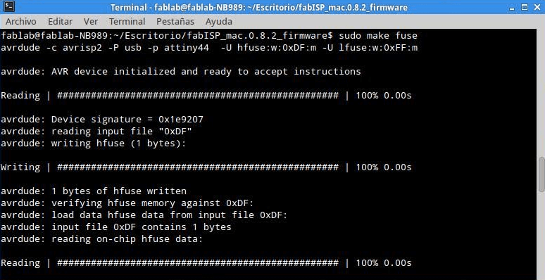
7. Type sudo make fuse, to flash the fuse.
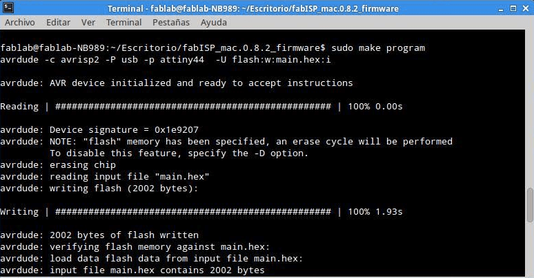
8. Type sudo make program, to flash the firmware and the fuse.
9. Type lsusb, to verify that the files are stored in the microcontroller.