MailPlus
"MailBox with an Accent"
Being sometimes an absent-minded person, some years ago my physical mailbox got full and some important mail went lost. Since then, I was unsuccessfully looking for a Smart MailBox, able to interact with me and give some advice about its state. Being now a Fab Academy student, the first idea that came to my mind while thinking about the "final-project", was to build such a MailBox; this is going to be a Smart Mailbox that digitally interacts with it's owner; it will have a sensor (Hall Effect Sensor) and three sensors (Green, Yellow, Red LEDs -and maybe someday also radio) to tell the owner if new mail is (potentially) in: here it comes MailPlus! :)
First of all, as requested by Neal during this the very last lecture on Wednesday June 7th, about evaluating Final Project it's important to have in mind clear answers about some key questions, like
What is the deadline? How much time do I have left?
Deadline for MailPlus Final Project was on June 19th, the day I was scheduled for my Final Project Presentation with Neal, instructors, and the class.
Even if created some MailPlus Final Project parts during this year Fab Academy Weeks (e.g. mail sticker on Week 03, door hinges on Week 09, brand/logo on Week 18) I basically began to work "full-steam" at project development on the last three weeks before the given deadline: as I already said on Week 17 assignment, project development was basically divided over the span of three weeks, following this timetable:
- Week 1: main container production => May 29th - June 4th
- Week 2: mechanical assembly and testing of moving parts => June 5th - June 11th
- Week 3: electronics and stickers => June 12th - June 18th
What tasks have been completed? And what tasks remain?
Being, after all, a not-so-complex project (it was, indeed, in some ways difficult for me), I managed to complete all tasks in time (see timetable reported on previous section). A future task will be adding some more outputs (e.g. a radio module) and a web-based software user interface.What has worked? What hasn’t?
I would say pretty much everything worked fine; I was very happy about final result, and -as said during my Final Project Presentation since I was asked by Neal and Neal himself repeated to us that "Final Projects have to survive to Final Presentations"- I'm planning to use this mailbox for my personal use at home, and maybe build a second more evolved prototype to be used as mailbox at Crunchlab; the main concern I have about this it's only that MailBox have to stand outside, therefore resist to weather agents (I'm considering to add some water-based, protective impregnating coating for wood; and also some humidity protection for the electronics) and to some people -maybe wanting to vandalize the box just for the sake of it.What questions still need to be resolved?
I still have a small issue with the electronic part: seldom random failures on Hall effect sensor readings; I'm further investigating this issue: at the moment I believe the problem it's probably due to magnet dimensions and/or position and/or round shape.What have you learned?
From Final Project experience I learned lots of things, but one in particular over the others: mastering single skills it's not like mastering all-of-them integration; in some way's, I would say that integration is a skill itself: maybe the most important.Project Development
Here we come at MailPlus Project Development, with some documentation about it. From first concept sketches designed with GIMP on Week 02

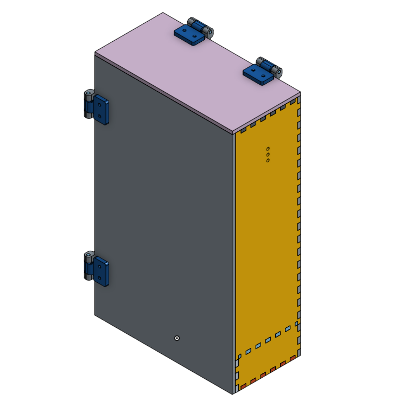
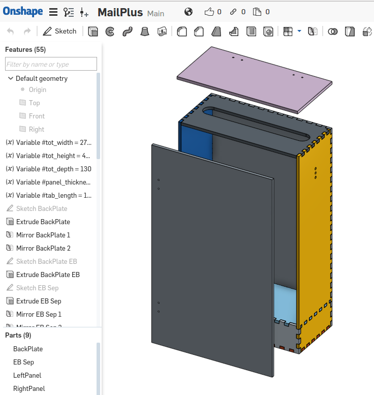
...and first 3D design concept. For 3D design I used Onshape cloud 3D modeling software...
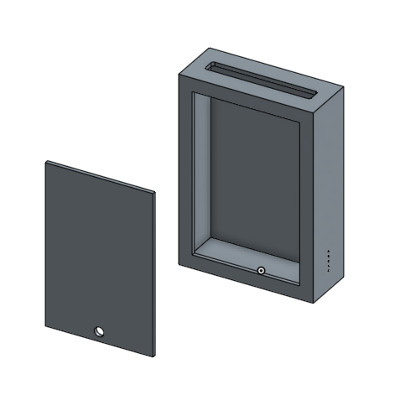
...I designed the final 3D model, from which I obtained DXF files of faces to be lasercutted
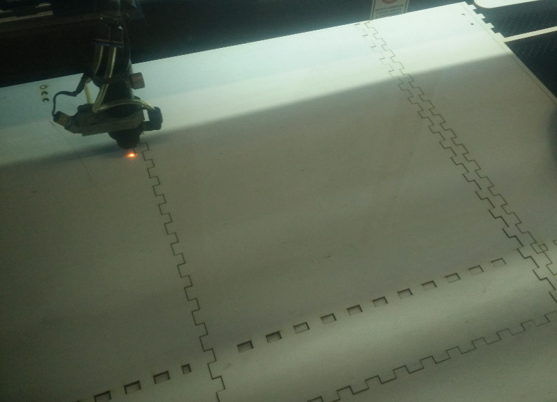
...lasercutting (and engraving) /1 (TOP Plane) I used 6mm thick sheets of poplar plywood with a water-based glue
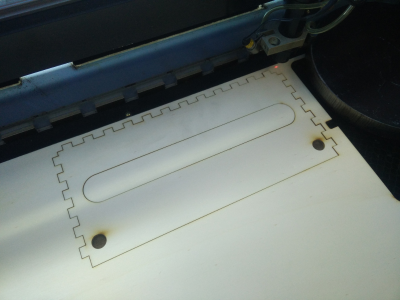
...lasercutting /2
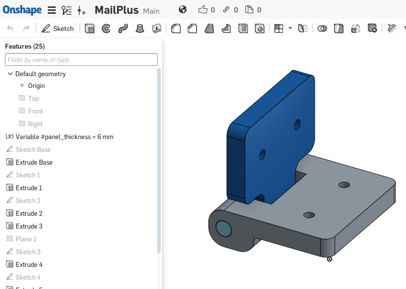
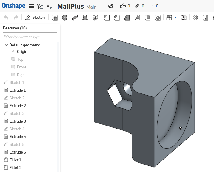
...creating hinges /1 (3D-design)
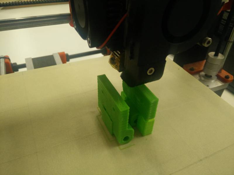
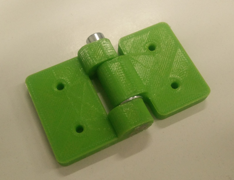
...creating hinges /2 (3D-print) I used 1.75mm PLA filament
...creating hinges /3 (assembling) To keep hinges together I used 3mm stainless steel screws
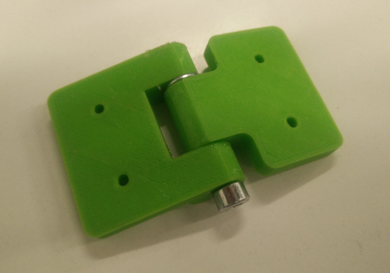
...creating hinges /4 (upper view)
...creating magnetic locks /1 (3D design)
...creating magnetic locks /2 (assembly testing)
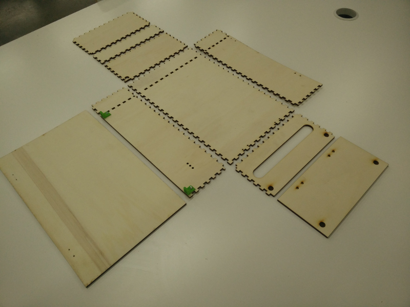
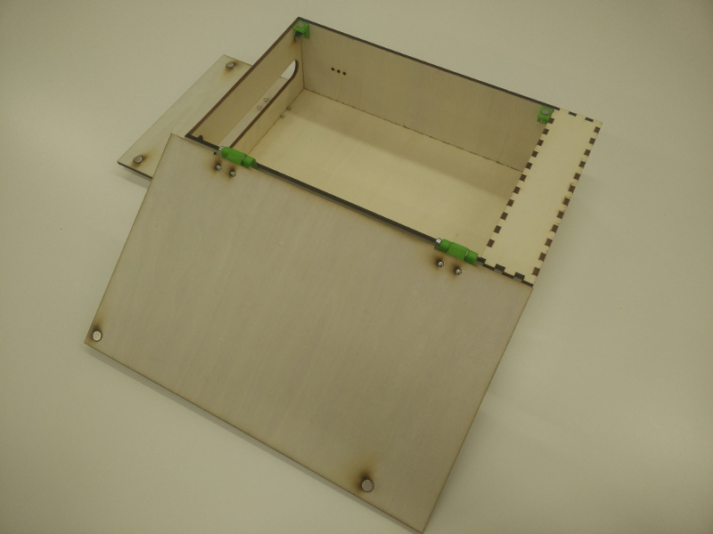
...box assembly /1 (parts layout) To keep wooden parts together I used vynilic glue
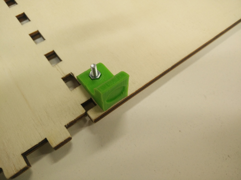
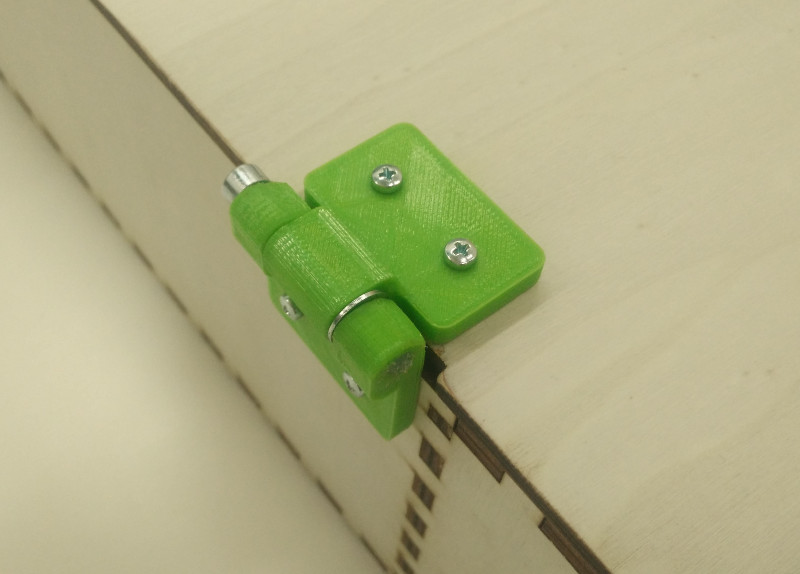
...box assembly /2 (installing hinges) To keep PLA parts together with plywood I used 3mm stainless screws
...box assembly /3 (installing hinges -detail)
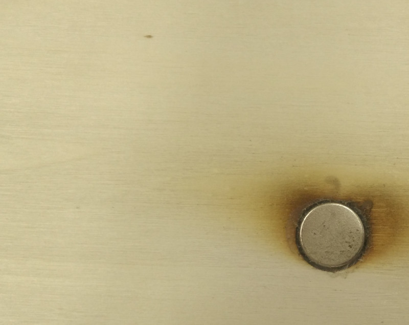
...box assembly /4 (installing magnets on doors) To keep magnets in place I used acrylic glue; also, engraving got plywood a little overburned this time, next time I'm going to use less power
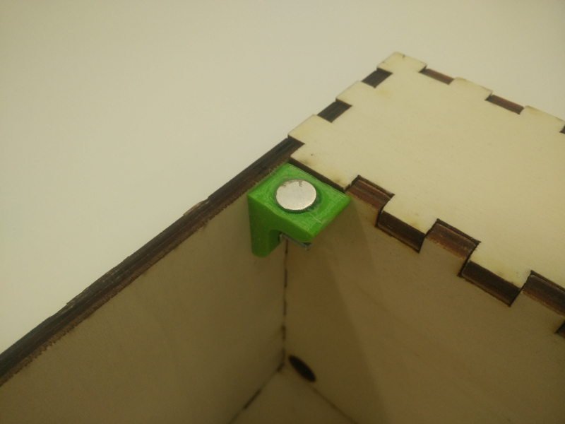
...box assembly /5 (installing magnets on locks) To keep magnet in place I used acrylic glue
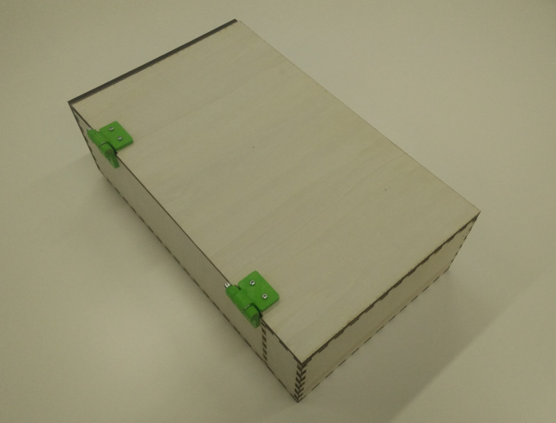
...box assembly /6 (general view)
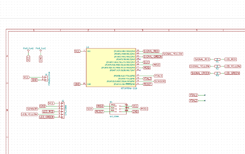
...creating microcontroller board /1 (board design -schema) for electronics design I used KiCAD EDA software; as microcontroller I used ATtiny 84A-SSU
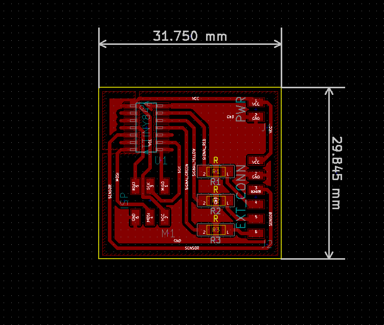
...creating microcontroller board /2 (board design -manually routing traces)
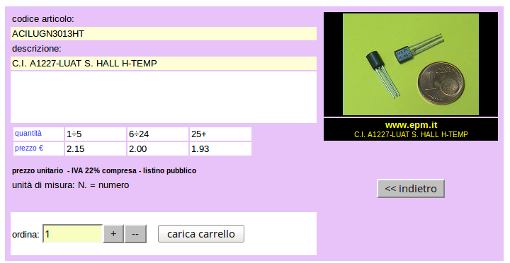
...creating microcontroller board /3 -To tell if top door is open or closed I used, as suggested to me by Neal during weekly reviews, an Hall-effect sensor (A1302 from Allegro Microsystems LLC)
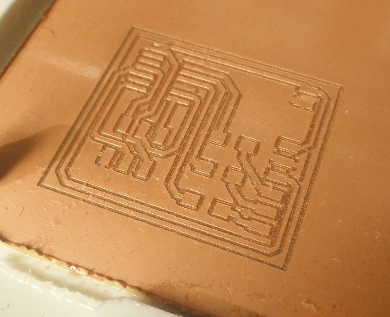
...creating microcontroller board /4 (milling board from FR-1 sheets)
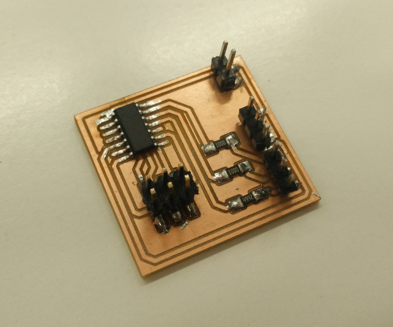
...creating microcontroller board /5 (stuffing board)
Time to programming board! As usual for me, I programmed the board writing the code through Arduino IDE software; sensor tells microcontroller if door is open or not: if open changes LEDs status lightin up different LEDs: from green, to yellow, to red; I also programmed a special reset sequence, to bring back light to green when mail has been collected; here's the full code:
////////////////
// Setup vars //
////////////////

// Pin controlling the green light
int gled = 2;
// Pin controlling the green light
int yled = 1;
// Pin controlling the green light
int rled = 0;
// Pin reading hall sensor output (Allegro A1302)
int hall = 8;

byte mail_status = 0;


////////////////////
// setup function //
////////////////////
void setup() {
    // Serial initialization
    //Serial.begin(9600);
    // Setting up the I/O pins
    pinMode(gled, OUTPUT);
    pinMode(yled, OUTPUT);
    pinMode(rled, OUTPUT);
    pinMode(hall, INPUT);
}


///////////////////
// loop function //
///////////////////
void loop() {
    boolean hallState = digitalRead(hall);
    //Serial.println(hallState);
    switch (mail_status) {
        case 0:
            if (hallState == HIGH) {
                mail_status = 1;
            }
            break;
        case 1:
            if (hallState == LOW) {
                mail_status = 2;
            }
            break;
        case 2:
            if (hallState == HIGH) {
                mail_status = resetStatus();
            }
            break;
    }

    displayStatus(mail_status);
    delay(500);

}

////////////////////////////
// displayStatus function //
////////////////////////////
byte resetStatus() {
    int counter_a = 0;
    int counter_b = 0;
    int counter_c = 0;
    int delaytime = 5000;

    //Serial.print("resetting: ");
    digitalWrite(yled, HIGH);
    boolean hallState = digitalRead(hall);

    while (hallState == HIGH) {
        hallState = digitalRead(hall);

        if (counter_a == delaytime+1) {
            digitalWrite(gled, HIGH);
        }
        if (counter_a == delaytime*2) {
            digitalWrite(gled, LOW);
            //Serial.println("no");
            digitalWrite(yled, LOW);
            delay(delaytime*2);
            return 2;
        }
        while (hallState == LOW && counter_a > delaytime && counter_a <= delaytime*2) {
            hallState = digitalRead(hall);

            if (counter_b == 0) {
                digitalWrite(gled, LOW);
            }
            if (counter_b == delaytime+1) {
                digitalWrite(gled, HIGH);
            }
            if (counter_b == delaytime*2) {
                digitalWrite(gled, LOW);
                //Serial.println("no");
                digitalWrite(yled, LOW);
                delay(delaytime*2);
                return 2;
            }
            while (hallState == HIGH && counter_b > delaytime && counter_b <= delaytime*2) {
                hallState = digitalRead(hall);

                if (counter_c == 0) {
                    digitalWrite(gled, LOW);
                }
                if (counter_c == 501) {
                    digitalWrite(gled, HIGH);
                }
                if (counter_c == 2000) {
                    digitalWrite(gled, LOW);
                    //Serial.println("no");
                    digitalWrite(yled, LOW);
                    delay(delaytime*2);
                    return 2;
                }
                if (hallState == LOW && counter_c > delaytime/10 && counter_c <= delaytime/2) {
                    //Serial.println("yep");
                    digitalWrite(yled, LOW);
                    return 0;
                }
                counter_c++;
                delay(1);
            }
            counter_b++;
            delay(1);
        }
        counter_a++;
        delay(1);
    }
    //Serial.println("no");
    digitalWrite(yled, LOW);
    return 2;
}

////////////////////////////
// displayStatus function //
////////////////////////////
void displayStatus(byte led_status) {
    switch (led_status) {
        case 0:
            digitalWrite(gled, HIGH);
            digitalWrite(yled, LOW);
            digitalWrite(rled, LOW);
            //Serial.println("green");
            break;
        case 1:
            digitalWrite(gled, LOW);
            digitalWrite(yled, HIGH);
            digitalWrite(rled, LOW);
            //Serial.println("yellow");
            break;
        case 2:
            digitalWrite(gled, LOW);
            digitalWrite(yled, LOW);
            digitalWrite(rled, HIGH);
            //Serial.println("red");
            break;
    }
}
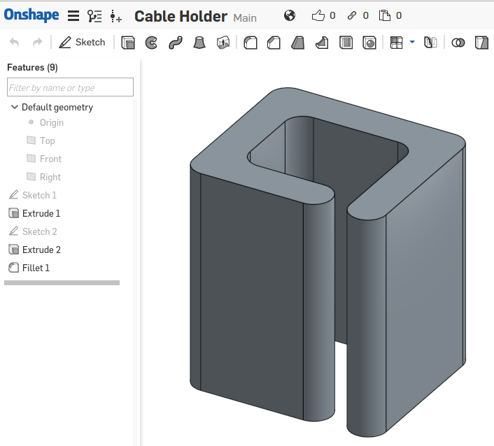
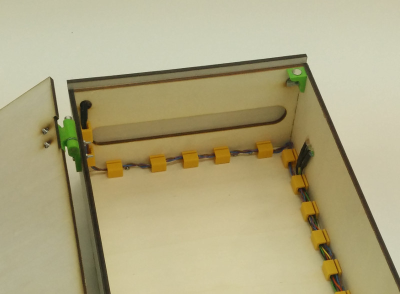
To make MailPlus a more finished product from the inside -as suggested by Neal- and not just a "bunch of cables", I decided to create my own cable-holders; from 3D design...
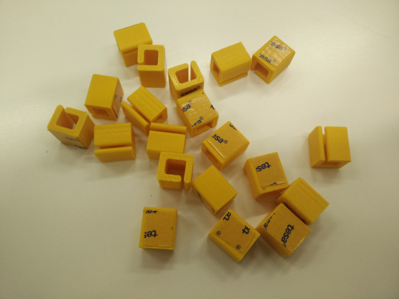
...to "mass" production! :)
Here's it's how it looks the inside...
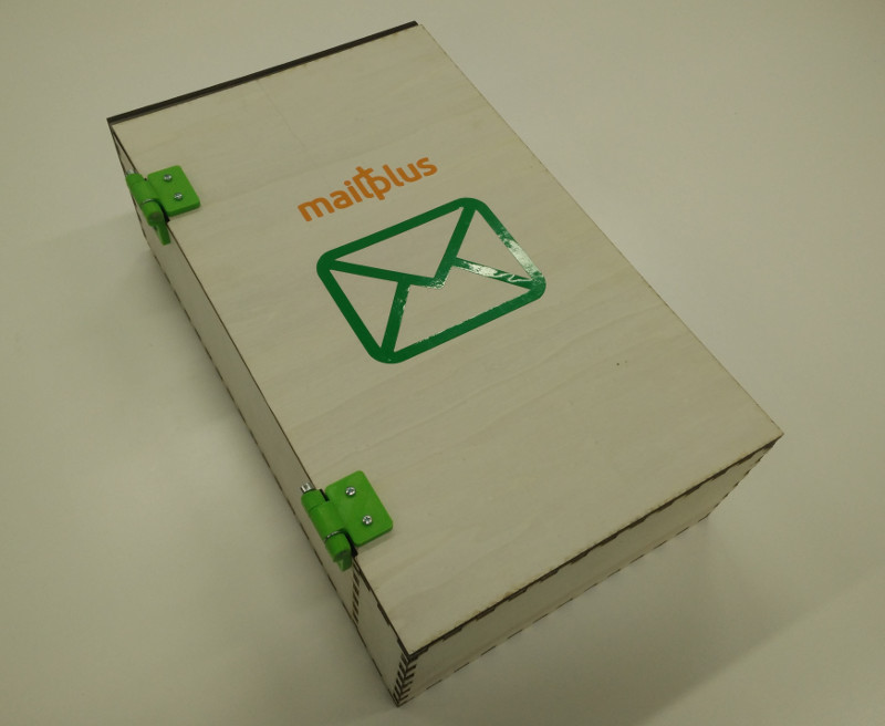
...and here's it's how it looks the outside; vinyl stickers (mail icon, and brand/logo) have been machine-cutted with Inkscape plugin for Silhouette Cameo machine as shown in Week 03
I'm very happy with final result! As it's possible to see from presentation video it also works very well.
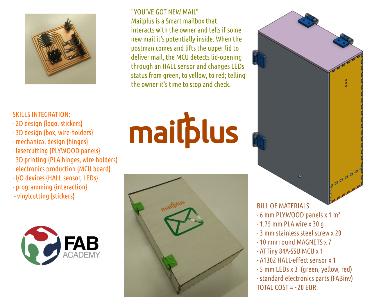
Project Presentation
Here's Presentation Slide
and here it is, the Final Project "Super Hero Shot" Video
Source files
- mailplus.sldprt -Onshape output SLPRT File (MailPlus)
- mailplus-hinge-A.sldprt -Onshape output SLPRT File (Hinge -Part A)
- mailplus-hinge-A.stl -Onshape output STL File (Hinge -Part A)
- mailplus-hinge-B.sldprt -Onshape output SLPRT File (Hinge -Part B)
- mailplus-hinge-B.stl -Onshape output STL File (Hinge -Part B)
- mailplus-lock.sldprt -Onshape output SLPRT File (Lock)
- mailplus-lock.stl -Onshape output STL File (Lock)
- mailplus-cholder.sldprt -Onshape output SLPRT File (Cable Holder)
- mailplus-cholder.stl -Onshape output STL File (Cable Holder)
- mailplus.sch -KiCAD Eeschema output SCH File
- mailplus.net -KiCAD Eeschema output NET File (Netlist)
- mailplus.kicad_pcb -KiCAD PcbNew output KICAD_PCB File
- mailplus-F.Cu.svg -KiCAD PcbNew output SVG File (Traces)
- mailplus-F.Cu.png -Inkscape output PNG File (Traces)
- mailplus-Edge.Cuts.svg -KiCAD PcbNew output SVG File (Edge)
- mailplus-Edge.Cuts.png -Inkscape output PNG File (Edge)
- mailplus.ino -Arduino IDE output INO File
- mailplus.svg -Inkscape output SVG File (Logo/Brand)