Week 03
Computer Controlled Cutting
The third lecture on Wednesday February 8th was about Computer Controlled Cutting: different ways and tools to cut materials. Assignment given by Neil for this third week was:
- Make lasercutter test parts varying cutting settings and slot dimensions
- Cut something on the vinylcutter
- Design, make, and document a parametric press-fit construction kit, accounting for the lasercutter kerf, which can be assembled in multiple ways
Lasercutting test parts
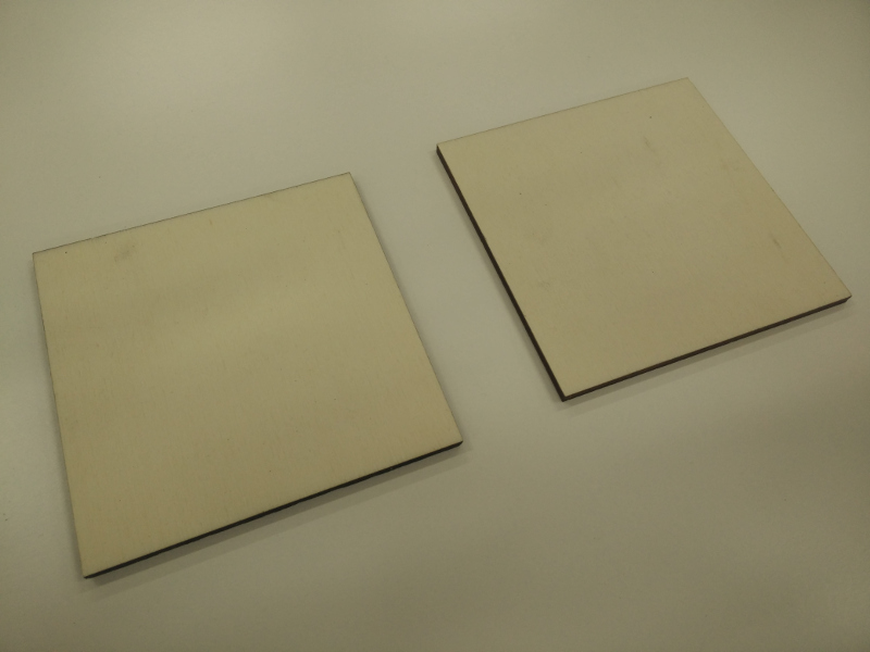
As suggested by guru instructor Fiore Basile during italian local review, I'm going to cut a simple model (thinking about a simple square) at different powers and speeds, to see and evaluate different details, especially laser kerf. So I tried to cut two 4mm plywood (poplar plywood with a waterbased glue) square parts from the same drawing (100mm side length) but with different cutting Power and Speed
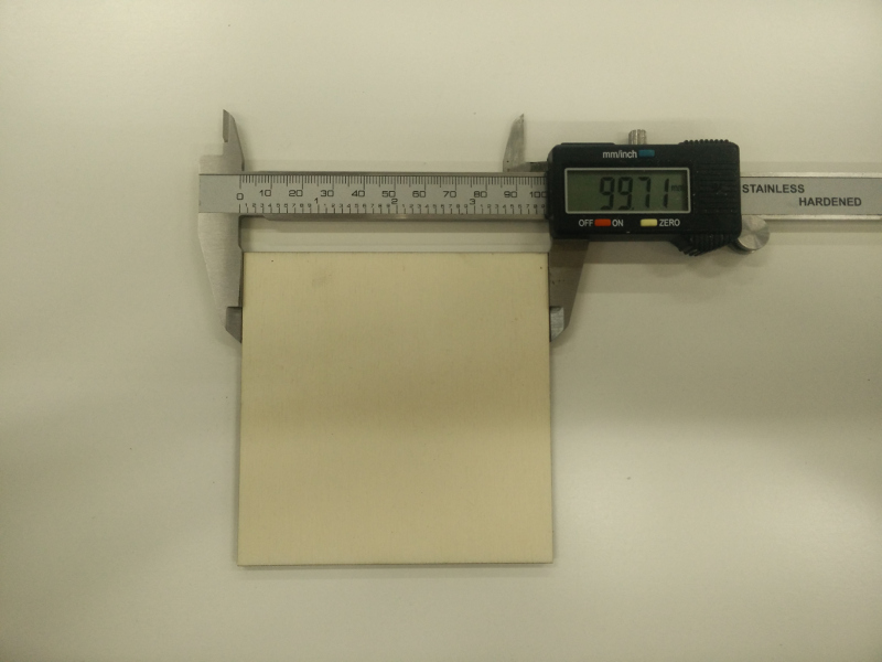
This part was made with 10W Power (out of 40W max Power) and 2.5 mm/s Speed -in this case laser kerf is 0.145 mm =(100-99.71)/2, and the border is dark
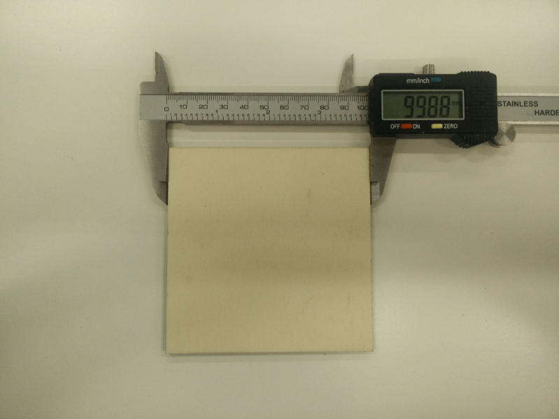
This part was made with 40W Power (maximum) and 20.0 mm/s Speed -in this case laser kerf is 0.06 mm =(100-99.88)/2, and the border is much less burned-out
Vinylcutting
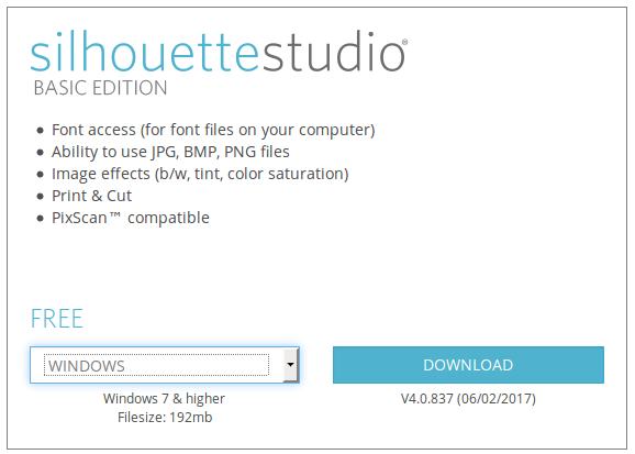
About this week's vinylcutting assignment, I got committed to produce a good output vynil sticker decoration for my Final Project through a Silhouette Cameo 3 machine from Graphtec; this machine comes with Silhouette Studio software, which is only supported for Windows and MAC systems and it's proprietary software itself; I was not very happy about this, because -as far as I can- I prefer using a Free Software and a GNU/Linux system
Anyway, after a lot of websearch and different tryouts, I managed to drive the machine from a GNU/Linux system through the great inkscape-silhouette Inkscape python plugin by Fablab Nuernberg. Getting this plugin working on a Mint GNU/Linux system distribution -supposing Inkscape software is already installed on the given system- it's easy as installing python-usb USB interface for Python modules from a terminal console with super-user privileges
~ $ apt-get install python-usb
then installing the given pre-compiled package
~ $ apt-get install inkscape-silhouette_1.19-1_all.deb
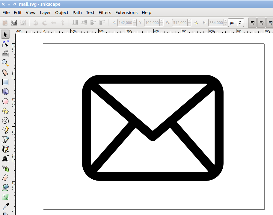
At this point I opened Inkscape and designed a mail sticker
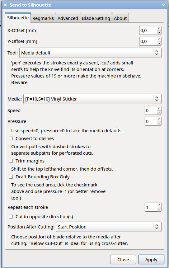
then I went to inkscape-silhouette plugin (Extensions => Export => Send to Silhouette... ); this opens a dialog window from which it's possible to define cut settings, the most important being:
- Tool (Pen, Cut)
- Media Type -hence Pressure and Speed
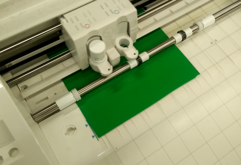
then I positioned the vynil-sticker-sheet on the cutting matt, manually told the machine to load media and -manually again- moved the Y-axis a little forward; finally sent the command from Inkscape to the machine through USB cable (inkscape-silhouette plugin does not seen to support at the moment Silhouette Cameo 3 wireless Bluetooth capabilities)
...and this is the final result!
A parametric press-fit construction kit
As an idea in order to build the parametric press-fit kit, and with the inspiration from the work of American architect Richard Buchminster Fuller, project Domenico.cc by Spanish architects Colaborativa together with Fablab Limerick, and cardboard geodesic sphere press-fit kit built by Nadia Peek when student at MIT Centre for Bits and Atoms class 863.08, I did some research on DIY geodesic structures and I came wondering what would be the minimum number of faces: since the answer seemed to be "four", I named this project Tetra.
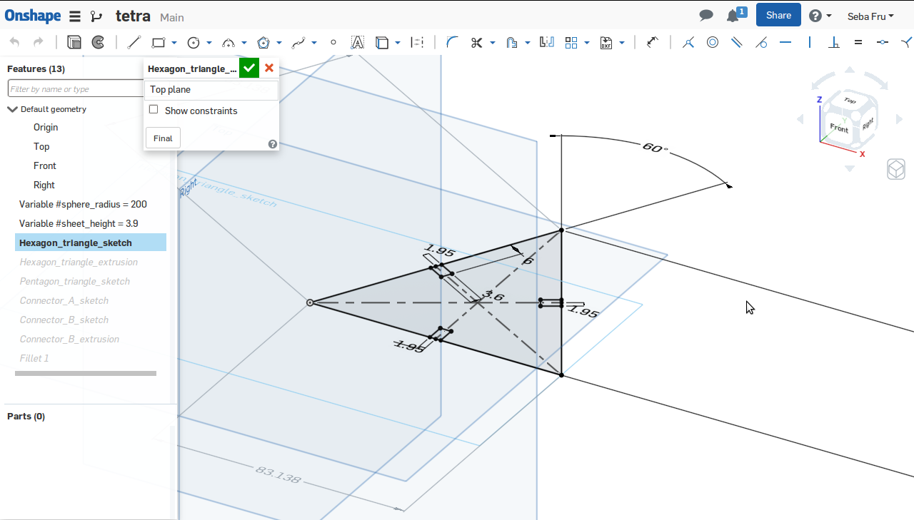
For the tetrahedron parametric model, as requested by the weekly assignment, I decided to use again Onshape 3D software; the term parametric originates from mathematics (parametric equation) and refers to the use of certain parameters or variables that can be edited to manipulate or alter the end result. Although rough usage of variables in a Part Studio (define a name, assign a value) it's quite easy to do -and there are nice tutorials do so, starting from the Onshape Reference- the most difficult thing was to understand how to use variables with regard of the context: while at the beginning I tried to setup a global variable called "#sphere_radius", then I abandoned this approach in favor of using small details variable definition, so it came variable "#sheet_height" referred to the thickness of material to be cutted out
so, after modeling Tetra face, I went ahead modeling Tetra connector
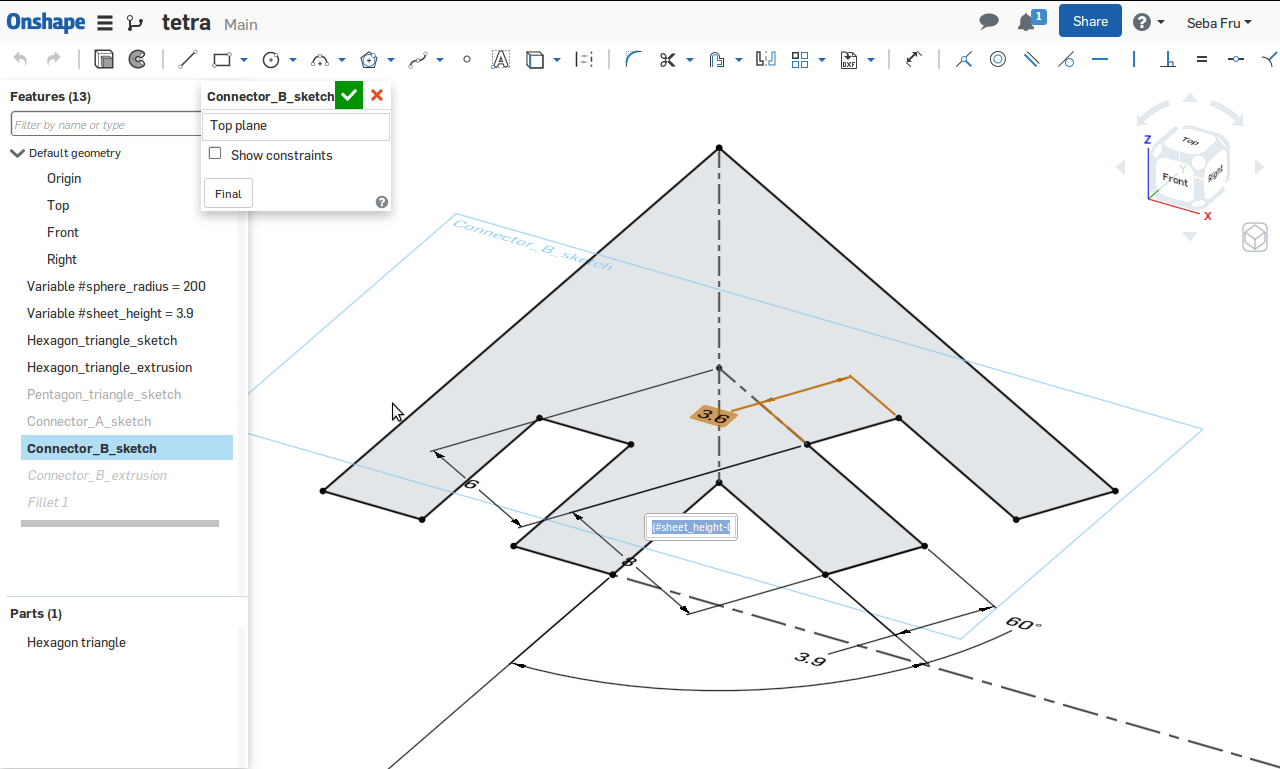
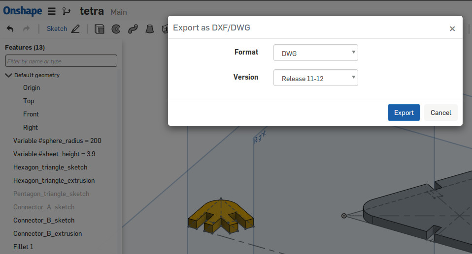
A small note about this two sketches: to obtain some drawing references (e.g. triangle barycenter) I was not only using constraints but also, for the first time, construction geometry: also known as xlines, these are temporary linework entities that can be used as references when creating and positioning other objects (e.g. to create temporary intersections to serve as object snaps). At this point I added some eye-candy fillets and extruded the two objects to complete 3D model; then from it I exported in DWG 2D format the two Top Plane surfaces
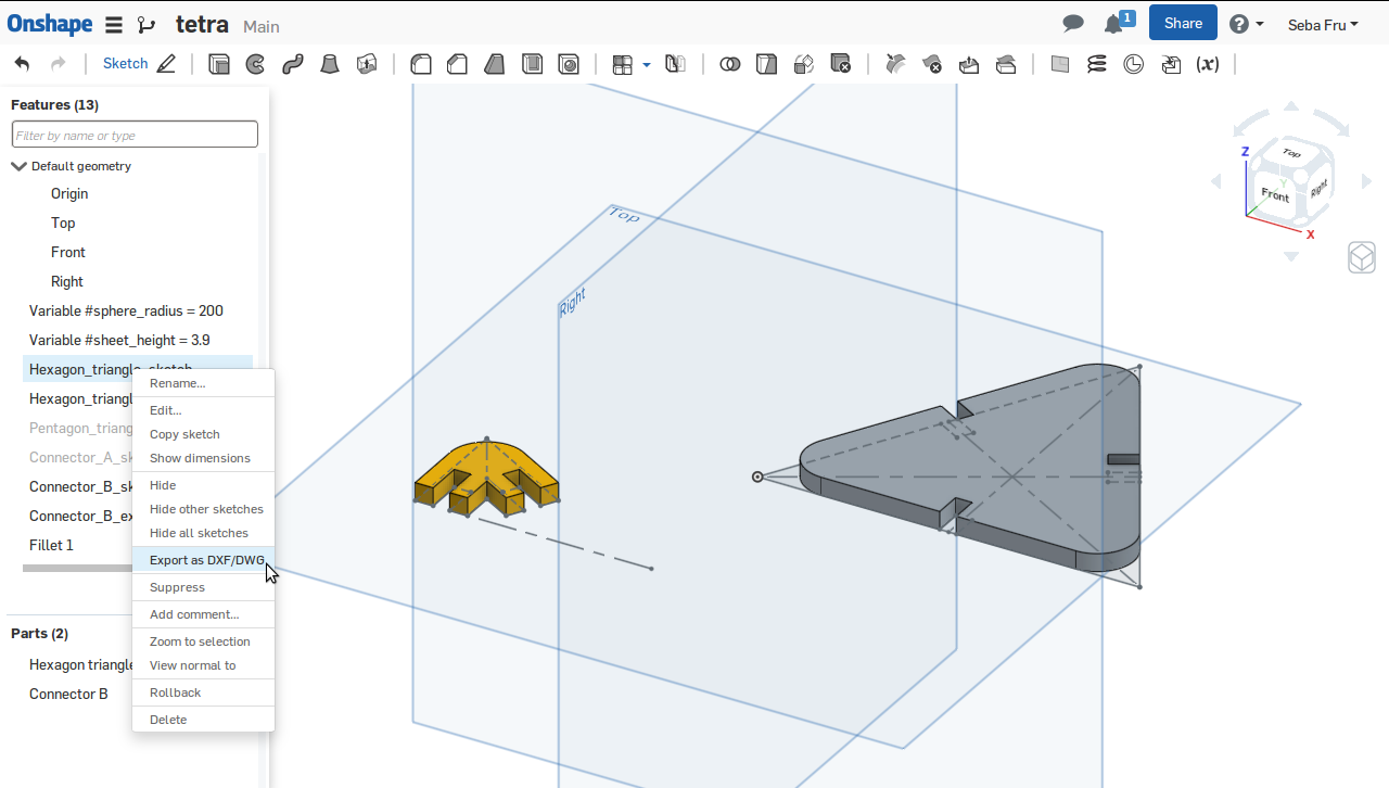
Onshape can export in DXF and DWG formats, and lets you choose the version
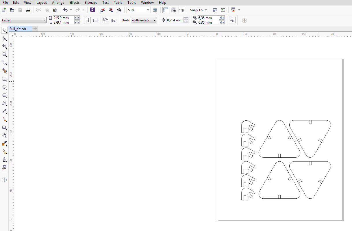
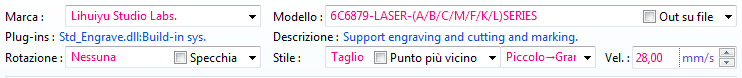
Time to lasercut! I used DWG files as an input for lasercut machine sofware (actually CorelDRAW sofware with the appropriate plugin that came from the lasercutter machine vendor), and at this point I was very unhappy because for the first time since the beginning of Fab Academy class I was forced to use a Windows system proprietary software, and as you may already know (if you read About page or some of the previus assignments pages) as far as I can, I prefer using Free Software. I indeed took a look to the wonderful Fabmodules Project (system independent browser-based CAM software), but it didn't seem to go well together with the lasercut machine controller (Lihuiyu Studio Labs).
From lasercutter machine plugin I set up cutting parameters, like Speed (28mm/s)
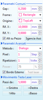
followed by Gap (0,25mm), Frame (Rectangle), Origin (Top Left), Offset (X 10,00mm - Y 0,00mm), Power (75% out of a 40W laser source)
As material I decided to use 4mm thick plywood sheets (again, poplar plywood with a waterbased glue)
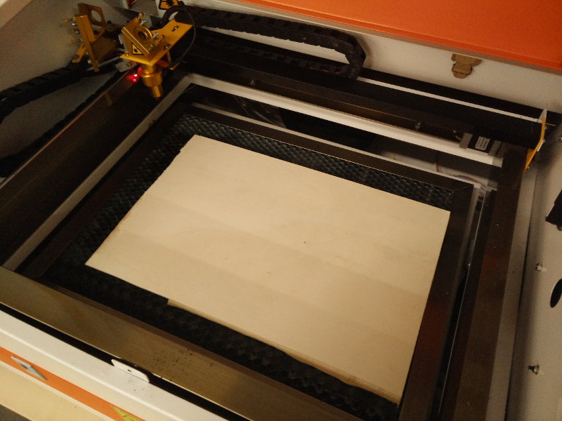
and before starting to lasercut it's fundamental to setup correct laser distance from the material, to keep laser focus in the correct position.
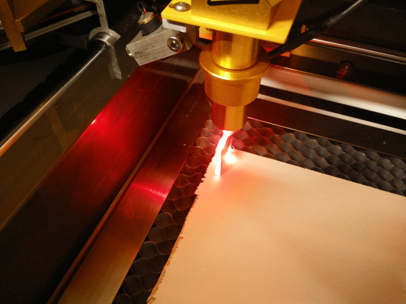
Ready, Set, Go! Lasercut machine performed his job...
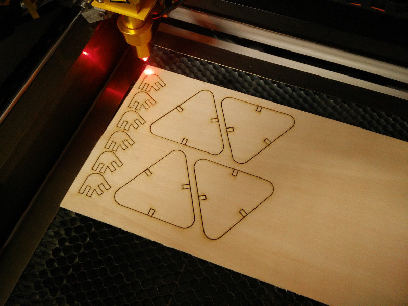
...that turned out to make every single press-fit kit piece...
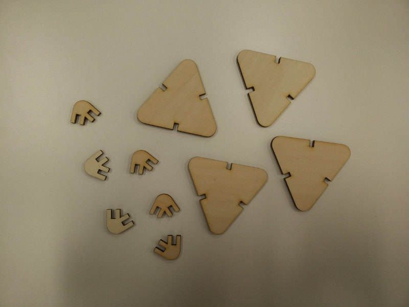
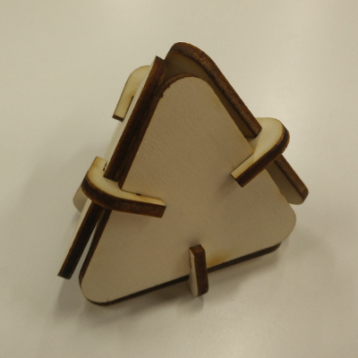
...and here's the "Hero Shot" final assembled result; pieces got together like a charm: not too loose, not too tight; and without a single drop of glue!
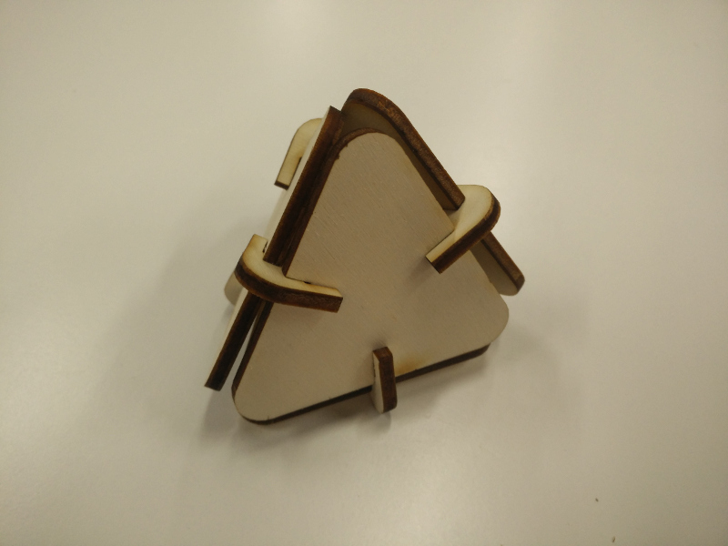
Being a geodesic structure, although reduced to the min, the assembled press-fit kit is very solid.
Source files
- mail.svg -Inkscape output SVG File
- tetra.sldprt -Onshape output SLDPRT File
- tetra.conn.dwg -Onshape output DWG File (Connector)
- tetra.face.dwg -Onshape output DWG File (Face)