Described your design and fabrication process using words/images/screenshots.
Explained the programming process/es you used.
Outlined problems and how you fixed them.
Included original design files and code.
Time is running out and lately all the assignments, need to be linked with the final project in order to arrive to final presentation. My final project organization is the following:
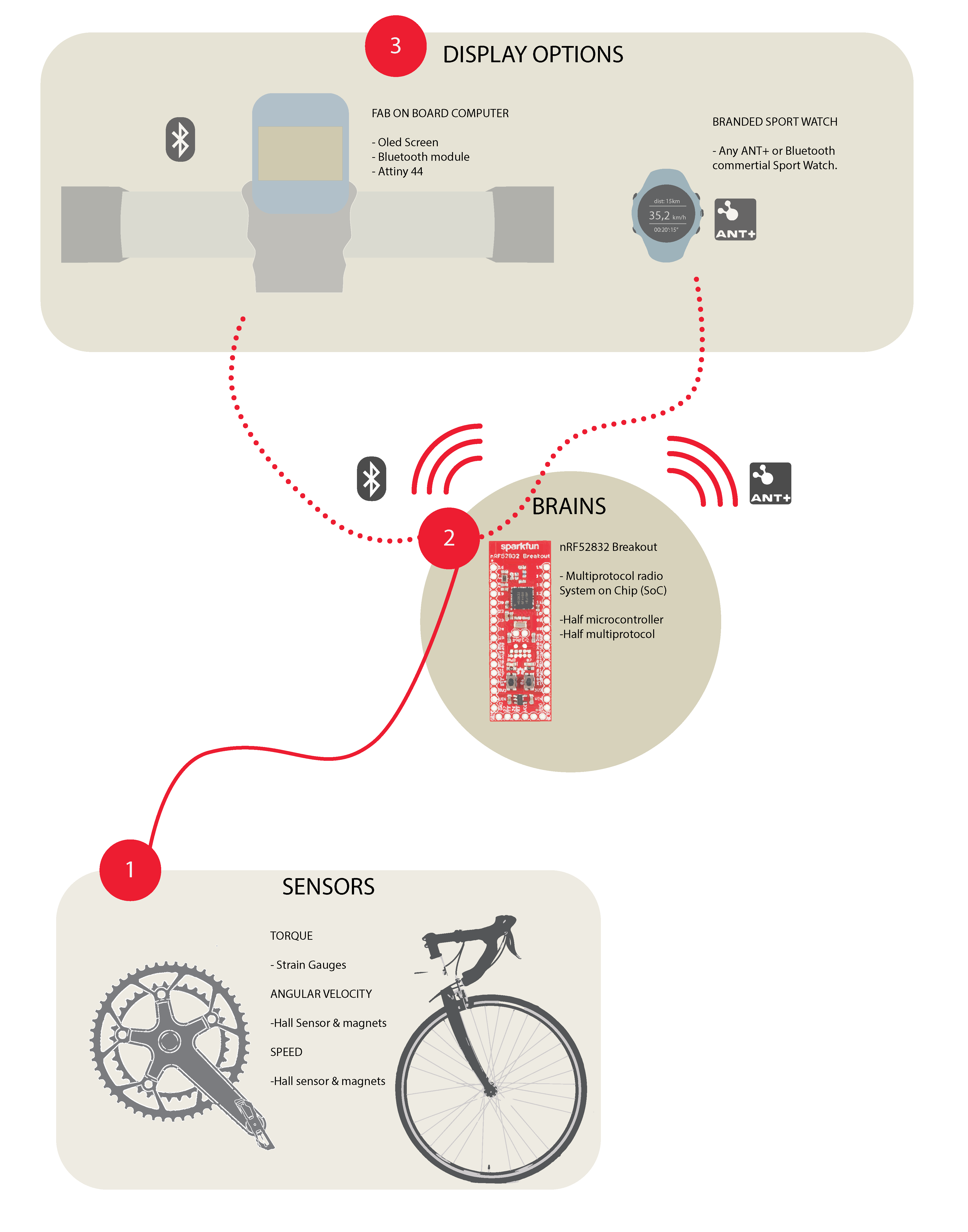
So my own electronics will be developed on the Fab screen that will show the power. It will be a board that with I2C connects to an Oled Screen and by bluetooth will connect to the device brains. In this assignment, we were aimed to design and build a wired &/or wireless network connecting at least two processors. I choose to use Bluetooth as it is a main part of my final project. I made a board that connects to an Oled screen and a hc-sh 08 Bluetooth device, with a ATtiny 85.
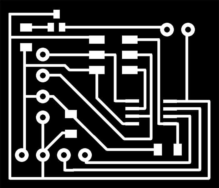
I used an ATtiny 85 because the softwareserial library and an Oled Screen library need more than space than an ATiny 44 could offer and I didn't need so many pins either. Actually the first library I wanted to use fot the Oled Screen was the Adafruit_SSD1306 library, but that with the software serial library was around 12mb. As for Bluetooth, I was going to need the software serial for sure I decided to search for a smaller Oled screen library. Thankfully internet has a bunch of people doing projects with ATtiny 85 and Oled screen, so I run into a bunch of suitable libraries. Without worrying too much about memory space anymore, I jumped to eagle for the pcb design.. I designed the board thinking on having the oled screen on top, the Bluetooth module on the rear part of the board with the battery. Thinking ahead that this screen module would need a case and on packing the electronics the best way possible. This was my first eagle board:
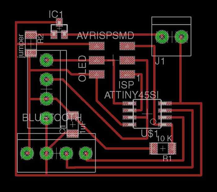
It was the first time I was drilling holes with the Roland SRM-20 and realized that instead of running 2 g-codes paths (one for traces and one for outline) I was going to need a third one for the holes. Before messing up I asked my classmate Sohail and he told me that on the png the holes needed to be black on top of white background to have the diameter I had drawn on the Eagle file. Thanks to him I didn't mess up the whole board!
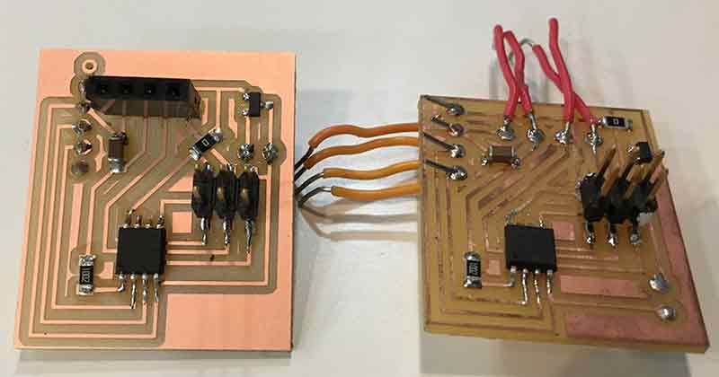
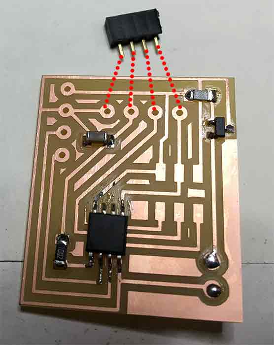
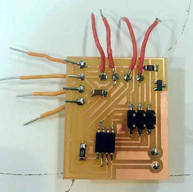
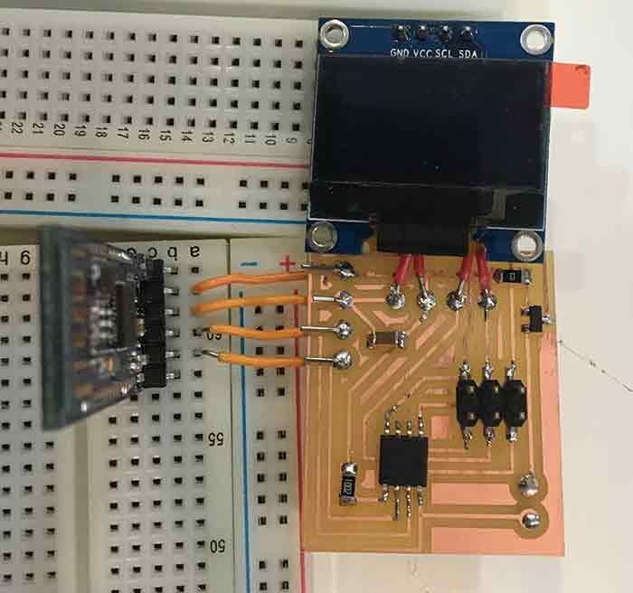
Once I had my board everything seemed all right. I was almost done soldering when I realized these holes were too separated one from each other. I had chosen a wrong component for the header pins and none of the female pins fitted. I was disappointed, but as I had all the other components on place and it was Friday late afternoon I didn't have time to design, mill and solder a new board before weekend. I decided to solder some jumper wires and work through the programming during the weekend. I solved the connection to the oled screen and the Bluetooth module through a breadboard.
Even though I did the programmation of the board with the version with jumper cables, I ended up redoing the eagle with right pin holes and milling it again as it was going to be an esentlial part of my final project.
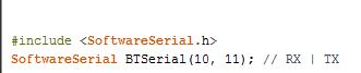
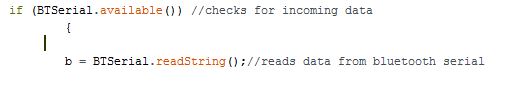
I have been mainly programming with Arduino as I think is the easier to program with no previous experience. This time was not an exception. I had to include a few libraries to get bluetooth communication going on an ATtiny 85. The main one was the SoftwareSerial library. This is a library that allows serial communication for ATtiny chips as they don't have specific RX, TX pins. For using this library apart to include it you have to set which pin will work as RX and which one will do it as TX, as well as give a name to this serial communication. I named my SoftwareSerial as BTSerial. Is important TX,RX are reversed from the ones on the bluetooth module. The good think is even if the eagle is done reversely, you can switch the TX and RX on the code. Once the software Serial library is working you use it as the arduino serial print and read for using the serial monitor. Or as I did, with if (BTSerial.available()) & BTSerial.readString();
To try the bluetooth communication I used LightBlue app. This is an app that allows to send bluetooth strings. The other app that can be used is nRF Connect, both of the are available to used with IOS (As the hc-sh 08 Bluetooth module works with IOS too). Bluetooth modules like the one I am using can work both as master and slaves. Most of the times they come ready to be both. Master is the one in charge of trasmiting data, while slave receives. In this case the master will be the cellphone as it will be the one sending information.
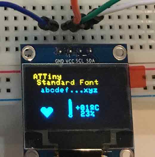
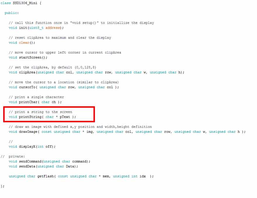
The libraries tend to occupy a lot of space. This is not usually a problem if we use Arduino boards, but when using ATtinies, space gets a little more valuable. For the library size problem, as I had to use Software Serial for sure I had to search for the smalles Oled library I could. I first try with ASCII library for SSD1306, which is only a character display library. For some reason, I didn't get to get it working with the attiny, so I tried the other one I had found. It was through an Instructables that I found SSD1306_minimal library. It was tiny enough for it to fit inside the ATtiny 85 and also complete enough to display bitmaps. I was only going to display text, but having the possibility of adding a logo later on was interesting.
This is the code I used. The Instructables example code that I based my own can be found here.
/*Julia Leirado's Code for sending strings to an Oled Screen Module with an ATtiny85 from a cellphone via bluetooth
comunication
more info http://archive.fabacademy.org/archives/2017/fablabbcn/students/141/week%2015.html*/


#include
SoftwareSerial BTSerial(10, 11); // RX | TX
#include "SSD1306_minimal.h"
#include

#define DEG "\xa7" "C"

#include

SSD1306_Mini oled;

String b;
void splash(){

  oled.startScreen();
  oled.clear();

  delay(5000);

  oled.clear();
  oled.cursorTo(26,1);
  oled.printString( "FAB Power ");

  oled.cursorTo(25,3);
  oled.printString( "Open Source");


  oled.cursorTo(10,5);
  oled.printString( "Bike powermeter");


}


void prepareDisplay(){

  unsigned int i,k;
  unsigned char ch[5];
  String bluetooth;
  oled.clear();
  oled.startScreen();


  oled.cursorTo(0,0);
  oled.printString( "FABpower");
  oled.cursorTo(0,1);
  oled.printString( "BikePowermeter");

}


void setup(){
  BTSerial.begin(9600);
  pinMode(9, OUTPUT);  // this pin will pull the HC-05 pin 34 (key pin) HIGH to switch module to AT mode
  digitalWrite(9, HIGH);

  pinMode(3, INPUT);

  oled.init(0x3c);
  oled.clear();

  delay(1000);

  splash();

  delay(8000);

 prepareDisplay();

}


void loop(){
static long startTime=0;
long currentTime;
const char * databluetooth;
//char buf;
 if (BTSerial.available()) //checks for incoming data
         {
        /* oled.clear();
           oled.cursorTo(0,0);
            oled.printString( "FABpower");
             oled.cursorTo(0,1);
               oled.printString( "BikePowermeter");*/
         b = BTSerial.readString();//reads data from bluetooth serial


        /* int str_len = b.length() + 1;
         b.toCharArray(databluetooth, str_len);*/
       // BTSerial.print(databluetooth);
           databluetooth = b.c_str();


          // printf(buf,"%s\n", databluetooth);
            //printf("%s\n",info);
              // set cursor
             oled.cursorTo(10, 4);

              // print to display
             // oled.printString("test");
             oled.printString( databluetooth );
                               //oled.printString("test2");


 }
}
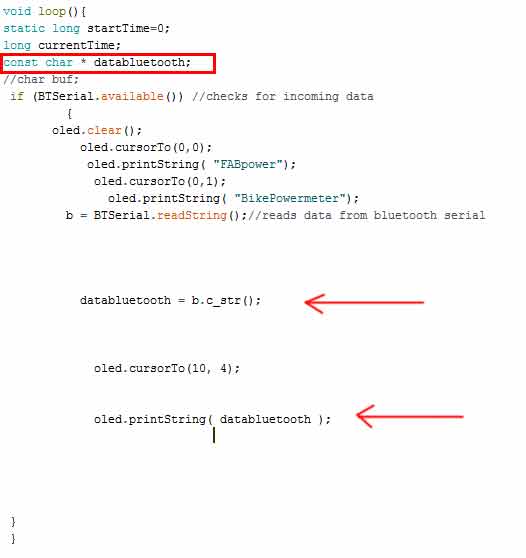
My idea was to send strings from my phone and having them displayed on the screen. I used this tutorial for get started with the hc-sh 08 Bluetooth module. It was made for doing that exact thing with the Arduino and the serial monitor, but it was a great starting point. After having understood it I ungraded it to having the oled display (with the Adafruit library) still with Arduino board. Once that was done it was time for me to jump to the ATtiny board. I was very sure it was going to be very straight forward as I had already my sketch working on the Arduino board. I didn’t realize that using a different library could be a problem. The SSD1316_minimal library was great but it didn't have the function 'SSD1306_Mini::printString(String&)'. Checking the library, I realized I had to transform the string coming from my phone to a Chart.
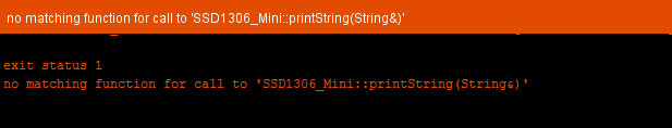
I tried I thousand options before I got it working, mainly because of my lack of programming knowledge. Finally transforming the data coming from the phone to const char, made it possible to work.
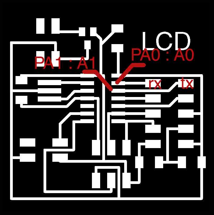
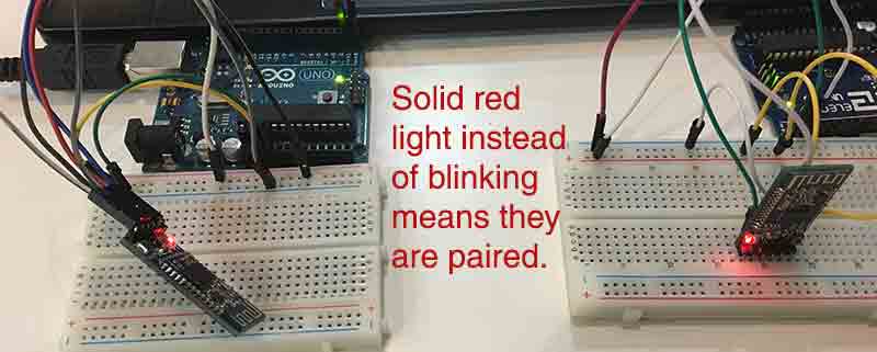
Once I learnt how blueooth works and I managed to have communication between my phone and a microcontroller, I was ready to get communication between 2 microcontrollers. I decided to use the board I did for Input and output. I chose to use this board because is the only one I had with an ATtiny 84, with enough memory to upload an sketch with the softwareserial library. I had enought pins for assigning the rx y tx, as I was not going to use the LCD screen that ocupied most of the pins the first time I used this board. I chose pin 0 and 1 for rx, tx. I had to connect the bluetooth device to the board with jumper cables and powered it with an arduino board. The goal was to use this board to send a string to the ATtiny 85 board and have it displayed on the OLED screen.
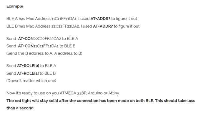
For this to work I had to pair two bluetooth modules. This is something I needed for the final project, so it was a good practise. To pair the Blluetooth modules I checked a lot of webpages, but none of them actual paired the hc-sh 08. Mostly they use sh 05 and 06, the AT commands are a little bit different. Searching the internet, I found that it was almost the same as the SH 10, so I found a on Dan Chen's documentation for Network Communication some usefull information on this last one. I followed it to pair them. The first thing is to get the arduino to enter the AT mode. By default all the bluetooth modules are set on SLAVE mode and to change it we need to enter this AT command mode. Before connecting the hc-sh 08 module ,I uploaded an empty sketch to Arduino. This bypasses the Boot loader of UNO & the Arduino can be used as USB-UART converter. Next I removed the power for arduino and connected the bluetooth device as folllows:
Rx(pin0 ) --> Rx Remember it is one to one connection here & not cross connection
Tx (pin1) --> Tx
+5v --> VCC
GND --> GND
+3.3V --> KEY
Once the connections are properly made I connected back the USB cable power to Arduino. The Bluetooth module entered the Command mode. On the Serial Monitor of Arduino, making sure that "BOTH NL & CR" were selected I was able to use AT commands I got from Dan Chan's documentation to get the adress and the set the proper role for both devices.
The ATtiny 85 board used the same code than when it was communicating with the cellphone. This is the code I used on the ATtiny 84 board, that worked as a master. I programmed it with my fab ISP.
/*
 Julia Leirado's code for
 Network & communication between ATtiny 84 and ATtiny 85 with Oled display
 Code for master board: ATtiny 85 sending a message via bluetooth.

*/
#include
SoftwareSerial BSerial(0, 1); // RX | TX


void setup() {
  BSerial.begin(9600);


}


void loop() {


  BSerial.print("Network");
  BSerial.print("&Communication");  //Up to 3 decimal points


  delay(5000);
}
//=============================================================================================
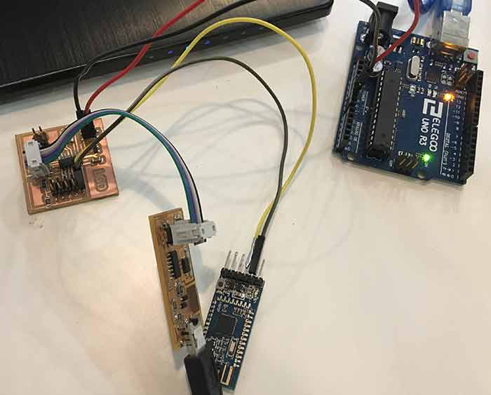
For fully complete the networking asignment, there has to be multiple controllers communicating using addressing. I know that all the boards should be made in the lab, but I had to update this asignment while I was not in the lab and all the boards I could use were the ATtiny 84 pcb I used before (the one I made for output/input week) as a slave and an arduino UNO as a master. I developed the codes and managed the system to work hoping to in the near future be able to change the arduino board for fablab made pcb. I used bluetooth, as I have been growing more confident with it. The pairing between the 2 modules was already done, as I had to do it for the previous networking exercise. The idea was to use one board with a button to ligh on a led on another board. As I had limited ressources I had to improvise. I didn't have a board with a built in led, so I used a breadboard and some jumper cables to connect a LED to one of the pins of my pcb. I wrote this code for this board:
/*Julia Leirado's Code for turn on/off a led with a cellphone via bluetooth
comunication
more info http://archive.fabacademy.org/archives/2017/fablabbcn/students/141/week%2015.html*/


#include
SoftwareSerial BTSerial(0,1);
const int LED = 7; // the pin for the LED
char state;
void setup() {
 BTSerial.begin(9600);
 pinMode(LED, OUTPUT);

}

void loop() {
if(BTSerial.available() > 0){ // Checks whether data is comming from the serial port

state = BTSerial.read(); // Reads the data from the serial port

}

// Controlling the LED

if (state == 'A') {

digitalWrite(LED, HIGH); // LED ON
//delay(10);

}

else {

digitalWrite(LED, LOW); // LED ON


}
//delay(10);
}
I didn't have an ftdi cable to check if the code was working allright. Even it is a very simple code, I have got used to checking them through the software serial monitor. As this was out of the table due to the lack of an ftdi cable I used my cellphone, with the app LightBlue. Sending letters to the ATtiny I managed to turn on/off the led. Anytime I sent 'A' the led turned on, with anyother character the led would turn off, or just stay off.
Once I had check this part of the code I was able to do the code for the arduino, and see the whole system working. Here I used the debounce arduino example as a starter. Instead of turning a led on when the button is high, I send 'A' through serial communication. when the button is low I send 'B'
/*Julia Leirado's Code for turn on/off a led with a button on an Arduino UNO using serial communication (Bluetooth)
comunication
more info http://archive.fabacademy.org/archives/2017/fablabbcn/students/141/week%2015.html*/


const int buttonPin = 2;    // the number of the pushbutton pin

// Variables will change:
char state;
int buttonState;             // the current reading from the input pin
int lastButtonState = LOW;   // the previous reading from the input pin

// the following variables are unsigned long's because the time, measured in miliseconds,
// will quickly become a bigger number than can be stored in an int.
unsigned long lastDebounceTime = 0;  // the last time the output pin was toggled
unsigned long debounceDelay = 50;    // the debounce time; increase if the output flickers

void setup() {
  pinMode(buttonPin, INPUT);
Serial.begin(9600);
}

void loop() {
  // read the state of the switch into a local variable:
  int reading = digitalRead(buttonPin);

  // check to see if you just pressed the button
  // (i.e. the input went from LOW to HIGH),  and you've waited
  // long enough since the last press to ignore any noise:

  // If the switch changed, due to noise or pressing:
  if (reading != lastButtonState) {
    // reset the debouncing timer
    lastDebounceTime = millis();
  }

  if ((millis() - lastDebounceTime) > debounceDelay) {
    // whatever the reading is at, it's been there for longer
    // than the debounce delay, so take it as the actual current state:

    // if the button state has changed:
    if (reading != buttonState) {
      buttonState = reading;

      // only toggle the LED if the new button state is HIGH
      if (buttonState == HIGH) {
        Serial.print("HIGH");
      state='A';
      }
      else{
        state='B';
      }
      Serial.print(state);
      }
    }


  // save the reading.  Next time through the loop,
  // it'll be the lastButtonState:
  lastButtonState = reading;
}
I know that my next step would be to change the Arduino UNO for one of my boards, I hope I will be able to do it in a near future.
HOME