Week5 : 3D Scanning and Printing
3D SCANNING
Prime Sense
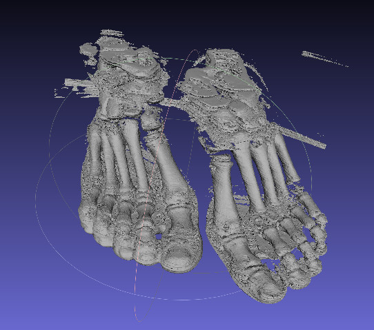
I used prime sense 3D scanner to scan the foot used in my Final project. Ali our Fab Lab co-founder has volunteered to be my subject, but obviously we would need another pair of hands to document the process. The used SKanect software for the scanning process. It is availabe in a free version but the number of polygons is restricted.
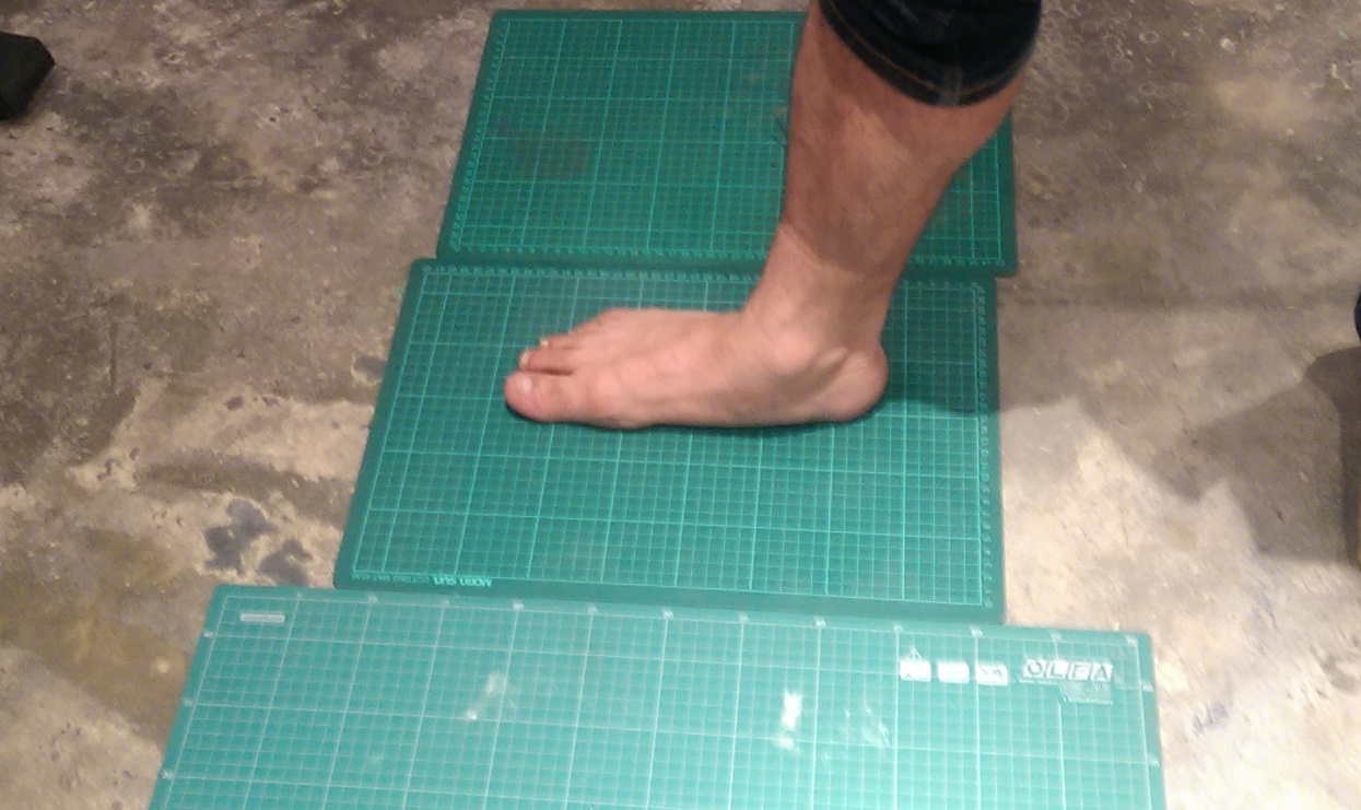
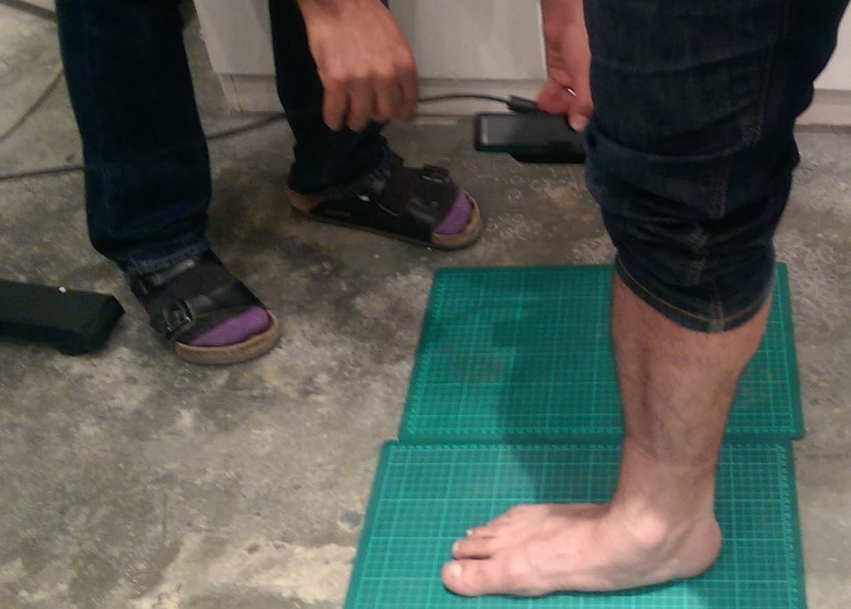
Scanning while rotating around the subject is not an easy task. I guess have a rotating platform would have been ideal.
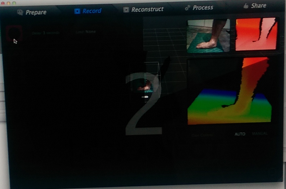
Specially if you decide to limit your bounding box for the scanning. Because the chances that the software can't align the meshes correctly.
But I realized later that most of the details of the foot sole are lost this way
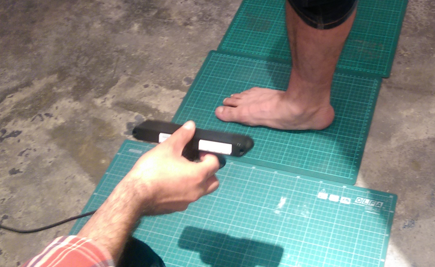
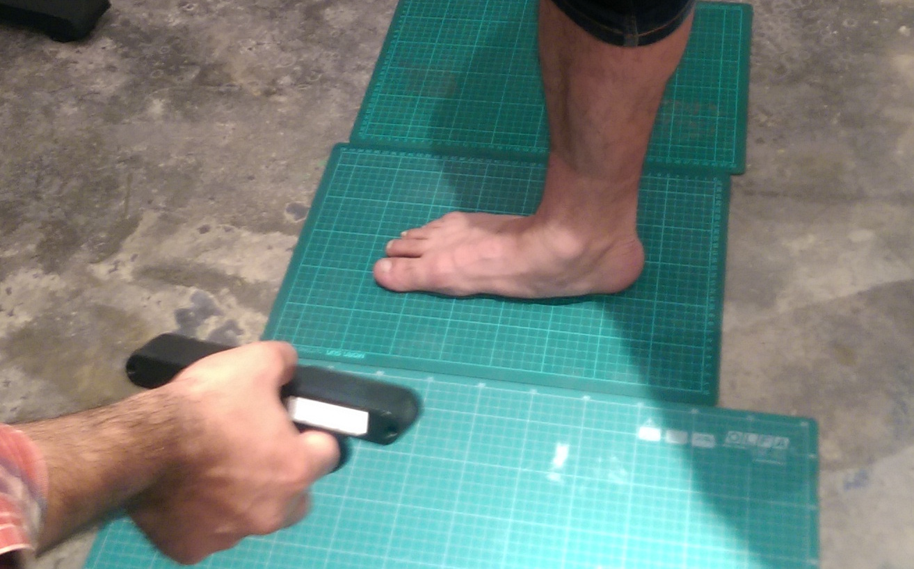
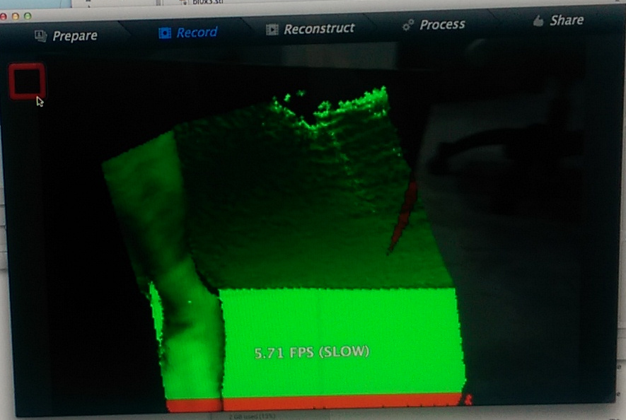
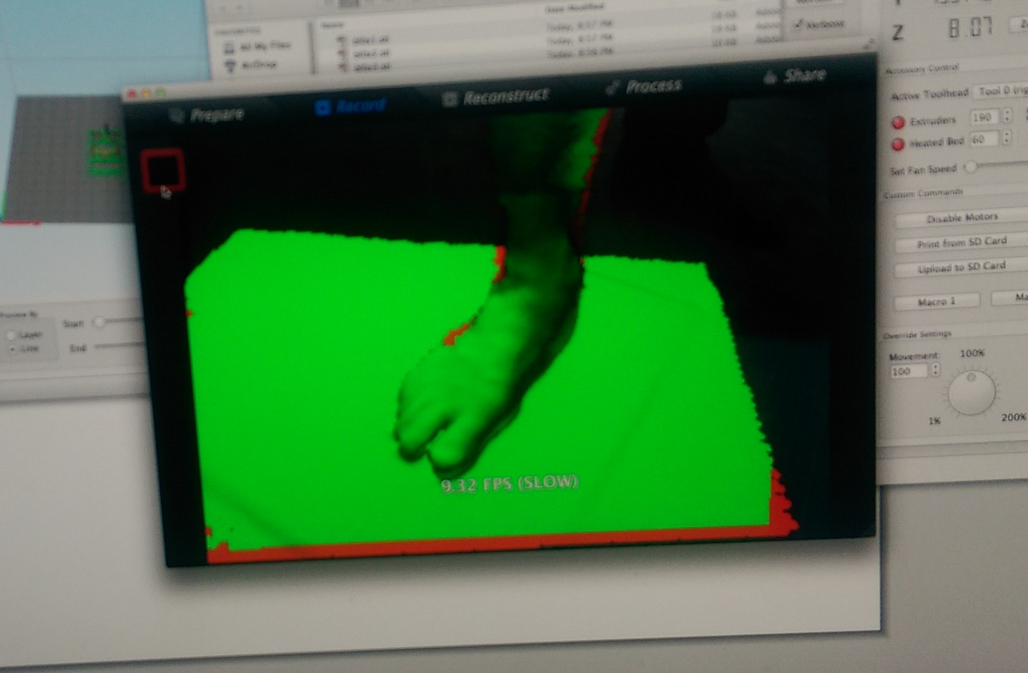
I repeated the scan but this time with the foot susbended.
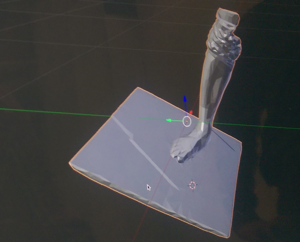
Again some parts of the posterior ankle region where not captured. The initial file was large so I had to reduce the the number of polygons to be able to use it in Blender.
Kinect
I got an old used kinect from a friend and I started with openkinect libfreenect library on ubuntu and was trying out few things. But honestly I just didn't spent enough time developing on that.
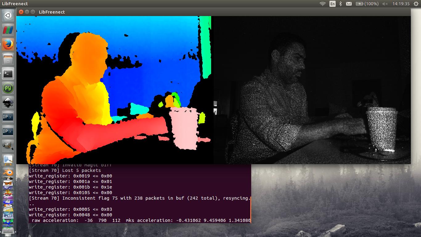
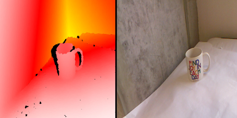
While working with processing I came accross those great resources by Daniel Shiffman. It was easy to test immedatly with it. I found his online tutorials and resources very usefull to learn processing and much more about programming in a very interesting way.
Photogrammetry 3D reconstruction
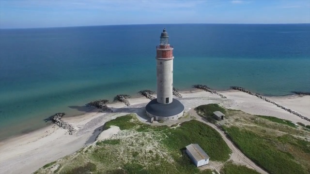
Using some of the many available open source codes for photogrametry I was able to test this technigue on several images and also a drone flyover video.
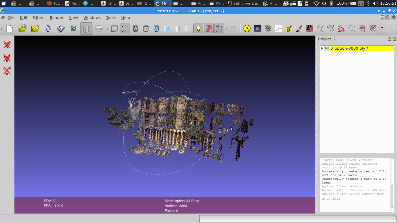
The most stable to use is VisualSFM (Shape From Motion) by Changchang Wu. It also bunddles other key algorithms to produce dense reconstruction.
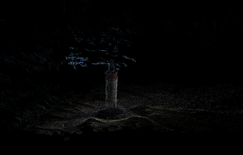
I used this video as a source to reconstruct the following point of cloud
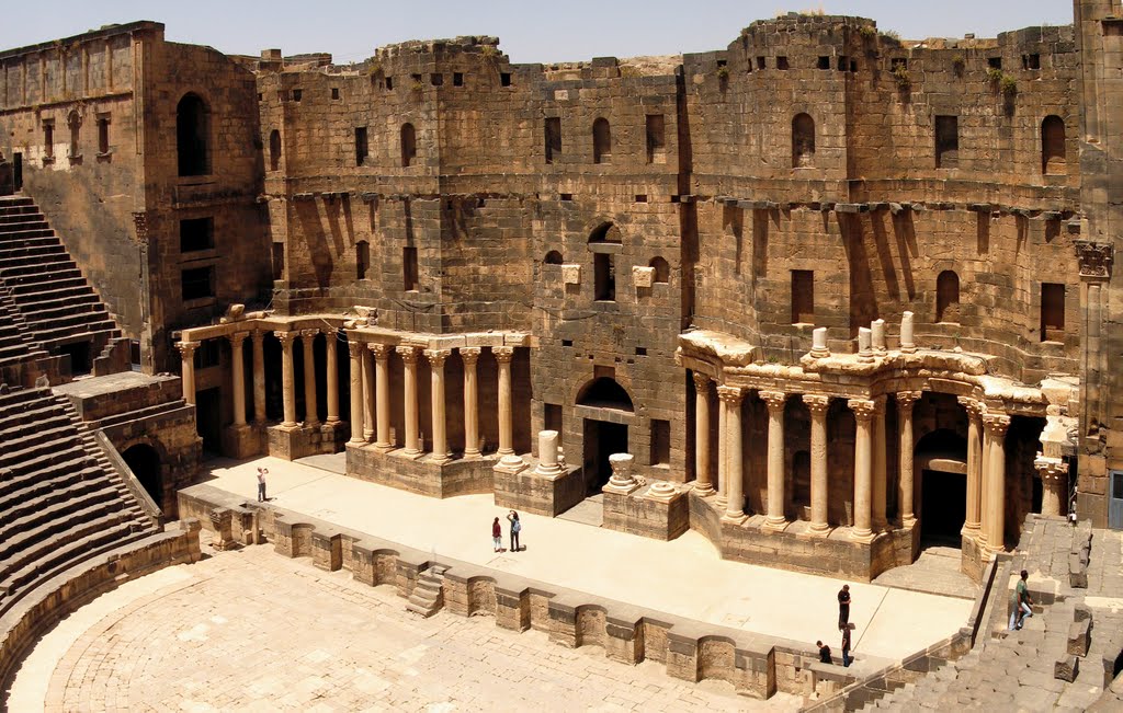
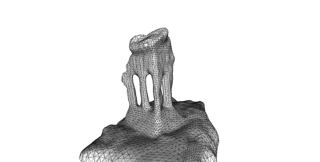
And then using 20 images I found online for a historical theater ruins in Syria in the historical site of BUSRA ( at the time of Testing we were involved in an effort with Arab regional center for world heritage ARCWH to establish a repository of images and a data and attempt to reconstuct some of the site in 3D as a conservation effort).
This also another example using the same method with less number of images
GIF-STL Another Image Reconstruction approach
I wanted to test this fab-modules function and needed to find a suitable GIF file. I searhed for animations

but obviously this was not the best example
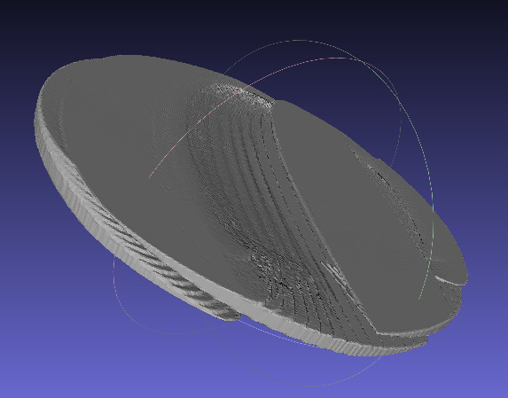
gif_stl sphere.gif sphere.stl
I have used dicom ( a standard file extension for medical imaging files) previously and thought a ct scan data would make a nice gif animation. There are many radiological datasets online, but this time I have used the first link I got in the goolge search.
http://www.osirix-viewer.com/datasets/ Osirix is a open source dicom image processing software for radiological data visualization and processing.
Other more usfeful link is the following https://mri.radiology.uiowa.edu/visible_human_datasets.html
I aim to use the data set to reconstruct a 3D mesh. I wanted to try using the fabmodule gifstl command. obviously the first attempt using the above sphere gif was not the best example. That's why I tried a set of CT scaned images.
Using a simple python script I read the dicom images converting the saved jpeg to a gif animation, since there is no module or a straight forward way to do so in python I used a much easier command line conversion method using ImageMagick library.
convert -delay 100 -loop 0 image*.jpg animation.gif
Then using the fabmodules also through comand line I got the stl file
and using a simple threshold segmentation in python I get the bone only
The following are python codes to convert a DICOM file (.dcm) to a jpeg images. The second one also does a simple threshold segementation of the image to keep pixel values with intensity close to bone. To use the code the source of .dcm files has to be changes ( it's a local folder) and the destination folder to save the images too.
3D design for printing
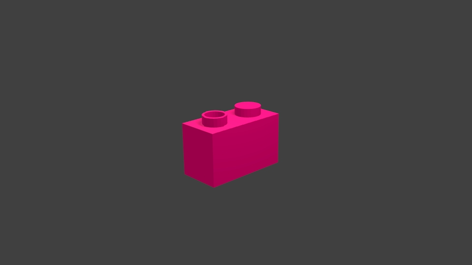
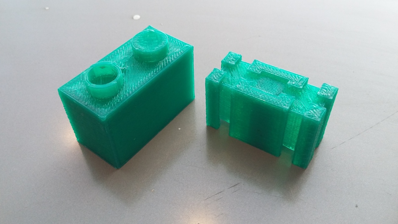
For the intitial project BLOX ( Toy Blocks that can identify each other and map the order of their assembly to visual interface tree). I used FELIX3.0 printer. I used the designes done on Sketchup and exported them as .obj files and then using blender I exported the mesh again as .stl.
I rendered a squence in blender of the final results for fitting the different parts together
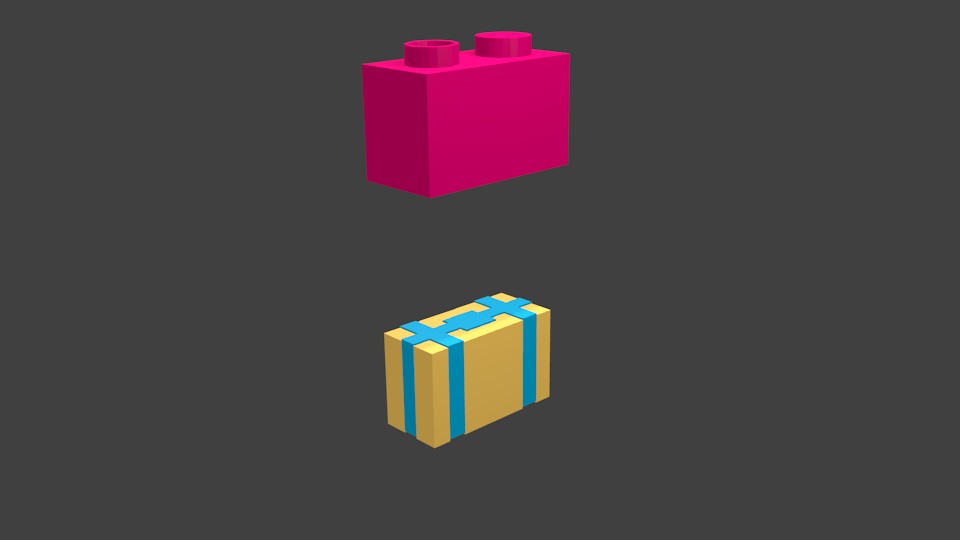
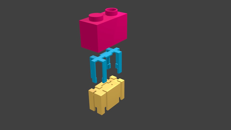
I printed the 3 parts together with a 20% infill.
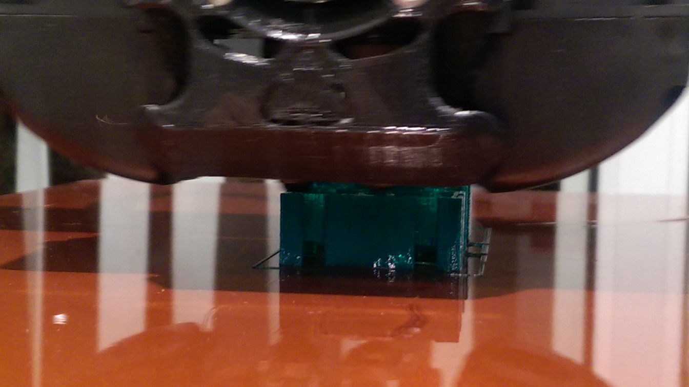
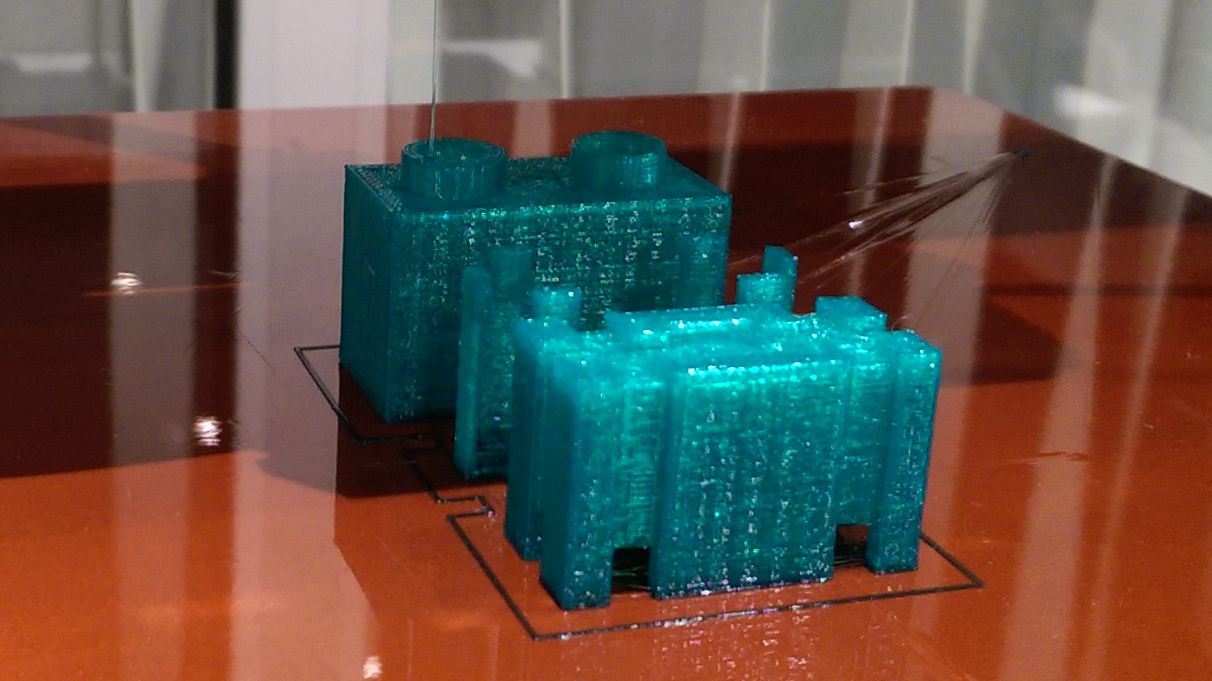
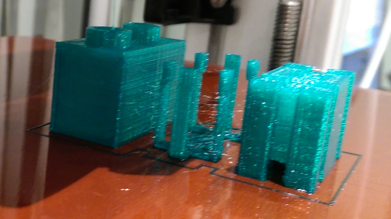
one of the things I didn't account for while designing the block is the shrinkage factor after 3D-printing. I used PLA which has a shrink factor of 2-3%, which is enough to not have parts fitting correctly specially if they should snug in closely. In the case of ABS that number is increases to 8%. In my case this made it impossible to fit the parts together.
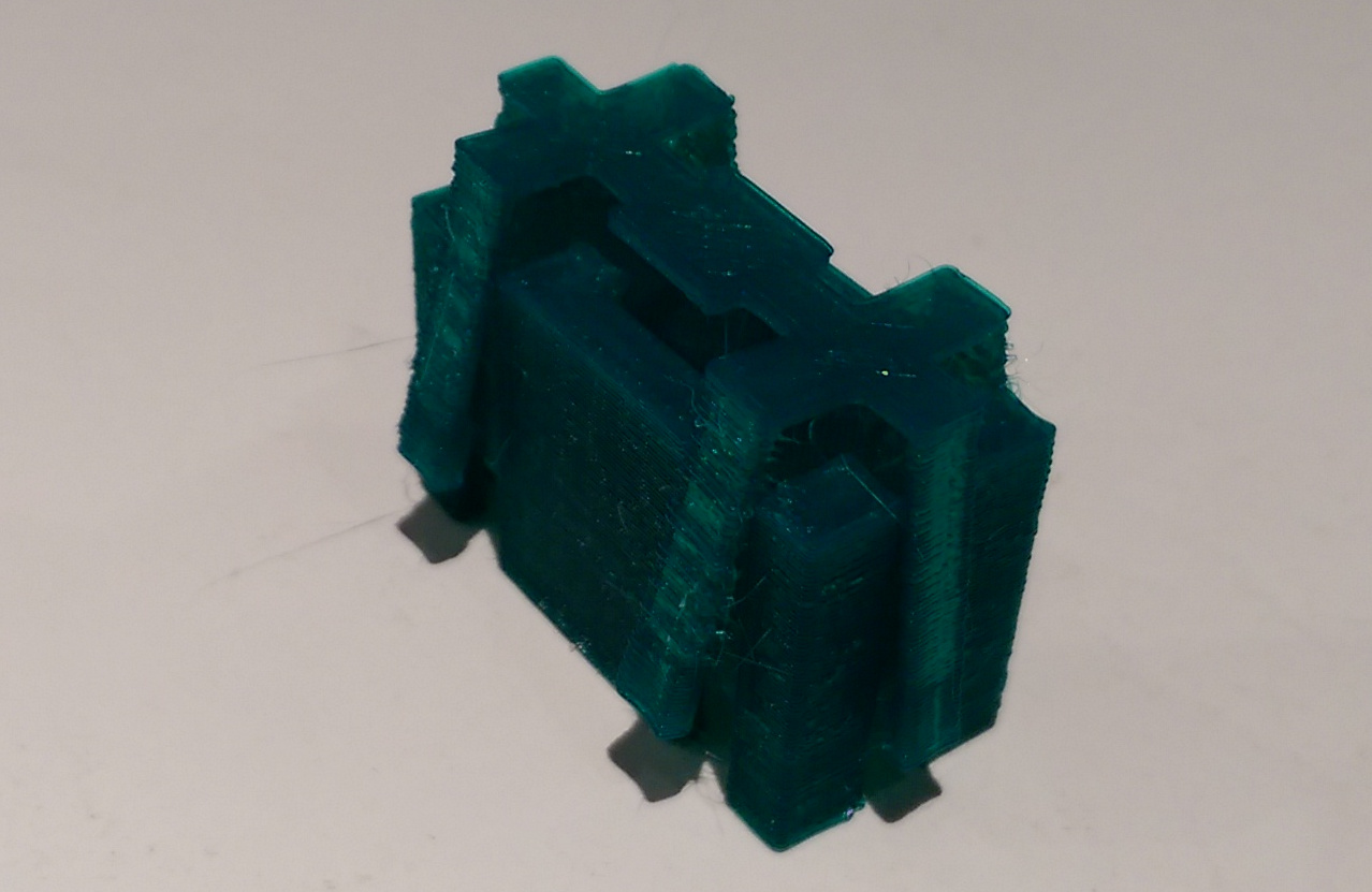
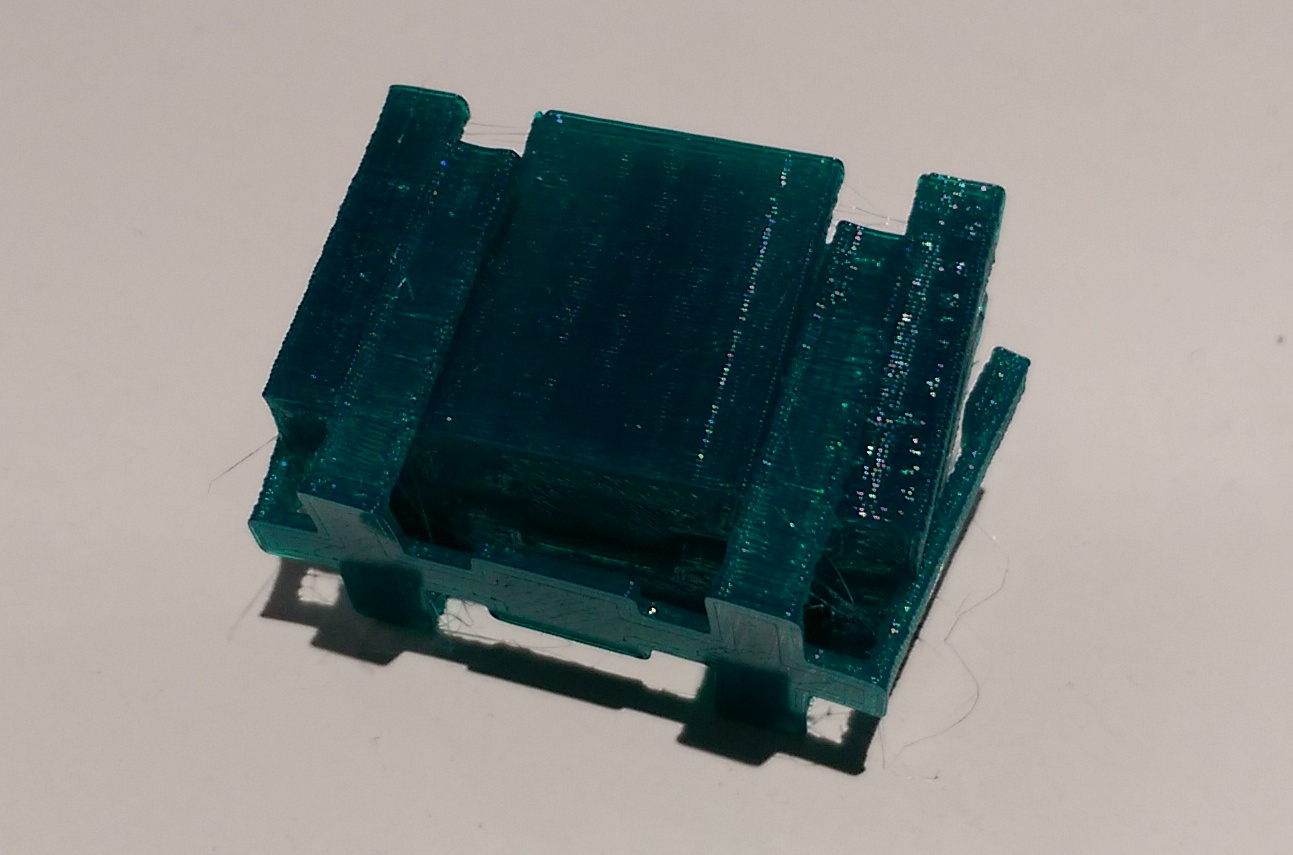
except for one area where the studs fit in the socket.
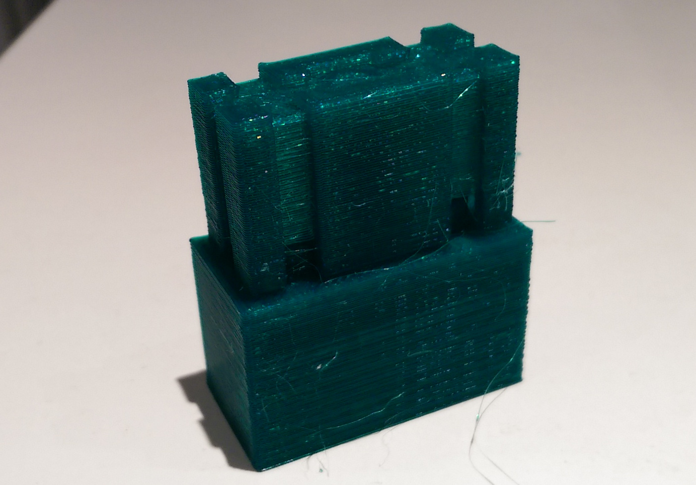
and not also in the way the have to fit as one final piece.
I have to account for that in the future prints.
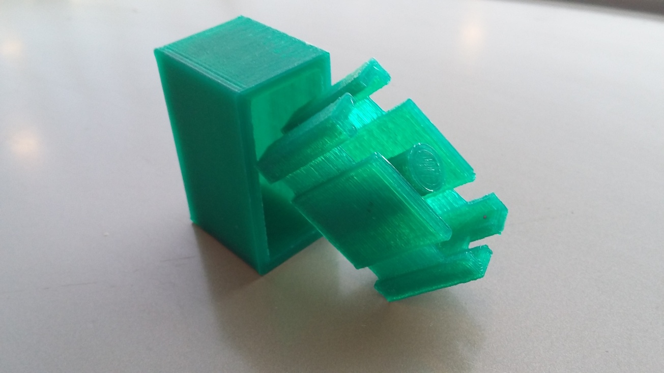
I did test to print other stuff, for example this is a key chain design for the fablab I did sometime back..
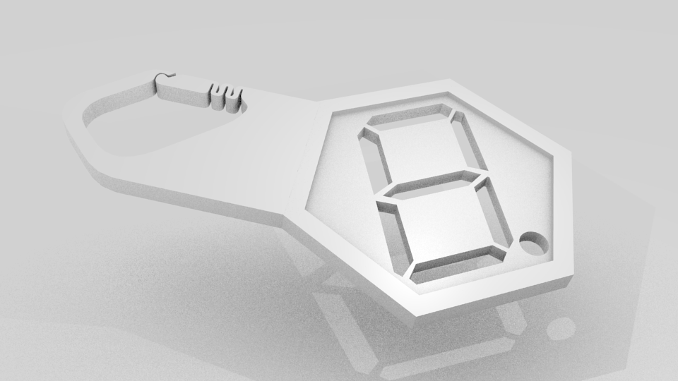
I tried printing several sizes, but the hinge kept breaking, so I thought I would keep it simple and use a chain ring with it.
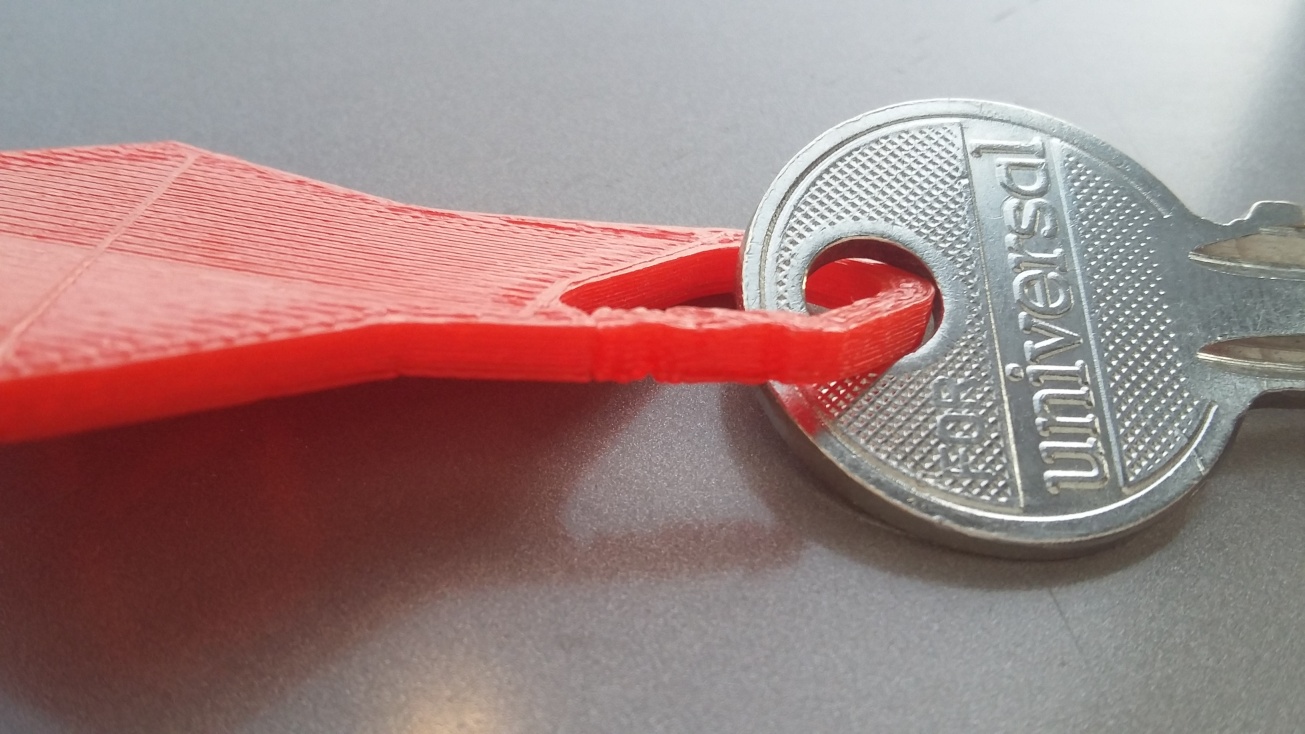
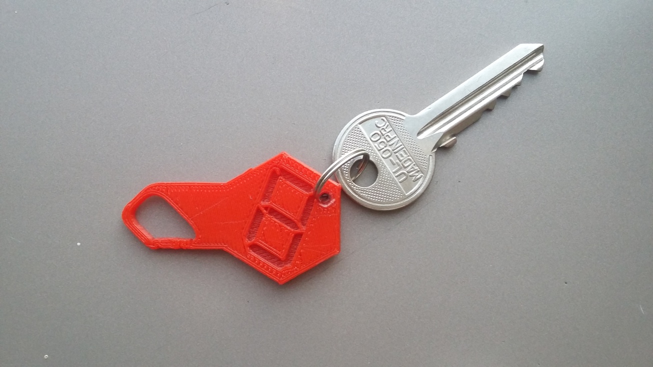
Obviuosly the design of the hinge can be improved, the parametric openscad code I did in WEEK 3 for 2D with some improvements I can do it on a third axes by simple extrussion.