WEEK 15 - Networking and communications
TASK:
Design and build a wired &/or wireless network connecting at least two processors
Objectives:
- Design & build 3 boards for Serial Asynchronous
- Program and test board for communications
Design & build 3 boards for Serial Asynchronous
Eagle files: Keith_bridge45.brd
Keith_bridge45.sch
Keith_Node1_45.brd
Keith_Node1_45.sch
The main objective this week is to create network communications between processors.
Amongst the various platforms Neil introduced during the class, Serial Asynchronous
was chosen due to it's simplicity. The main idea is to send data to a bridge board (master)
which then sends to the node boards (slave). The result of the reponses can be seen from
the blinking LED lights on every board with every input typed in from the computer keyboard.
Below is the list of components used for the bridge (1x) and node boards (2x) with an ATtiny 45 chips:
Bridge Board
- ATtiny45
- Capacitor 1uf
- Resistor 1k
- Resistor 10k
- LED
- 2x2 pin header- For chain connections
- 2x3 pin header- For connections with programmer
- FTDI
Node Boards (2x)
- ATtiny45
- Capacitor 1uf
- Resistor 1k
- Resistor 10k
- LED
- 2x2 pin header- For chain connections
- 2x3 pin header- For connections with programmer
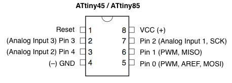
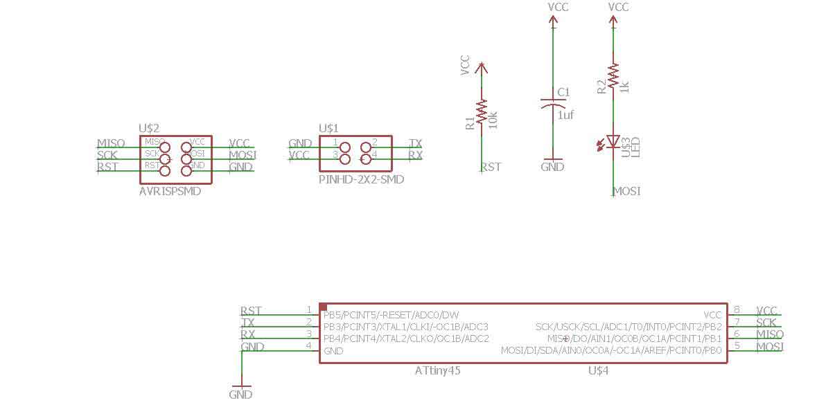
ATtiny 45 connections reference
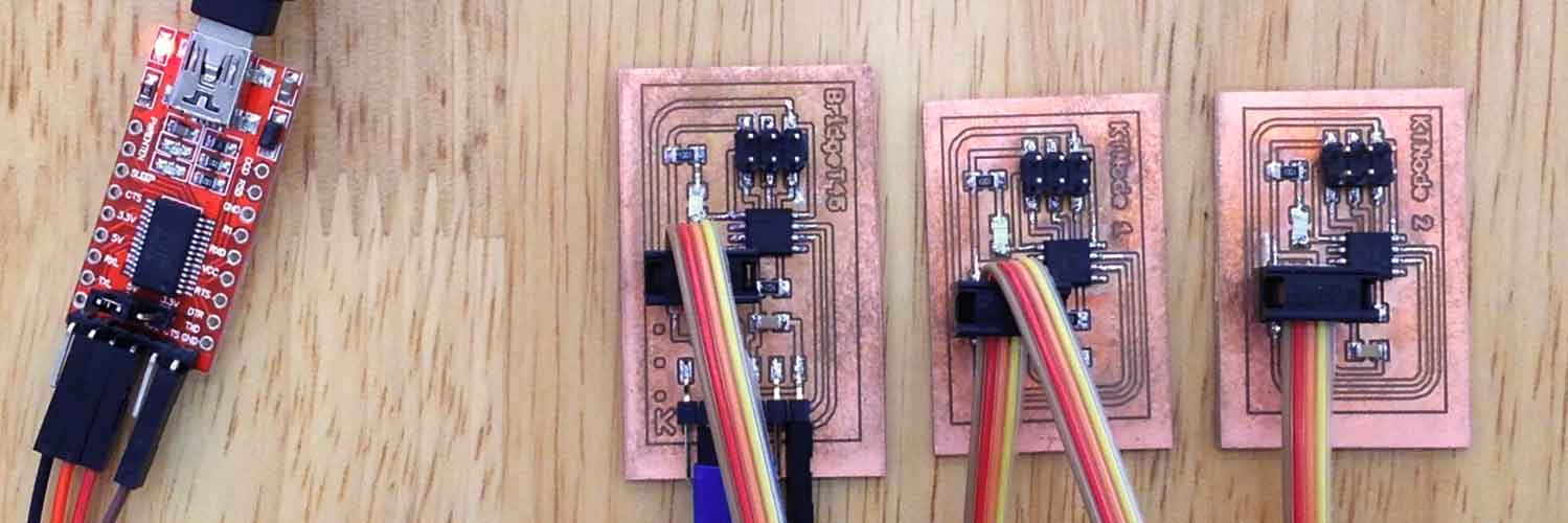
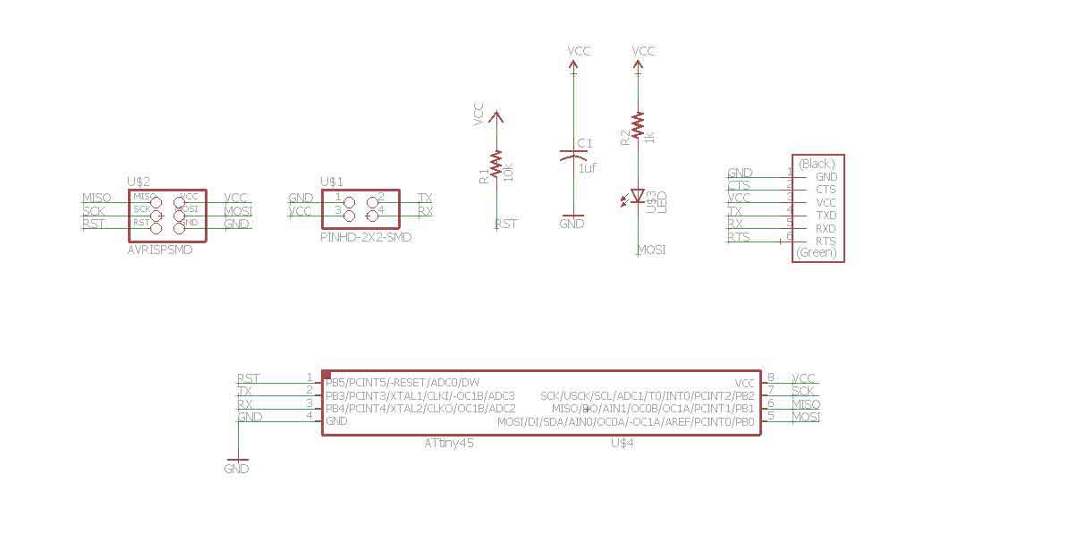
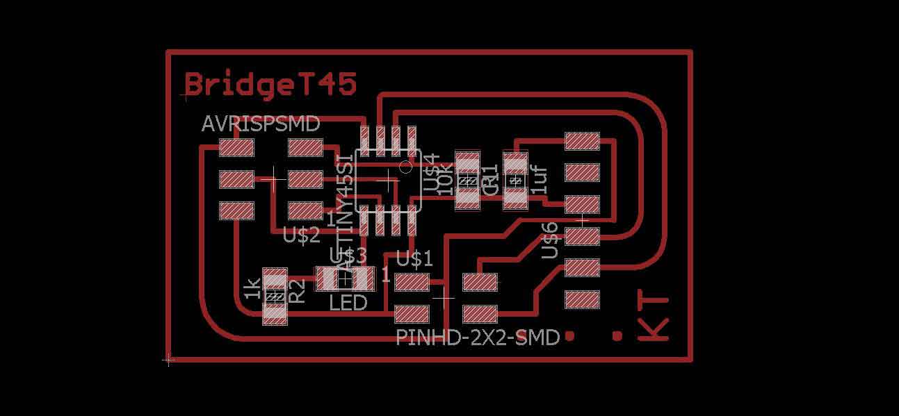
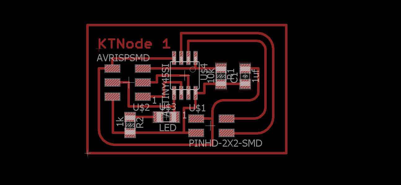
The following are images of schematics and board designs laid out for the assignment. As there were quite a number of references from the previous Fab Academy students' and also due to the fact that by now we have been exposed to the interface for several sessions already, setting up the designs was quite easy.
Some of the main differences from the previous boards that have been made in the previous assignments were that the LED was connected to MOSI and that the bridge board is the only board that has FTDI connector. Node 1 and 2 boards are completely identical.
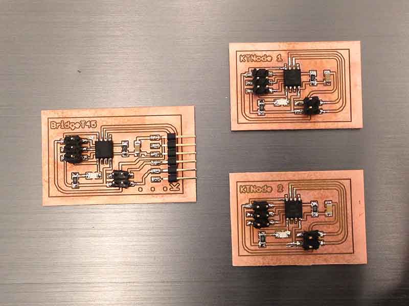
Surprisingly, milling and staffing the boards was quite enjoyable. Familiarity with the dos and don'ts really helped to minimise errors and quicken the pace dramatically. Having said that, the LED was soldered with the wrong direction. The positive side, denoted by a green dot on the LED, should be facing towards the ATtiny 45.
Program and test board for communications
Arduino ISP: ArduinoISP.ino C-code: hello.bus.45.c Hex-code: hello.bus.45.c.hex Make file: makefile hello.bus.45.make Output file: hello.bus.45.out
Map of process:
- Prepare Python environment
- Upload Arduino ISP to Arduino for programming (refer to Week 8)
- Connect arduino to bridge board via ftdi connector
- Flash chip using c file and makefile
- Repeat from step 3 again for Node boards 1 & 2
- Connect all 3 boards via USB to FTDI board using IDC cable (refer to Week 4)
- Run term.py program via command prompt
- Test responses of boards via computer keyboard
1) Prepare Python environment (Windows platform)
Install:
- Python 2.7
- Pip for Windows
- Pyserial
- FTDI drivers for Windows
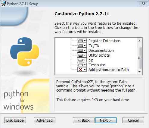
Install Python 2.7
Ensure that the Add python.exe to Path is checked during the installation process. Failure to do so will hinder execution of python commands as it is unable to locate system files.
Install Pip
First, download the get-pip.py file from the link stated above. Go to the website and right-click to save the file. Once downloaded, execute command prompt and go to the directory where the py file was saved. Next, type in python get-pip.py and press Enter.

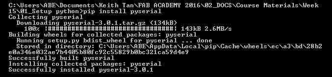
Install Pyserial
Pyserial was installed via the command prompt environment. Type in pip install pyserial and press enter.
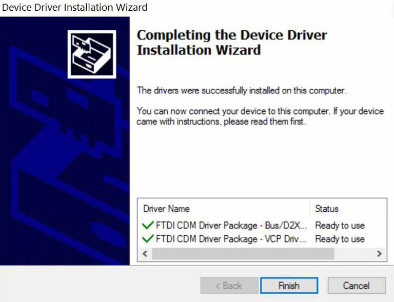
Install USB to FTDI Driver
Installing the FTDI driver is simple but waiting time can be quite long. So long as you see the Installation Wizard window shown below, you're set to move on. Click "Finish"! Ensure that driver is installed properly by checking the Ports under Device Manager.
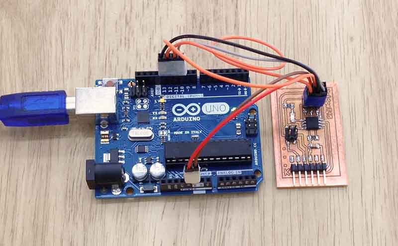
2) Upload Arduino ISP to Arduino for programming (refer to Week 8)
3) Connect arduino to bridge board (or node 1 or 2 board) via ftdi connector
4) Flash chip using c file and makefile
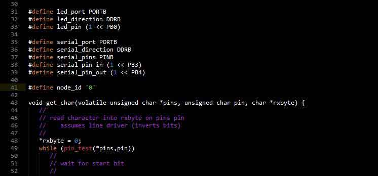
To program the ATtiny 45, ensure that the c file, provided in the class repository, has been amended to function for the respective boards. For the bridge board, the node id '0' (line 41 shown in image below) should not be amended. For the node boards, the first one should be amended to node id '1' and the second board node id '2'. The files can be saved as seperate files but for this exercise, the files were overwritten so as to avoid having too many files. All other codes should remain as default.
Once the c file is saved after amending the id, execute the following commands. Remember to go into the file directory first:
cp hello.bus.45.make makefile [press enter]
make [press enter]

[System generated message]
avr-gcc -mmcu=attiny45 -Wall -Os -DF_CPU=8000000 -I./ -o hello.bus.45.out hello.
bus.45.c
avr-objcopy -O ihex hello.bus.45.out hello.bus.45.c.hex;\
        avr-size --mcu=attiny45 --format=avr hello.bus.45.out
AVR Memory Usage
----------------
Device: attiny45

Program:     704 bytes (17.2% Full)
(.text + .data + .bootloader)

Data:          4 bytes (1.6% Full)
(.data + .bss + .noinit)
Next, program ATtiny 45 using avrdude:
avrdude -P com6 -c stk500v1 -b 19200 -p t45 -U flash:w:hello.bus.45.c.hex [press enter]

[System generated message]
avrdude: please define PAGEL and BS2 signals in the configuration file for part
ATtiny45
avrdude: AVR device initialized and ready to accept instructions

Reading | ################################################## | 100% 0.07s

avrdude: Device signature = 0x1e9206
avrdude: NOTE: FLASH memory has been specified, an erase cycle will be performed

         To disable this feature, specify the -D option.
avrdude: erasing chip
avrdude: please define PAGEL and BS2 signals in the configuration file for part
ATtiny45
avrdude: reading input file "hello.bus.45.c.hex"
avrdude: input file hello.bus.45.c.hex auto detected as Intel Hex
avrdude: writing flash (704 bytes):

Writing | ################################################## | 100% 1.17s

avrdude: 704 bytes of flash written
avrdude: verifying flash memory against hello.bus.45.c.hex:
avrdude: load data flash data from input file hello.bus.45.c.hex:
avrdude: input file hello.bus.45.c.hex auto detected as Intel Hex
avrdude: input file hello.bus.45.c.hex contains 704 bytes
avrdude: reading on-chip flash data:

Reading | ################################################## | 100% 0.85s

avrdude: verifying ...
avrdude: 704 bytes of flash verified

avrdude: safemode: Fuses OK

avrdude done.  Thank you.
5) Repeat from step 3 again for Node boards 1 & 2
6) Connect all 3 boards via USB to FTDI board using IDC cable (refer to Week 4)
The IDC cable should be connected to the 2x2 pin headers on every boards. Ensure that all connections are connected via the same wire (observe the colour of wire). It took quite a while to realise errors generated during programming was due to connection error. The IDC cable was connected with only 4 wires instead of 6.
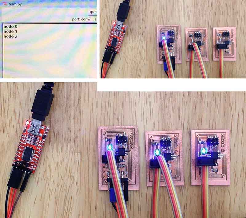
7) Run term.py program via command prompt
First, in command prompt, ensure that you are in the directory where the term.py was saved. Next, enter the following commands:
python term.py com6 9600 [press enter]7) Test responses of boards via computer keyboard
Once the term.py interface appears, simply type in "0" or "1" or "2" and the boards will light up in the pre-assigned blinking patterns.
Reflections
It's been a very humbling week! All-in-all, the assignment was actually quite straight forward if not for the following errors made during the programming process:
- Amended more than just the node id in the c file. Mistaken MOSI with MISO where MOSI was connected with LED. Because of this, led_pin (1 << PB0) in c file was changed to 2 instead of 1.
- During first attempt of testing the responses with term.py, it was set with 19200 bud rate thinking that it should be similar with the bud rae of the chips. All chips should be programmed with 19200 and term.py should be in 9600.
- Bad solder didn't help. During programming, some parts (fdti connector and ATtiny 45) of the boards had
to be removed and resoldered. Error messages looked like this:
avrdude: please define PAGEL and BS2 signals in the configuration file for part
ATtiny45
avrdude: AVR device initialized and ready to accept instructions

Reading | ################################################## | 100% 0.07s

avrdude: Device signature = 0x000000
avrdude: Yikes!  Invalid device signature.
         Double check connections and try again, or use -F to override
         this check.


avrdude done.  Thank you.

Related Projects