Week Eight
This weeks assignments
- Read the datasheet for the ATtiny 44
- Try as many programming methods as possible
- Program the controller to do something
- Uploading program to the ATtiny
Reading the datasheet
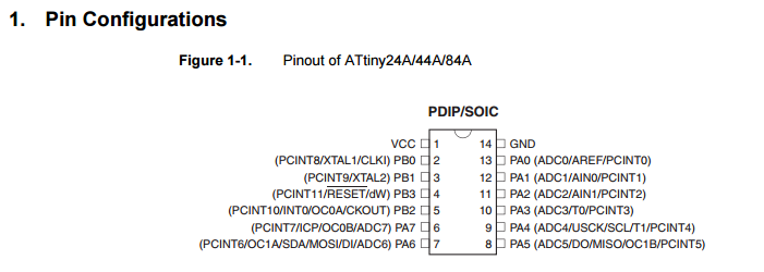
The most notable part that I learned from the datasheet was about the MISO, MOSI and clock, aswell as the pin configuration ofcourse.
I would like to learn much more about the controller, but I feel like I need to work with it quite a bit more to begin to grasp its fullest potential.
Try as many programming languages as possible
The arduino IDE
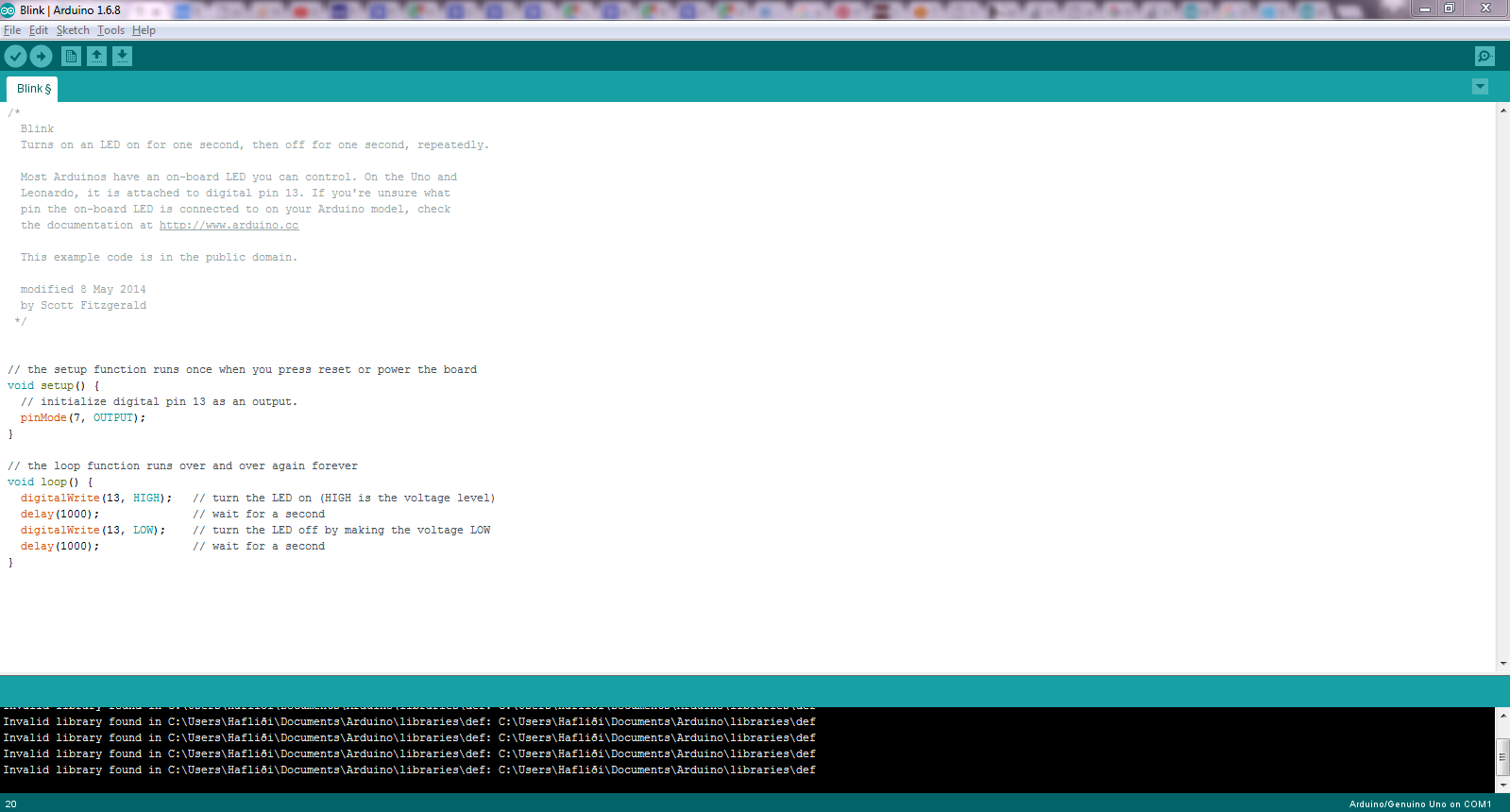
In order to be able to use the IDE the latest version of the IDE needed to be downloaded. After that the ISP needed to be registered within the IDE as a method of programming the ATtiny. I followed this tutorial to be able to upload a program through the IDE. Just to test the LED, I first uploaded the basic arduino BLINK to the PCB. With the datasheet I could see which pin was relevant to the LED.
Directly using C.
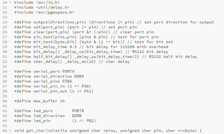
Using brackets, C can be written directly and uploaded to the microcontroller with a the make file supplied by the academy. A simple program - with the structure gotten from the academy aswell, was modified to blink the LED diode on the PCB if a digital input was aquired.
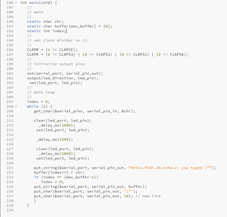
Programming the controller to do something
By pushing the button the led flashes three times.
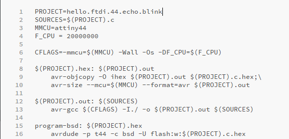
Uploading the program to the ATtiny.
With the C program file and the make file gotten from the Academy, it was possible to upload the program to the microcontroller. First of, the make file was modified such that it referenced the new C file - called hello.echo.blink.
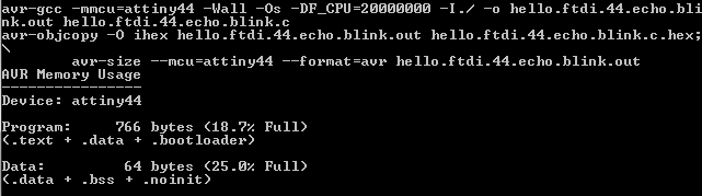
So, by opening up command prompt in the folder where the make file is we call on to the program with "make -f..." and the make file:

And we get prompted with this message if everything went well:
Next we write "make -f... call the make program... program-usbtiny-fuses":

Prompting us with this message:
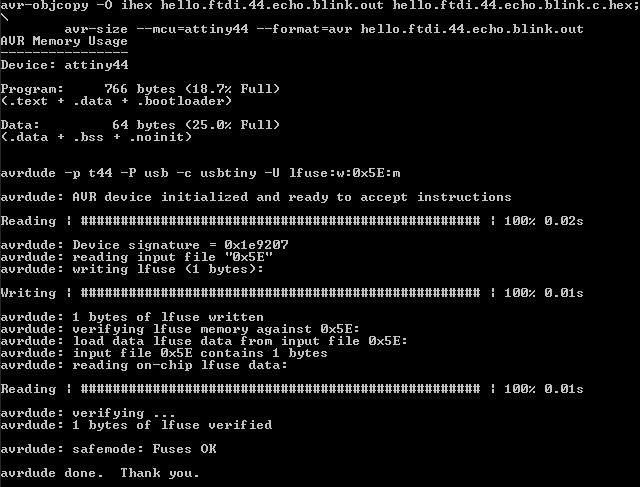
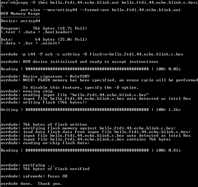
And then again we write "make -f... make file again... program-usbtiny":

And we get prompted with this message that tells us everything went well.