Week Five
This weeks assignments
- Test 3D printer parimeters
- 3D print something
- 3D scan something (possibly print out aswell)
3D print something/testing parimeters
Input UPDATE 7.7.2016. Shapeshifter seems to be down and my original file is missing. On the bottom of the pages is an explanation on another project that I did for my final project.
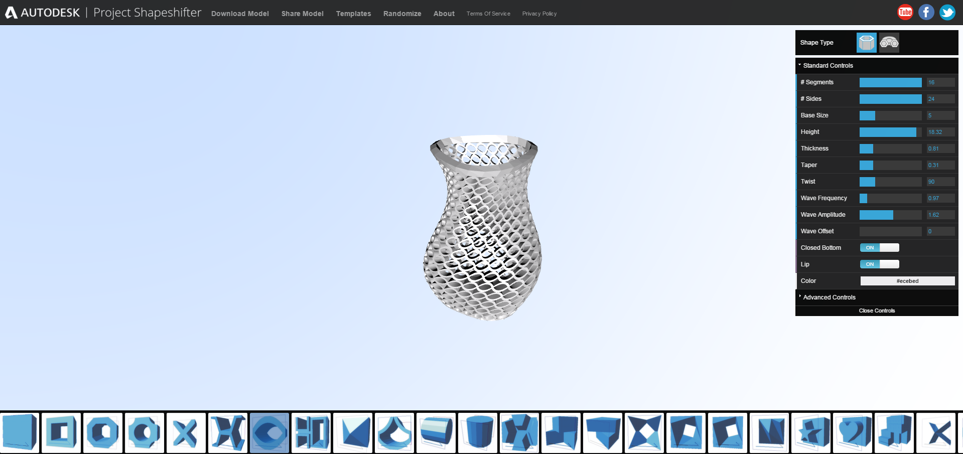
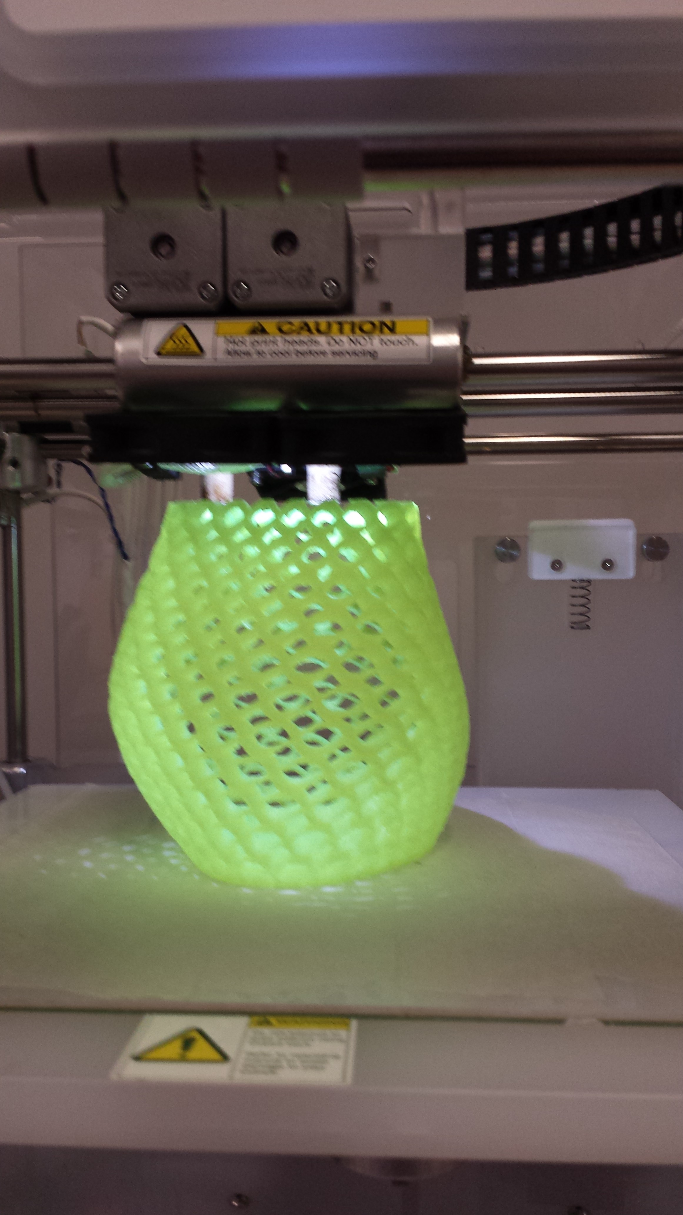
I've already 3D printed a bunch of models so testing parimeters and just printing something felt a bit mundane and repetitive. I looked around at other student pages and found Shapeshifter, an autodesk browser product. Its awesome in its simplicity. I wanted to test my printers capacity to print larger objects that take longer time. A very porous vase was cosen to be the labs next showpiece. Final picks first.

The vase was designed using Shapeshifter. I wanted something that was tall and not very wide and aesthetic, and obviously not something that could be made using anything but 3D printing. I changed a bunch of the original design parimeters, but made sure that I wasn't unpractical to print or the fanal product be ugly.
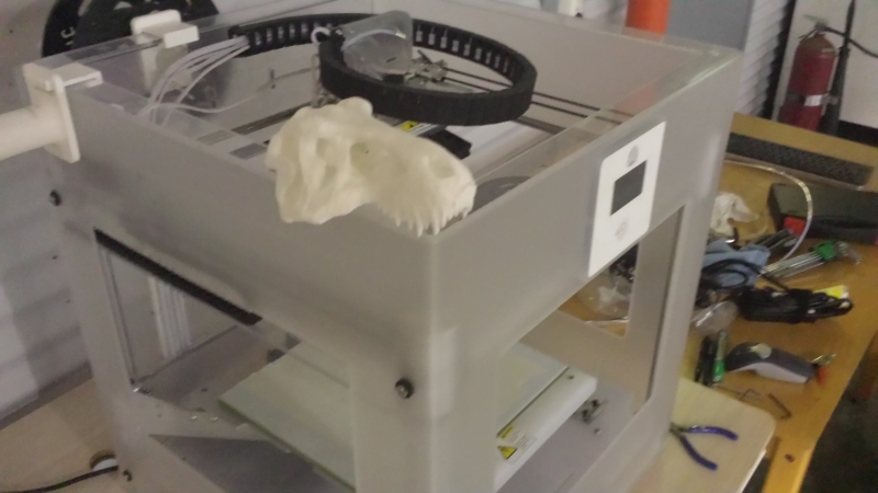
The vase was downloaded as an STL file. Now, our printer is a CubeX duo and, as described by the vendor, capable of printing up to 28x28x28cm. The vase downloaded was 19cm. Here we can see it with its dinosaur skull shoulderpads.
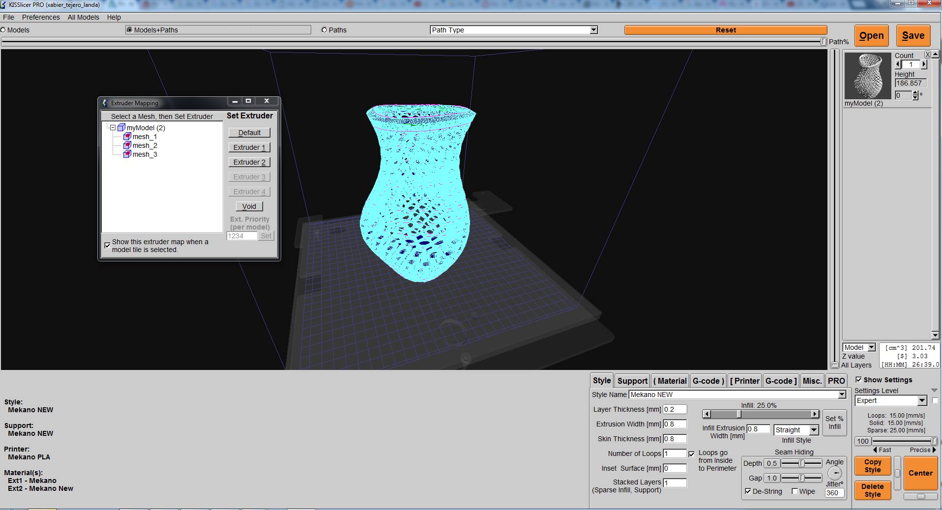
The printers software is no good so we found a software called KISSLICER. KISSLICER is absolutelly awesome. I'm not sure if it can operate on any other printers, but the individual that designed the software is very gifted, it's really easy to use but has a lot of features. First impression with the program. Here we can see what pops up when the STL is first loaded into the program. It even shows the printing plate relative to the model.
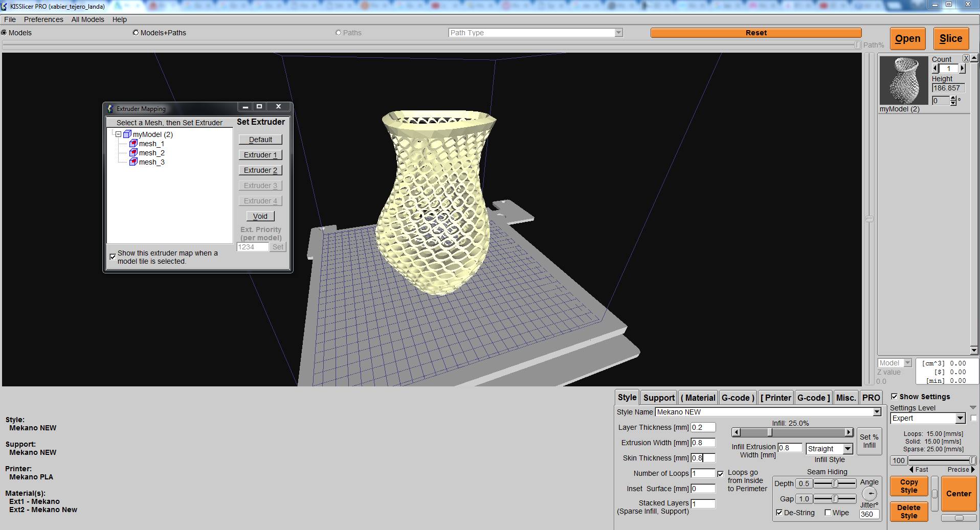
The model can be adjusted slightly, scaled, roteted, other models added to be printed at the same time or the same model printed several times. Now, to adjust the printing precision, supports etc.
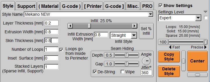
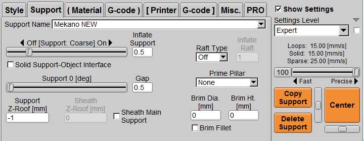
Our printer allows for up to 0.2mm layer thickness (the z-axis) and down to 0.8mm extrusion width. The nozzles are exchangeable but we've been fine with these thicknesses. Additionally the infill can be adjusted manually, from 0% to 100% and everything in between. We've done quite a few experiments in the past and never really found any infill problems. The program also allows for different supports to the models, whether it be different models of rafts under the model to get a better grip to the printing plate, pillars or the like. Now, after the model is sliced, this is the how the model looks (the sliceing is even quite graphic and displays every layer individually if requested). I was afraid that I might corrupt the slicing if I took a screenshot...
Now, the g-code is saved to a USB thumbdrive to transport to the printer. The printed does not allow to be fed directly from a computer. We use painters tape for the plastic to stick to the printing plate when using PLA. We dont have a heated plate for ABS, but we've been looking into DIY's. Lets start printing.
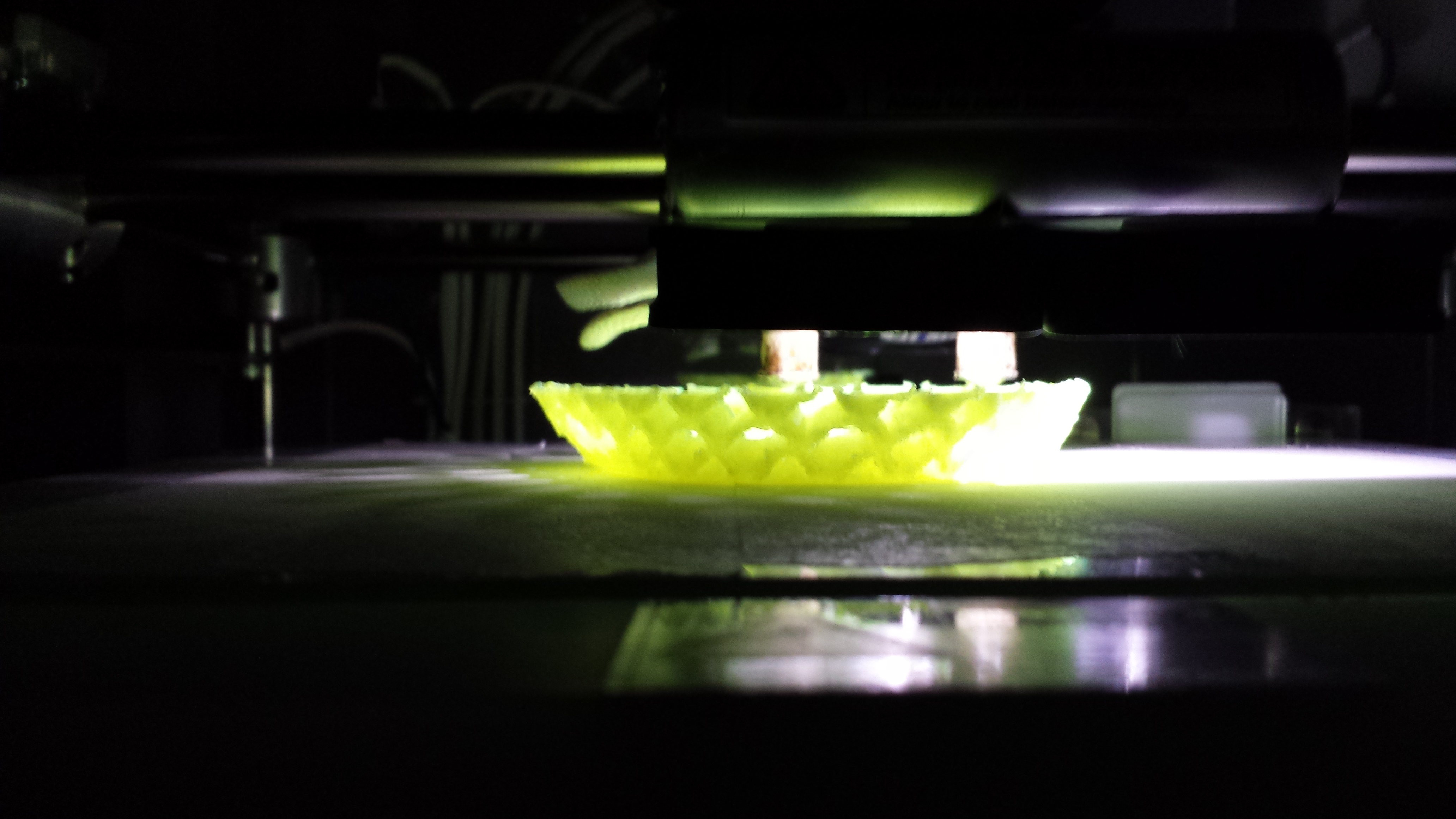
After roughly an hour I had the base... Long print awaits.
And about 36 hours later, the print was finished... coolio. Many people commented on that it might be a terrible flower vase since it might not hold any water. I say, infidels.
Now, lets look at some of the print quality.
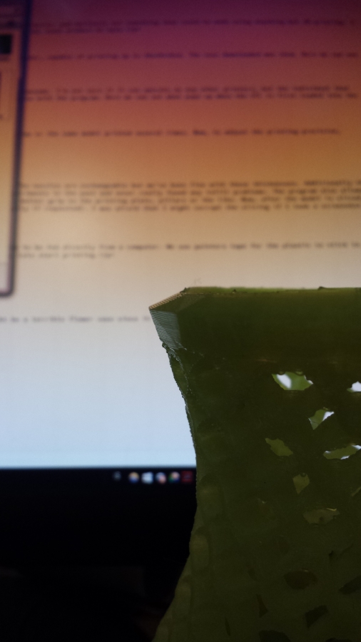
Now, this is a big model, so the quality might not be as "in your face" good/bad, but the edges are very sharp and the faces very smooth. All in all, I'm very happy with it.
Update 7.7.2016 continued.
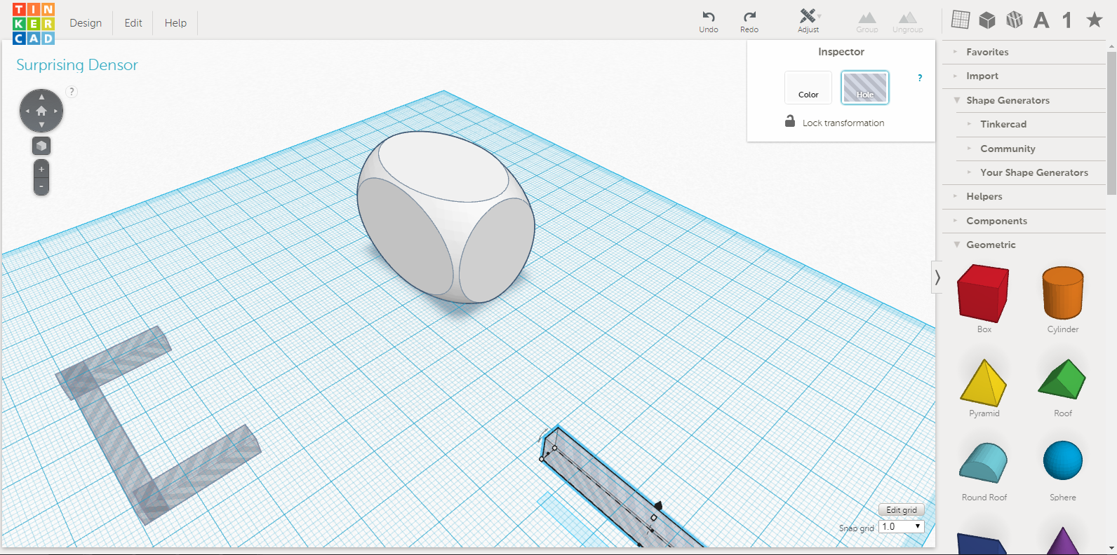
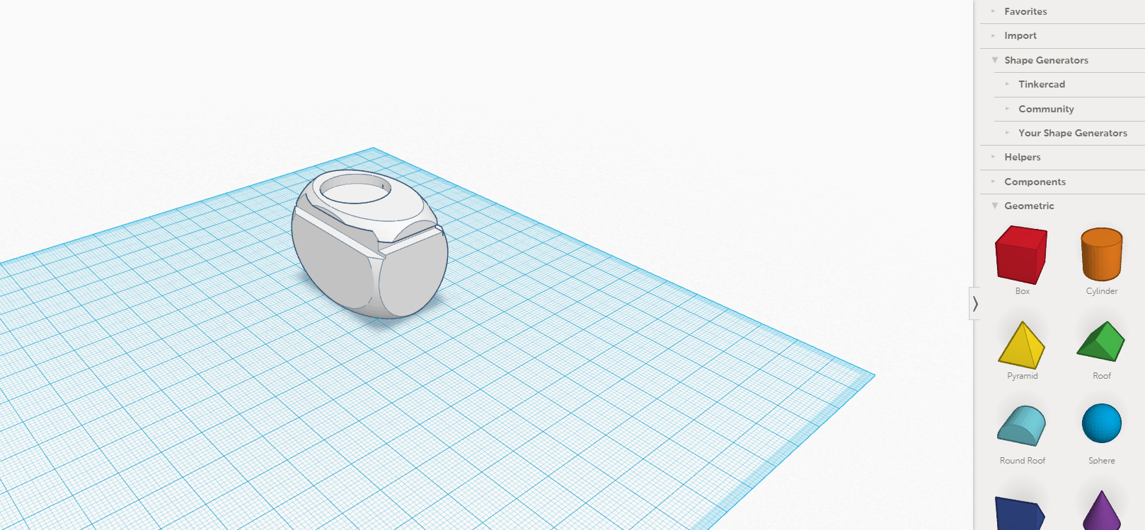
I wanted to make a float that would have the buyancy force to press a plug into a hole, making a ballcock. I decited to design the model in Tinkercad since it was a simple model and quite easy to do for printing in tinkercad.

I just needed to make a simple float, with dimensions 30mm*40mm*26mm with groves on the sides for a frame I'd make in plexi and a circular grove on the top for a plug I'd make by rubber casting. So I started out making what would be the float it self with a dice shape, just so it would have nice smoothe corners. After that I found spaces on the side of the dice, near the top, and made the groves by taking a box shape and turning them into the "hole" function.
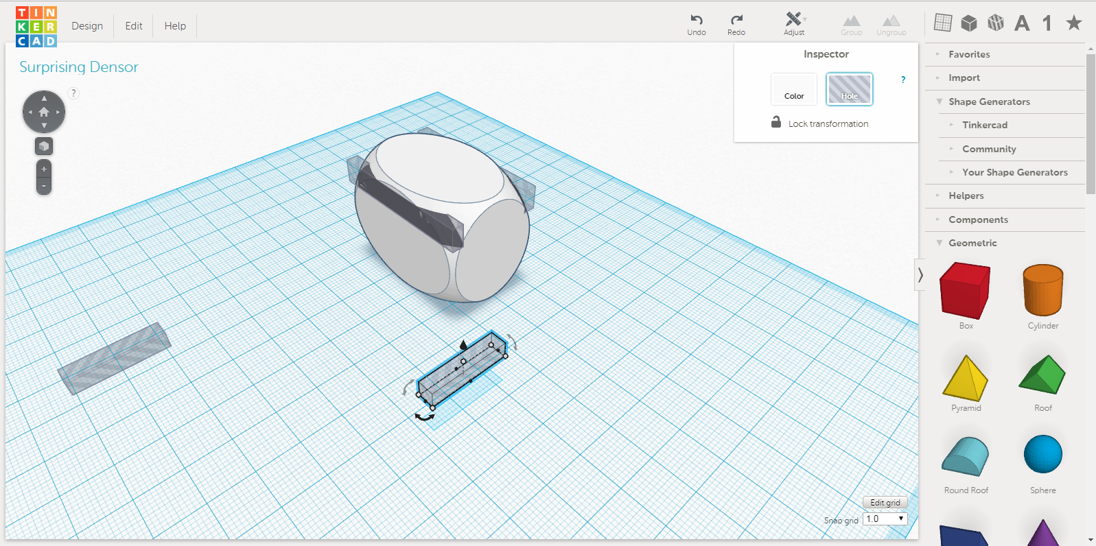
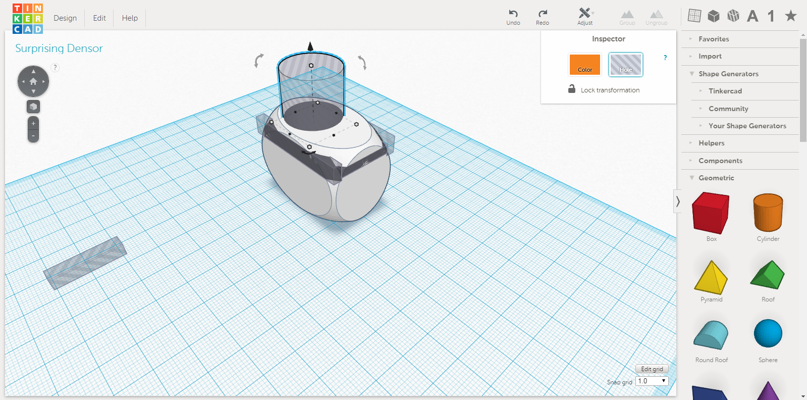
Tinker cad is actually quite nice when working with something this simple. Its runs in browser and allows for interestingly complex structures.
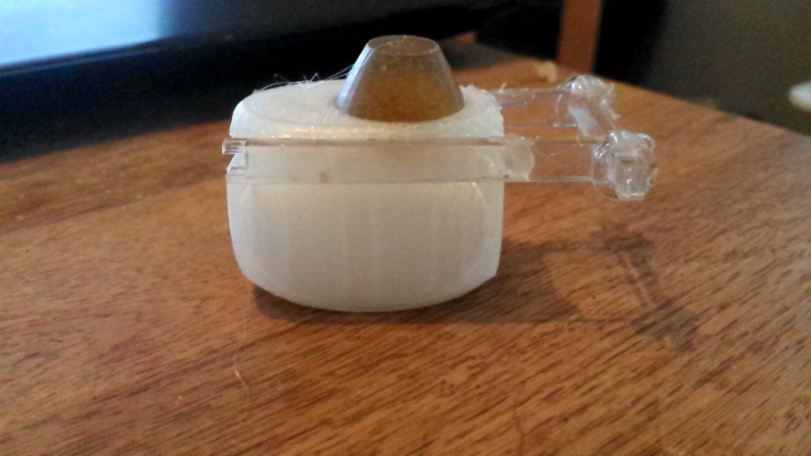
It could've been molded, I suppose, but the time it took to 3D print outweigh the, atleast 4-5, molds that would have been needed to mill and to cast. It took about 30 minutes from idea to working product including the design and drawing.
3D Scanning
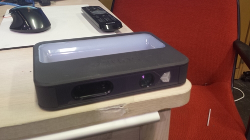
Our scanner is the Sense 3D from Cubify/3d systems. Its the same company as our 3D printer and comes with its own software. We didint like the software that came with it so we've been working with both Skanect and Reconstruct me.
Reconstruct me is an interesting program, user-friendly-ish. When the program is first opened it looks pretty much like this:
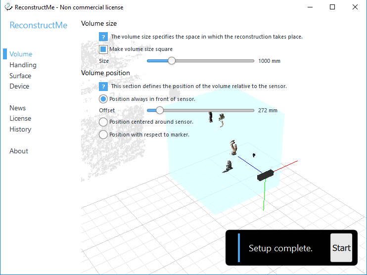
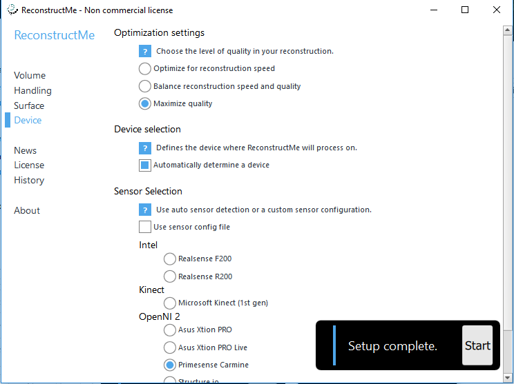
Some parameters can me changed, such as the volume of the object being scanned, the distance from the object etc. We've been playing around scanning our selves with it, but for this example I played around with scanning a vice that I had infront of me during this demonstration. Additional parameters can be set up in the "Device" flip.
Once all of the parameters have been set up, the "start" button is pressed. Its then going to prompt the user with a countdown + an image feed of the current environment. Once the countdown has finished the scanner starts scanning the object in the set distance specified in the setup browser.
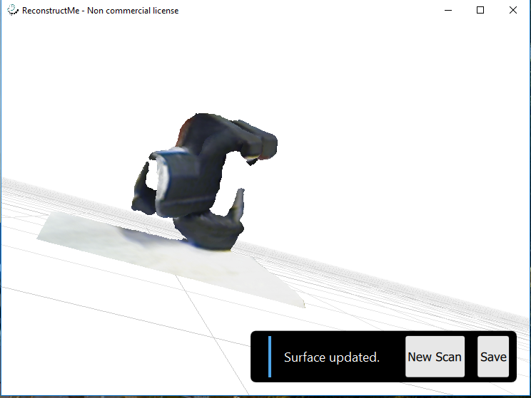
Once the user has scanned in what is wanted, the "finished" button is pressed, the software then renders the file. It gives out a .ply file, which can later be modified.
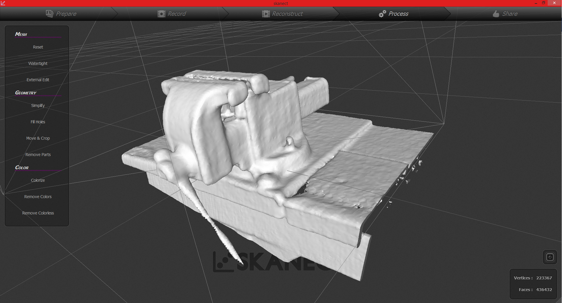
I also played around a bit with Scanect. Its a bit better for when you move the scanner around, and not the object itself. Just wanted to give a sample picture, since the scanning in reconstruct me didint come out quite aswell for the same object.