WEEK 15
WEEK ASSIGNMENT:
Networking and communications
Device connections
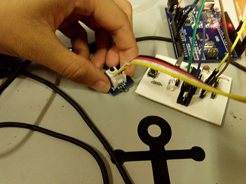
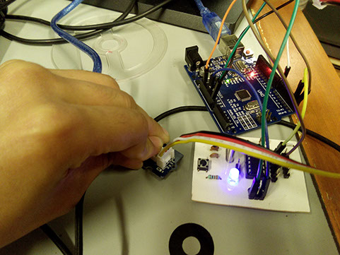
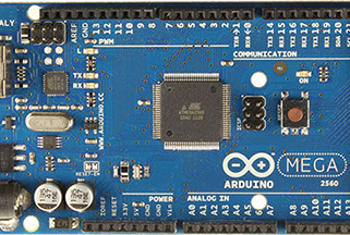
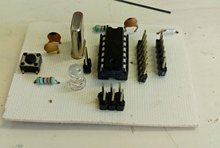
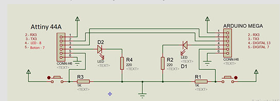
For this week activity we needed to connect two processors, so we decided to use a Attiny44A micro-controller and an Arduino Mega2560 with a button and a LED in each one, so the LED connected to a processor only turns on when the other processor button is activated.
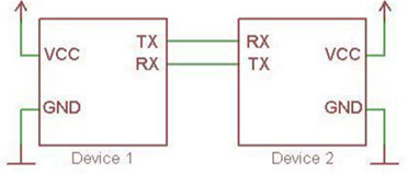
For the Network, we used an Attiny44A and a Arduino Mega 2560. The schematic diagram of the
Serial Network connection:
Attiny44A Code:
#include <SoftwareSerial.h>
SoftwareSerial mySerial(0, 1); // RX, TX
//Variables
int LED=8;
int BOTON=7;
int DATO=HIGH;
void setup() {
pinMode(LED, OUTPUT);
pinMode(BOTON,INPUT);
mySerial.begin(9600);
}
void loop() {
mySerial.write(digitalRead(BOTON));
delay(100);
if(mySerial.available()){
DATO=mySerial.read();
}
if(DATO==HIGH)
digitalWrite(LED,HIGH);
else
digitalWrite(LED,LOW);
}
Arduino Mega2560 Code:
//Variables
int LED=13;
int BOTON=7;
int DATO=HIGH;
void setup() {
pinMode(LED, OUTPUT);
pinMode(BOTON,INPUT);
Serial3.begin(9600);
}
void loop() {
Serial3.write(digitalRead(BOTON));
delay(110);
if(Serial3.available()){
DATO=Serial3.read();
}
if(DATO==HIGH)
digitalWrite(LED,HIGH);
else
digitalWrite(LED,LOW);
}
CODE FILES
This Network uses a serial Network that uses 2 devices connected by a TX and a RX pin connection, this serial Network uses a UART protocol to exchange data, the TX pin of one device transmits data to the RX pin from the other device, and the other device TX pin transmit data to the RX pin from the first device.