Assignments
This week I had a problem following the assignment but I'm considering it incomplete. This is because I didn't get the 1/64" mill bit in time. On the other hand, I consider my soldering assignment complete since I've soldered quite a few times, including SMD, cables and connectors, boards... I'm not such proficient with the air gun, but getting better every time.
But I didn't really lack mill bits, I had access to some, a v-bit of unknown angle, a couple of 0.7mm and a 2.0 mm routing bits. And the MDX-40 isn't really used at the fablab because we use the big one (2000x1000mm) for everything we mill and we always use acid for making PCBs.
Most of the process is explained in the pictures, even when I didn't come with an ISP, I've learned a lot this week and I'll definitely use the MDX this year for PCBs and with the artists in residency at the fabLAB.
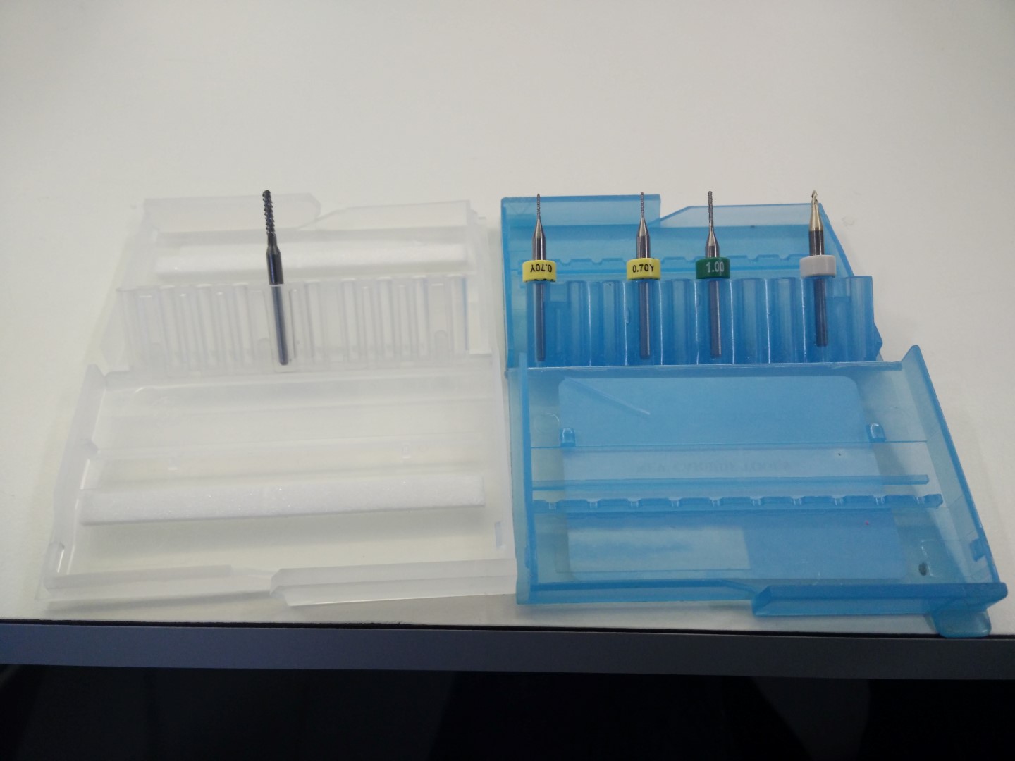
Mills available by now
First testing with wax
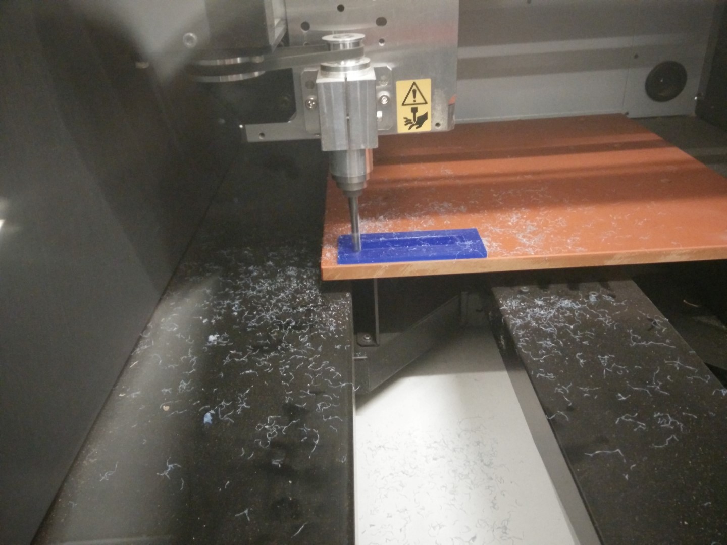
Make it flat, beautiful shades of the milling process.
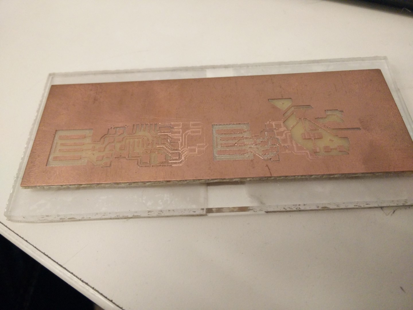
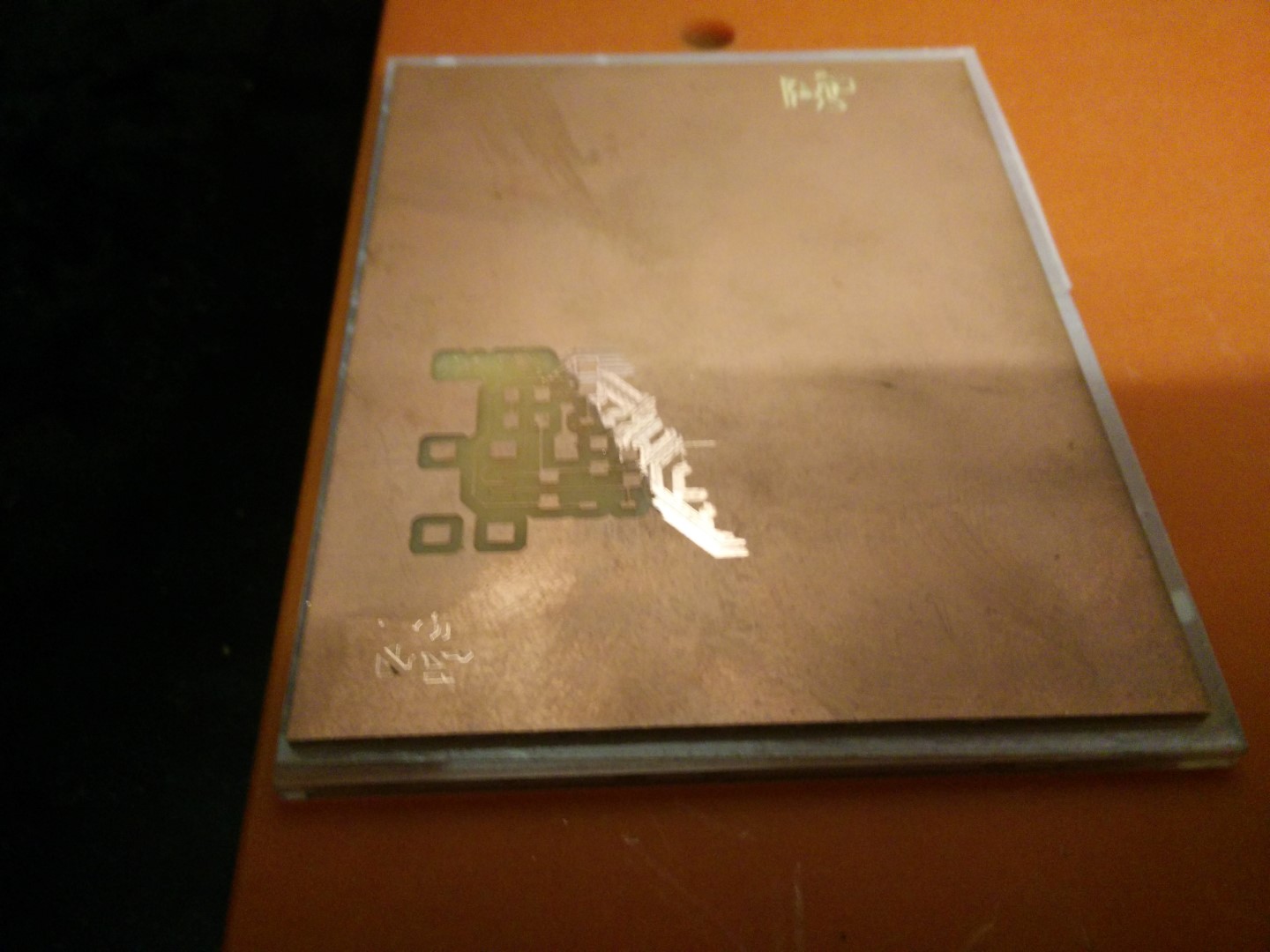
Testing the V bit with PCB traces 1/64" process 0.1mm depth
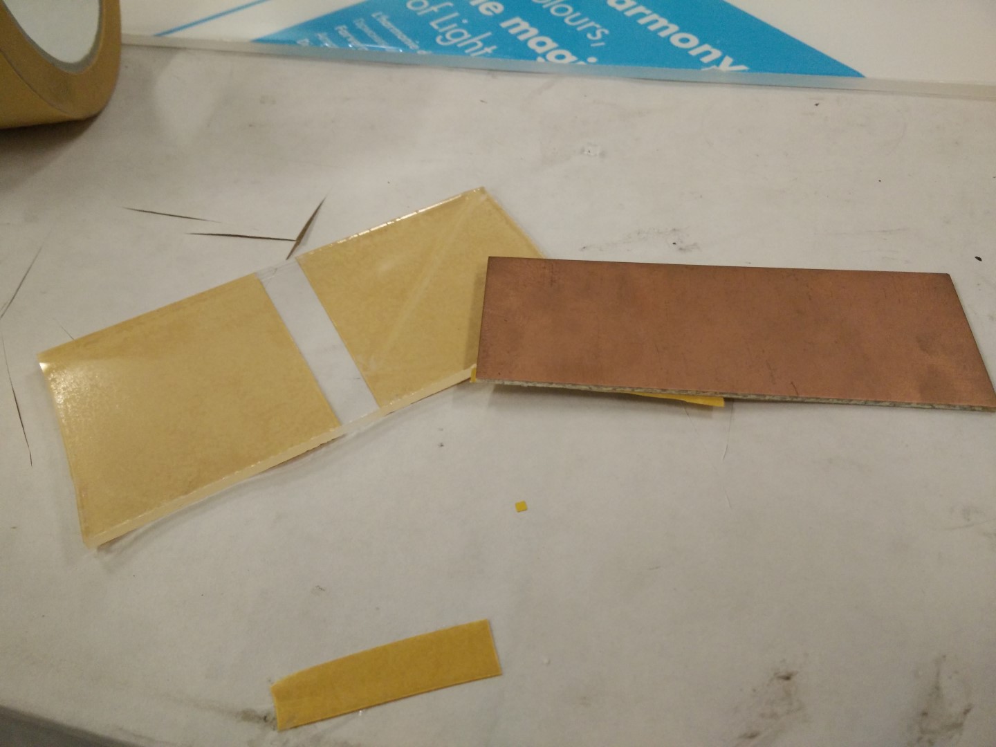
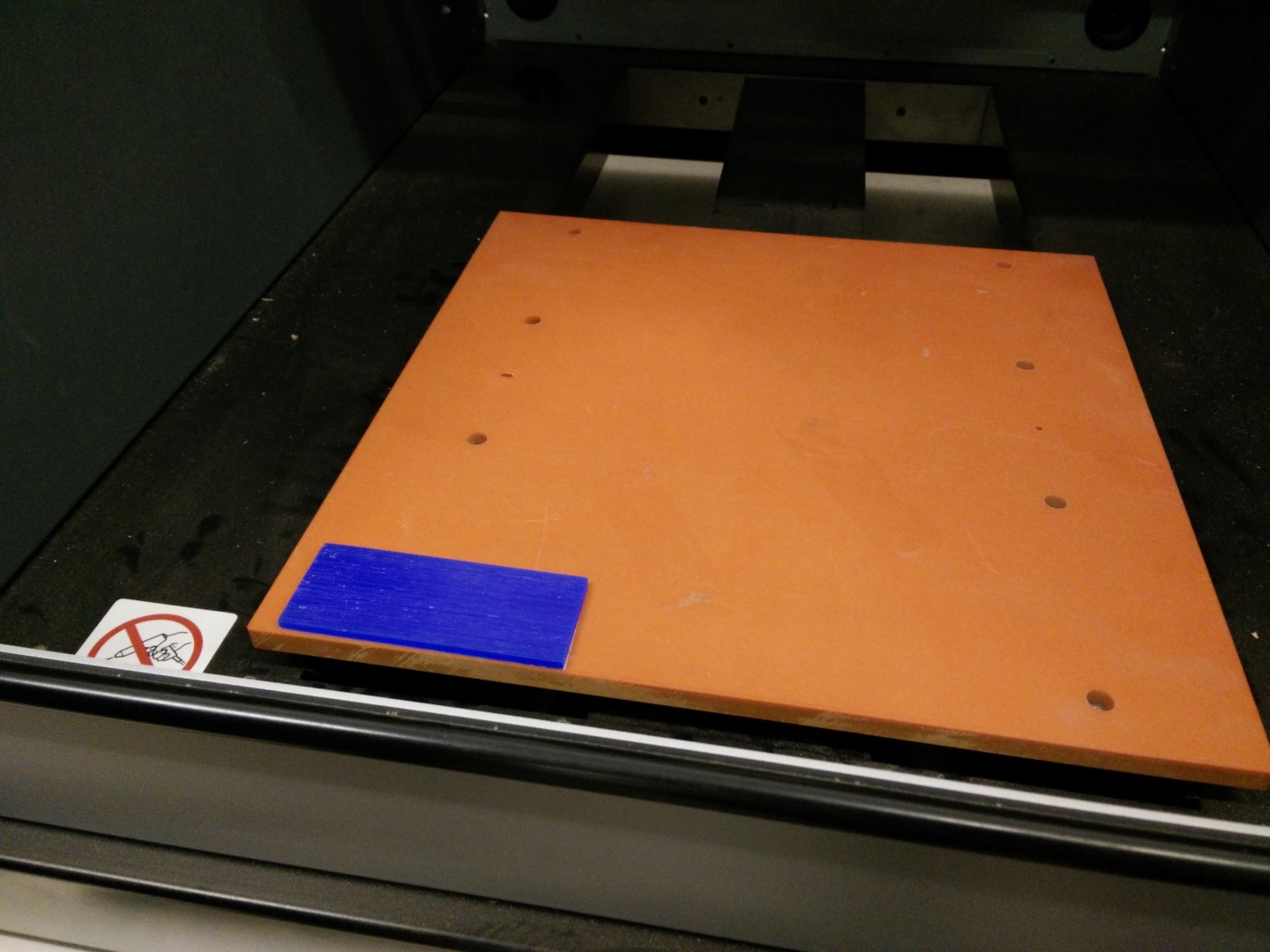
A piece of plexy and a piece of FR1 for testing
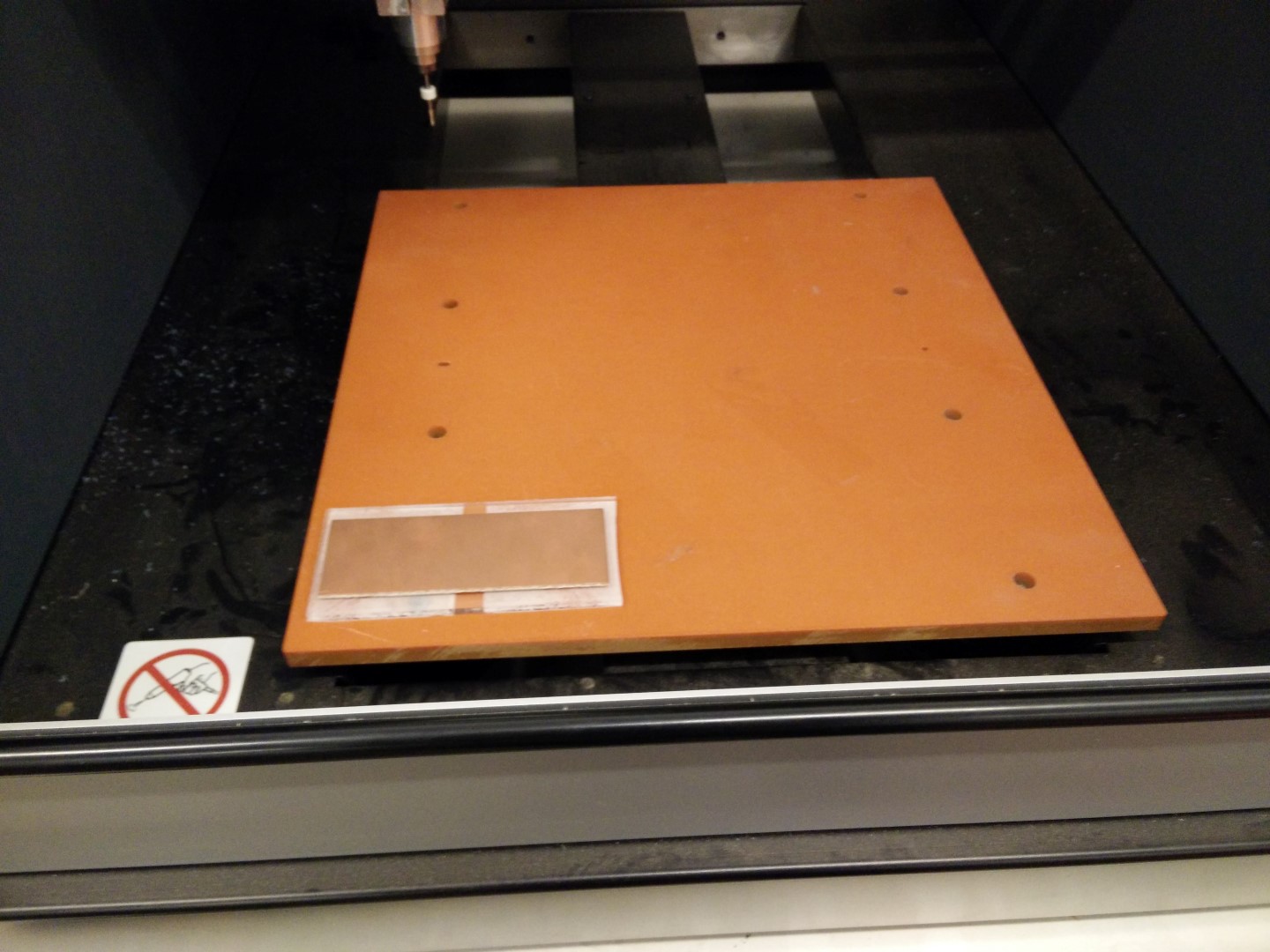
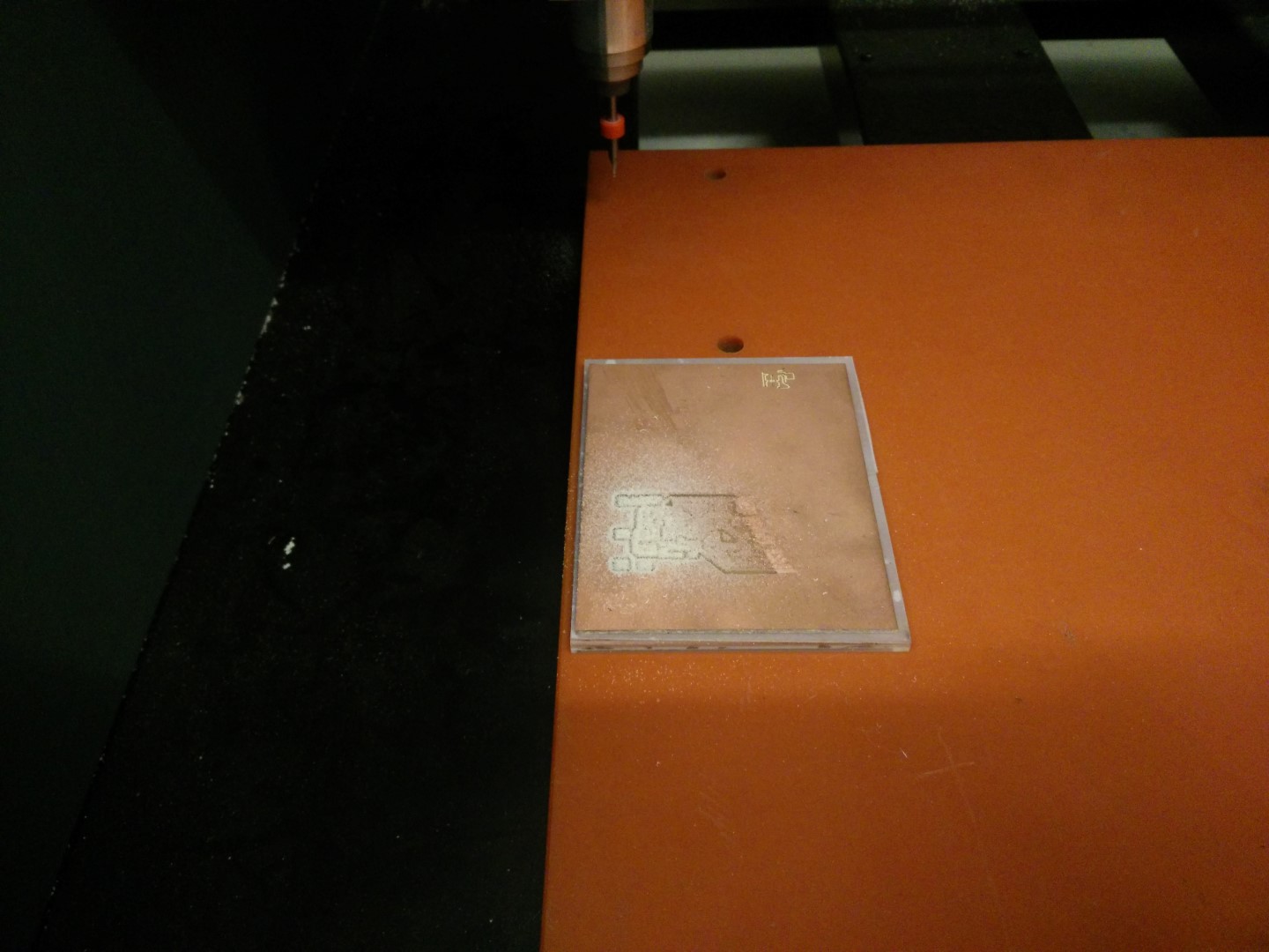
Placement on the MDX40
First result, flatness is critic.
With a V bit the deeper you go, the thicker you get
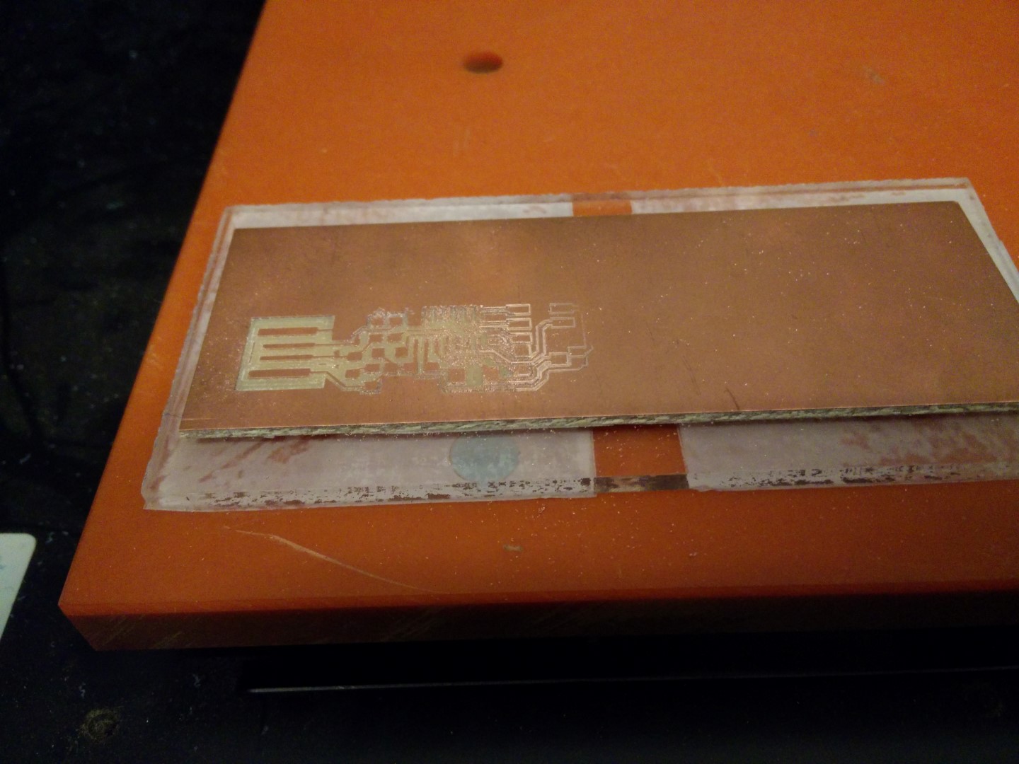
Result of testing different parts of the board and also with the 0.7mm bit.

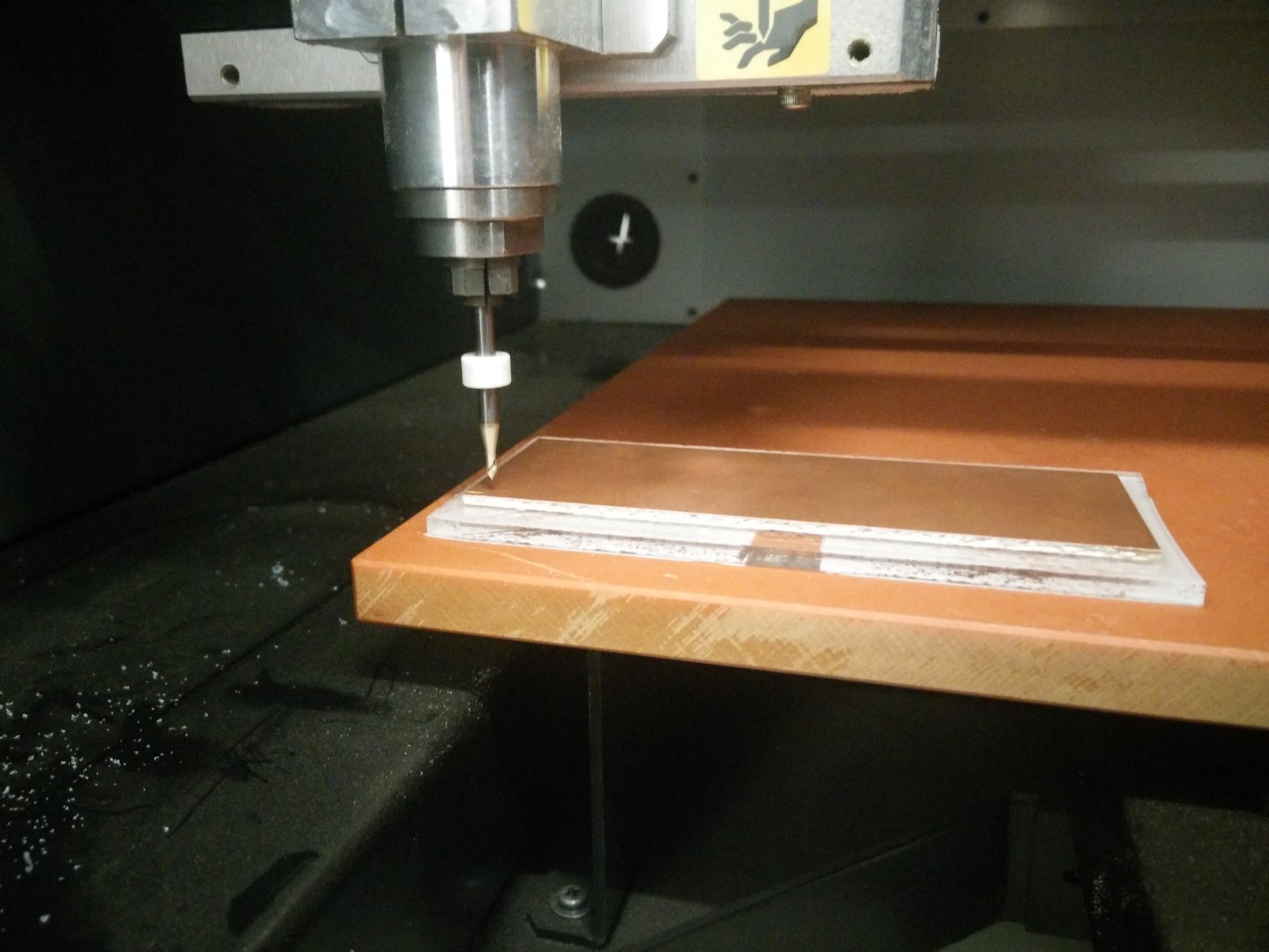
Now is place vertically over the bolts. More flat?
Not bad before cleaning, for a v bit. Still not usable
Another pass a little bit deeper and. This could be fixed and used.
The software stopped during cutting-out. Tried desktop fabmodules, but clearly missed something about the coordinates. I'll try again tomorrow.
Moreover, we don't use fabmodules usually and was a good way to start trying it, even though I didn't connect the machine, just generated the files to the load them into the MDX Vpanel. This is another issue to solve, as sometimes it seems to stop before finishing, at first we thought it was coming from the end of file descriptor or something like that, as the PCB traces are difficult to tell if it lacks some cutting. Then we witnessed how the cutout stopped before finishing. Seems like a problem with something on the code from fabmodules.org This is something I want to keep doing during the fabAcademy and I will come back to this page.
UPDATE! 29/02/16
Well, yesterday was able to finally make a board using 0.4mm mills. Also, David updated the MDX40 firmware after seeing at the MDX support page that Firmware version 1.50 for the MDX-40A. Fixes bugs with thickness of Z0 sensor settings and ability to read H command in 3rd party CAM programs.
So I've started with the fabISP with a 0.1mm depth cut. But the surface it is not leveled at all. But what I was able to do is to use the calibrated Z0 sensor from our big CNC FRH210 with the Roland MDX40. It's a 12mm sensor, but the Vpanel only lets you enter a number between 14mm and 16mm. The solution obviously is to put 14mm, detect Z0 with the sensor, then remove the sensor and move the head so its 2mm. Then manually set Z0. Also, the length of the cable was not enough to reach modela's back panel, so I grabbed a stereo cable I had in hand, and I was mistake-proof enough to grab a broken bit to test the extension, being a stereo cable. I was right and wrong because it failed and had to change the tip and ring because modela reads the tip of the jack. I'll get parts to make an extension cord.
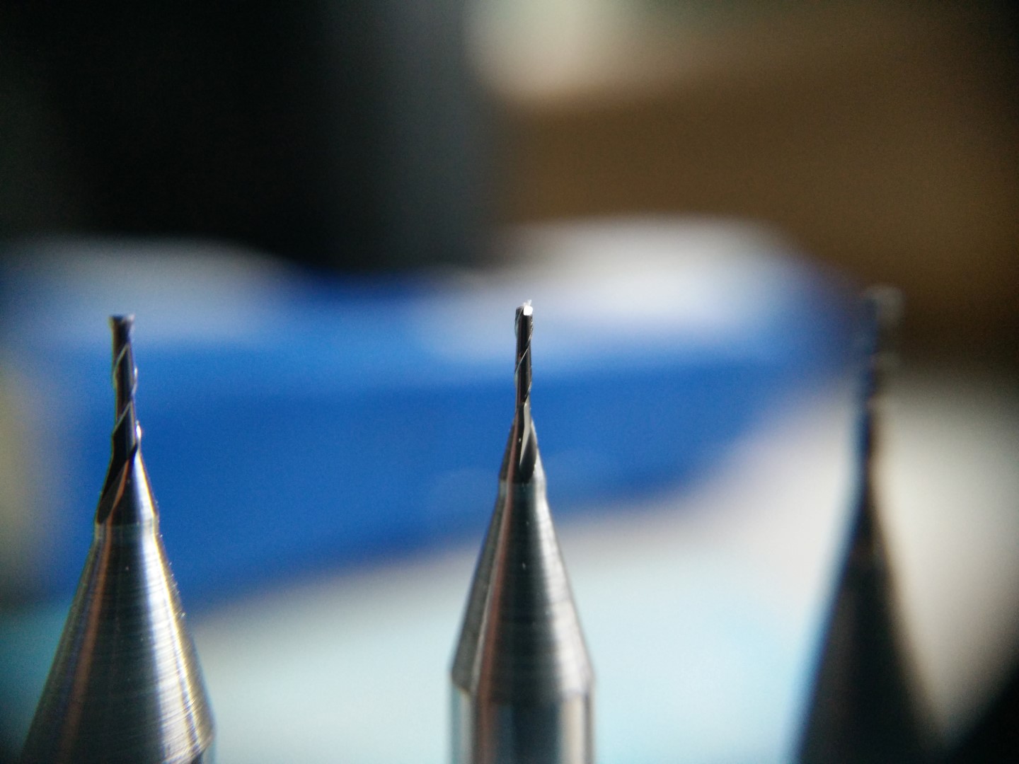
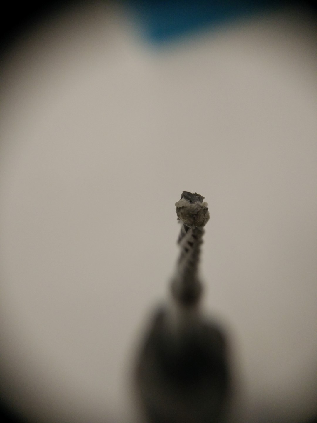
Detail of the 0.4mm bit
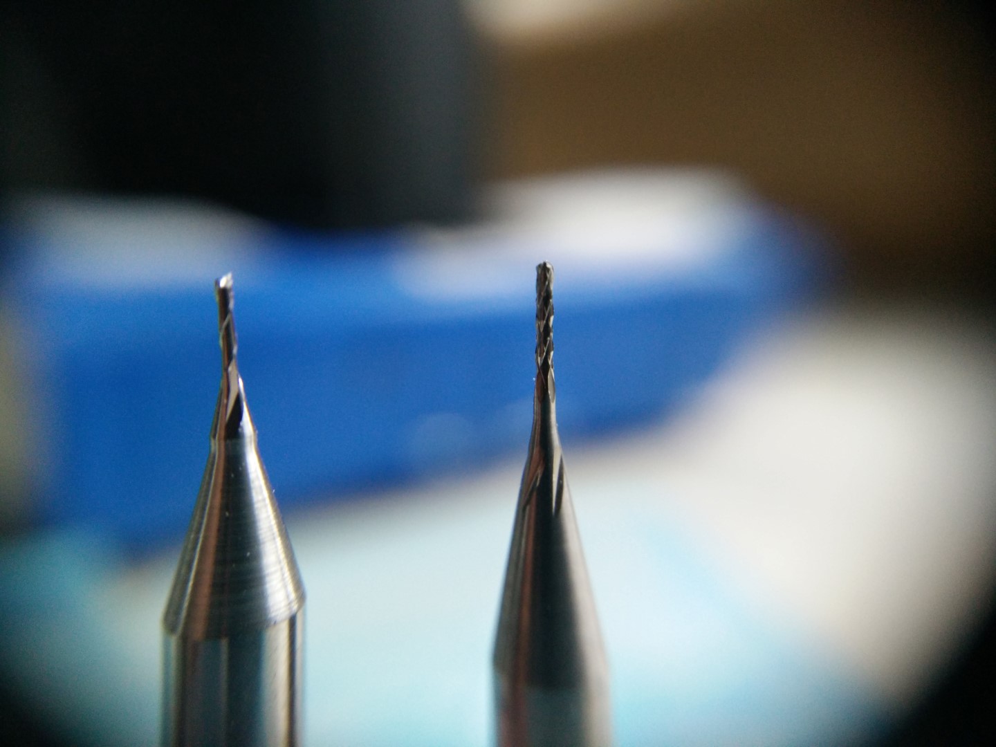
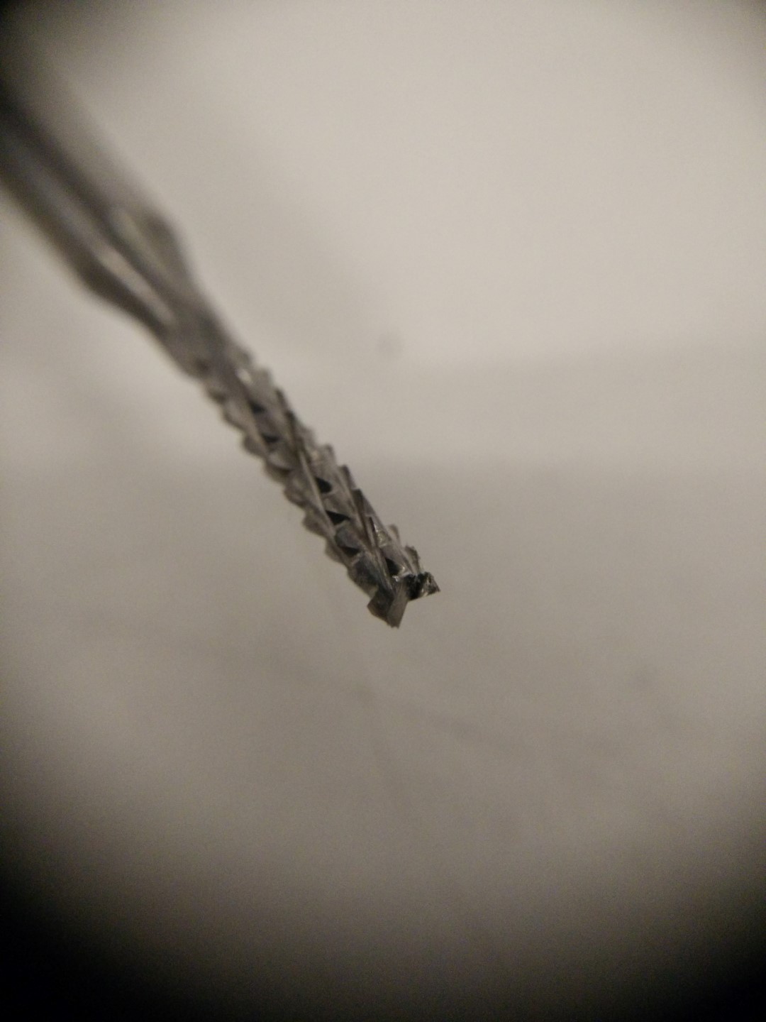
Detail of the 0.5mm bit
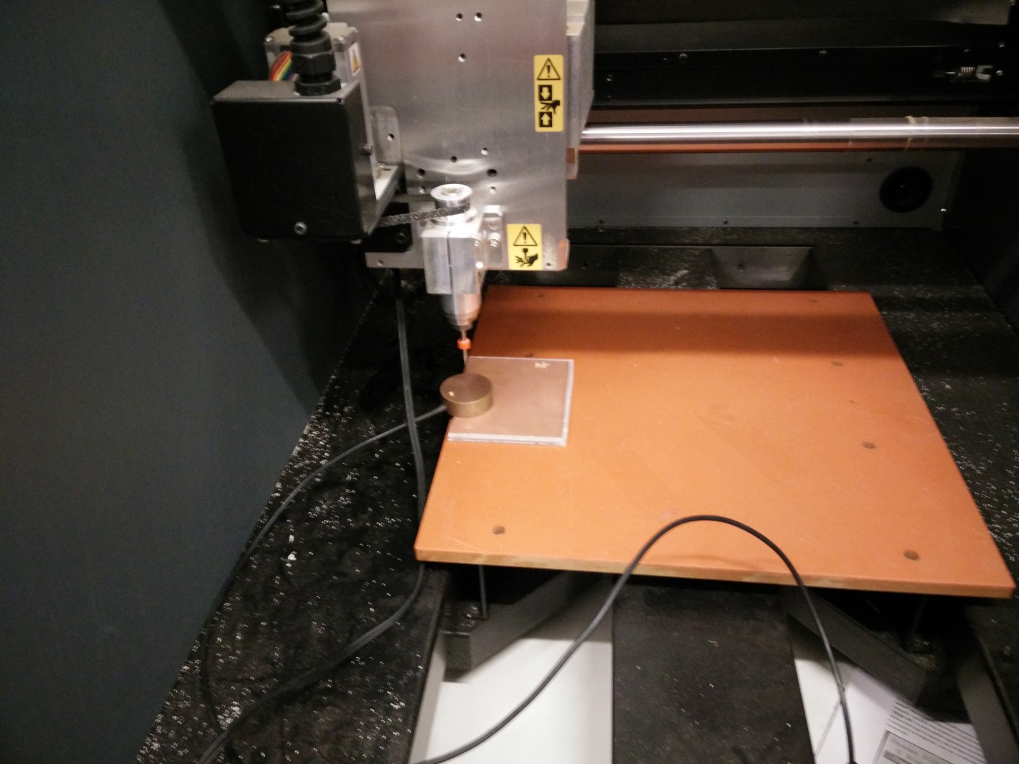
Using the Z0 sensor
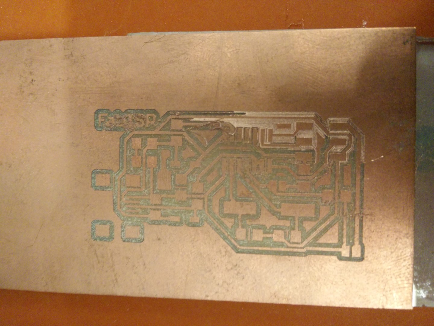
Bed completely off-level, 0.1mm pass
0.2mm pass, seems like constant slope
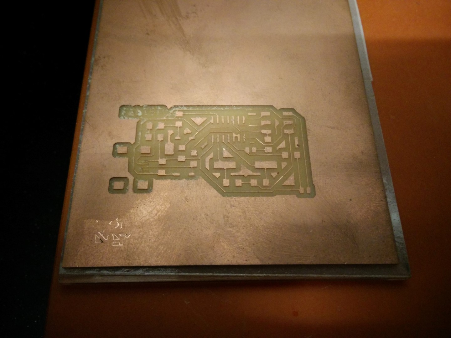
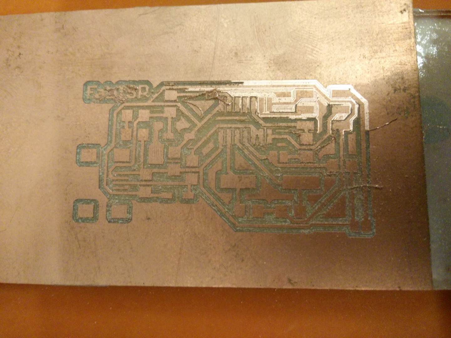
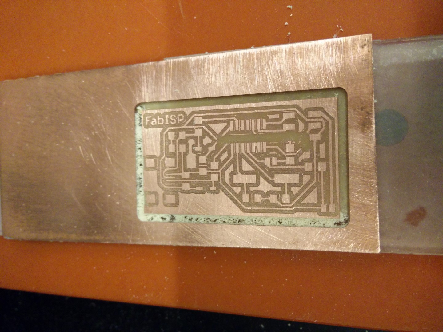
0.32mm pass, all pads semm ok, FabISP logo is ripped and so are a couple of the usb connector pads
Milling it out with a 2mm routing bit
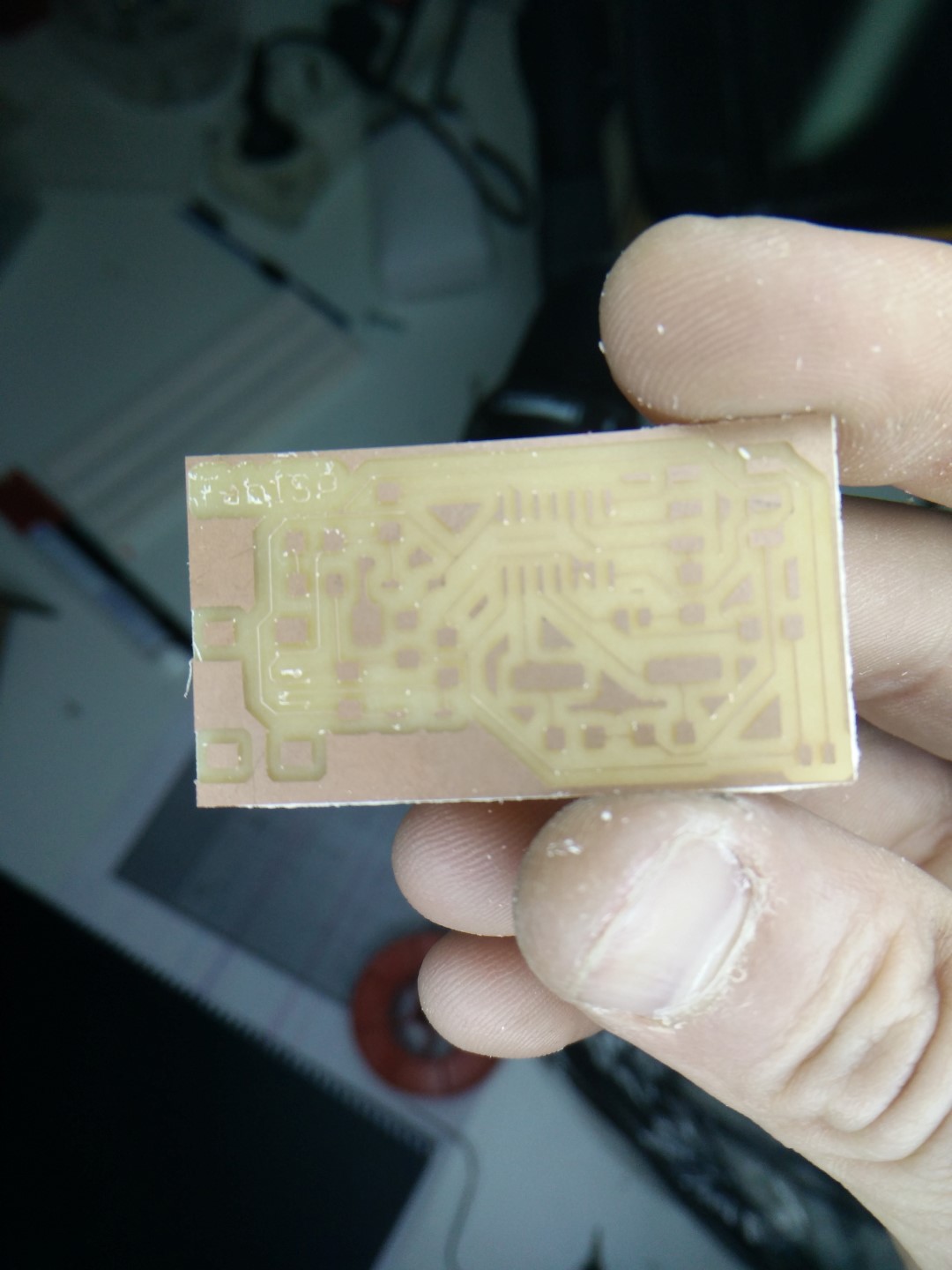
Could be used but I can do better!
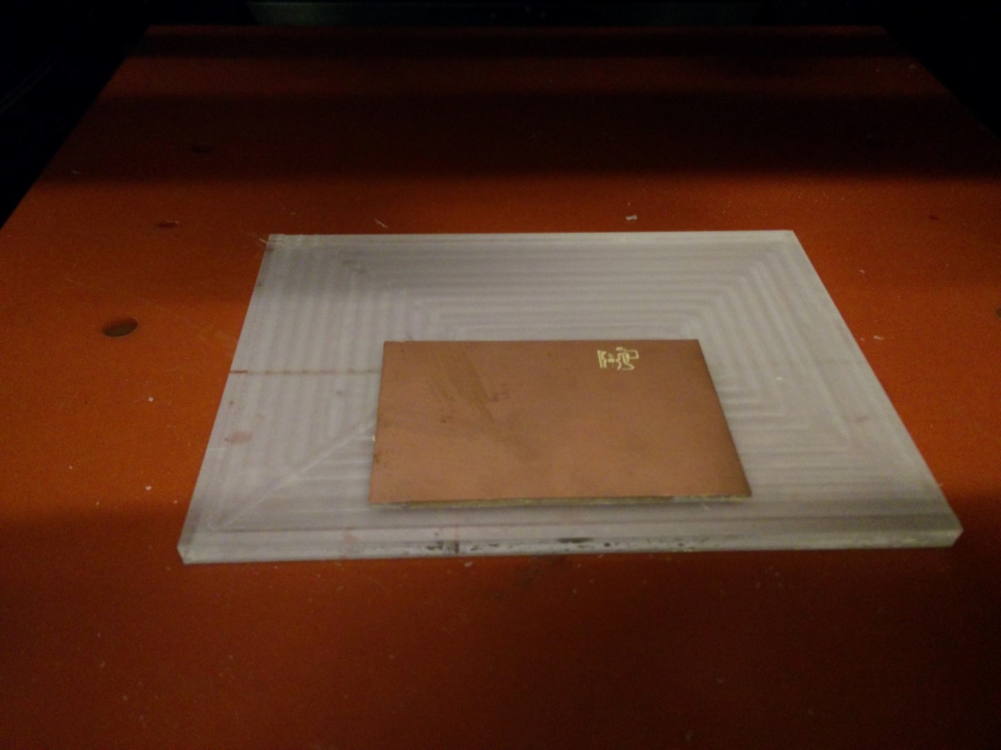
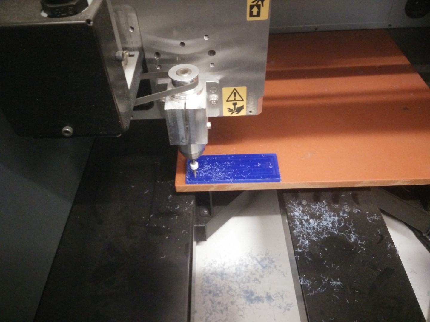
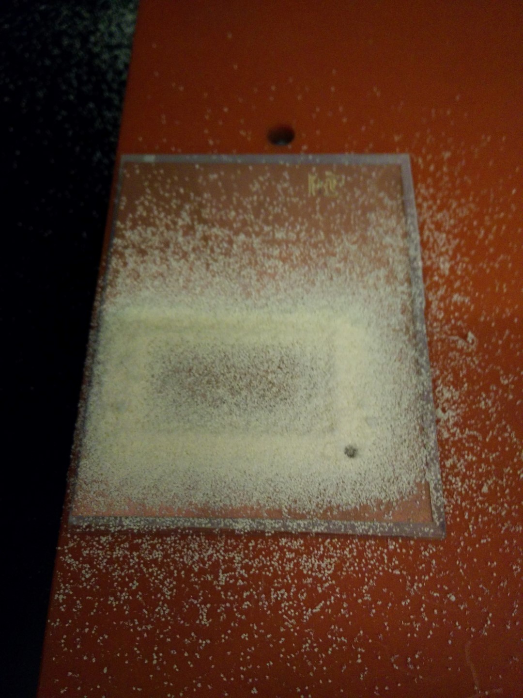
So, took a larger PMMA piece and flatten it 0.5mm
Macro detail of the flattened surface
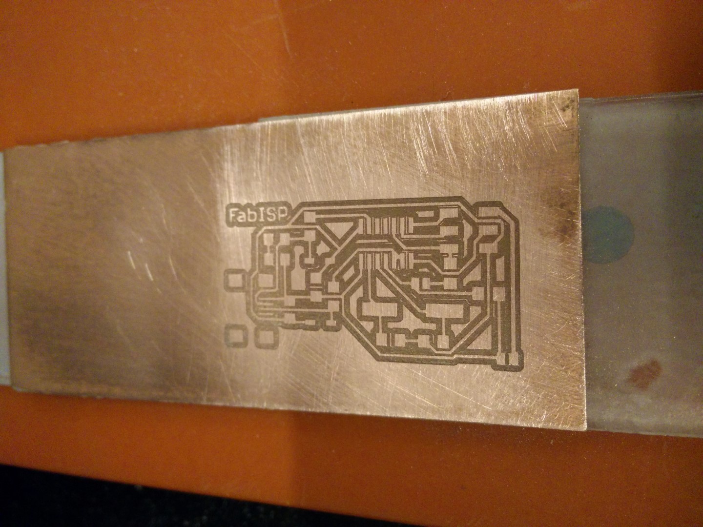
Now this looks good!
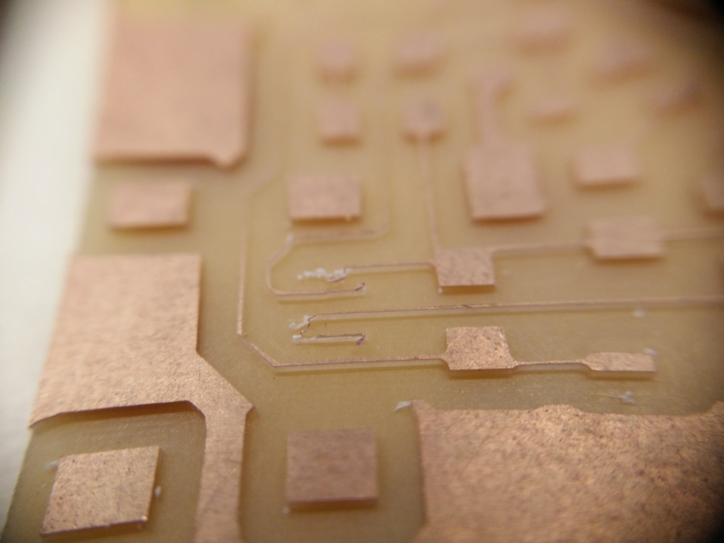
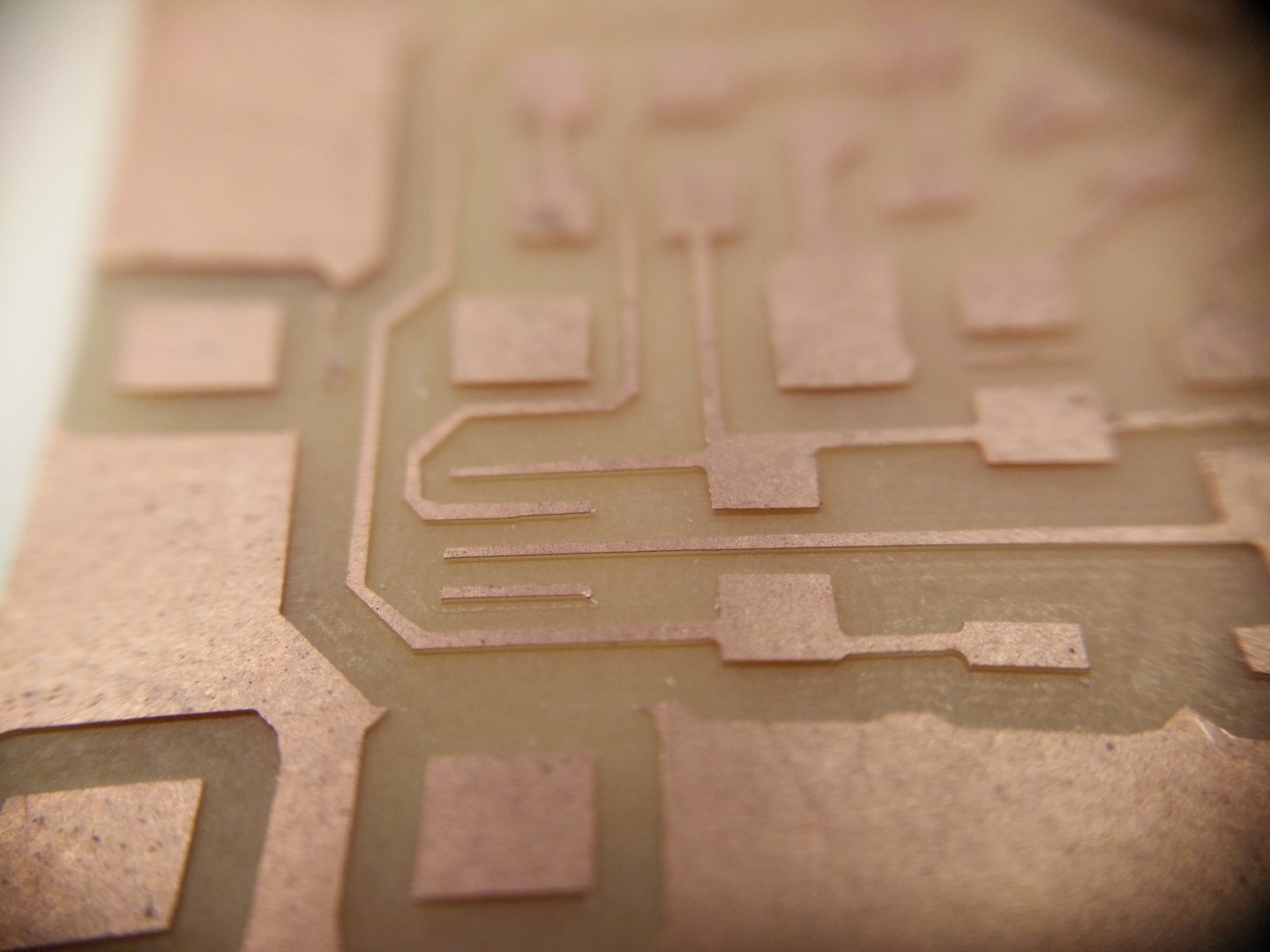
This would have been a bit of a struggle to solder. Notice how deep are the traces here
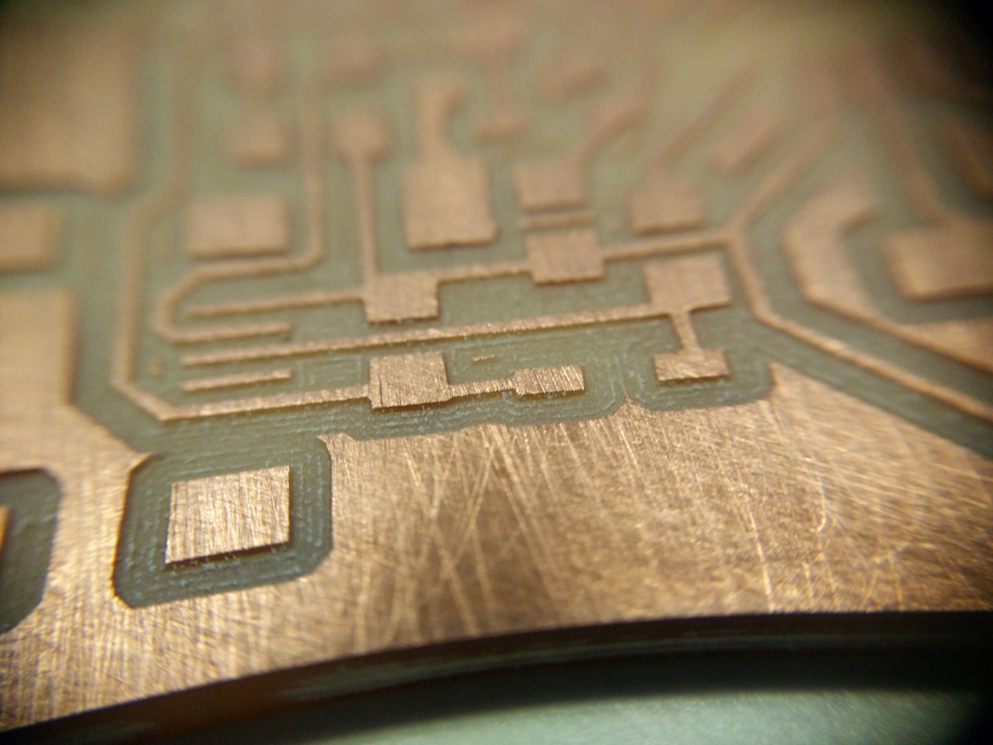
This is a macro detail of the first board machined with the V-bit
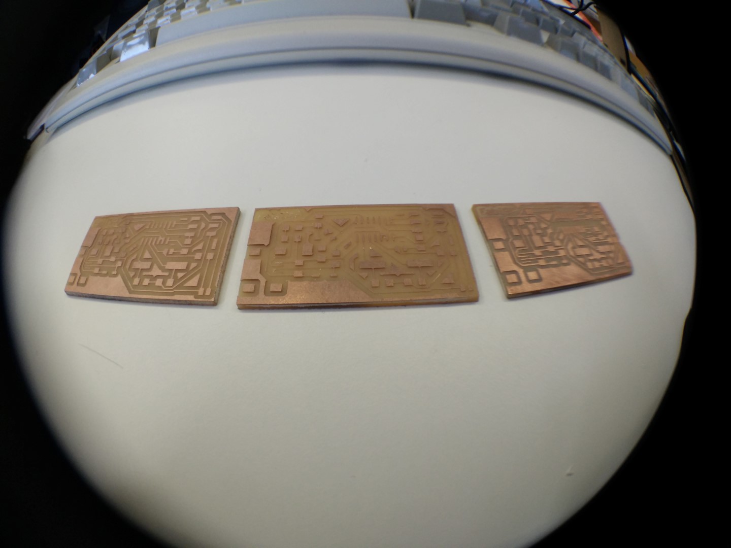
Left to right, newer to older

Fish eye is fun, but macro is coming in handy. All photos here are taken with a phone camera. You can get those lenses on eBay or Aliexpress for around 5€.
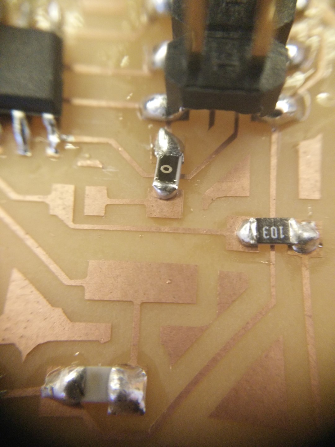
It was some time ago since I soldered SMD. Not my best solder for sure. Lots of solder!
When I finished cutting out the PCB, there was a lot of residue from the double sided tape on the tip of the mill. So I picked up a mill box and poured a little bit of acetone just to cover the tip of the mill. Today in the morning I just shook it a little bit and it came like new.
By the way! I don't have a good phone camera, but this was made with those cheap clip-on lenses selling on bazaars (online bazaars I mean) I got a 3 pack for about 4 or 5 EUR and it includes fish-eye, wide angle, and macro lenses. Fish-eye is funny, but macro is really cool to show Neil your solder skills and other fine details
Lots of glue from the double sided tape
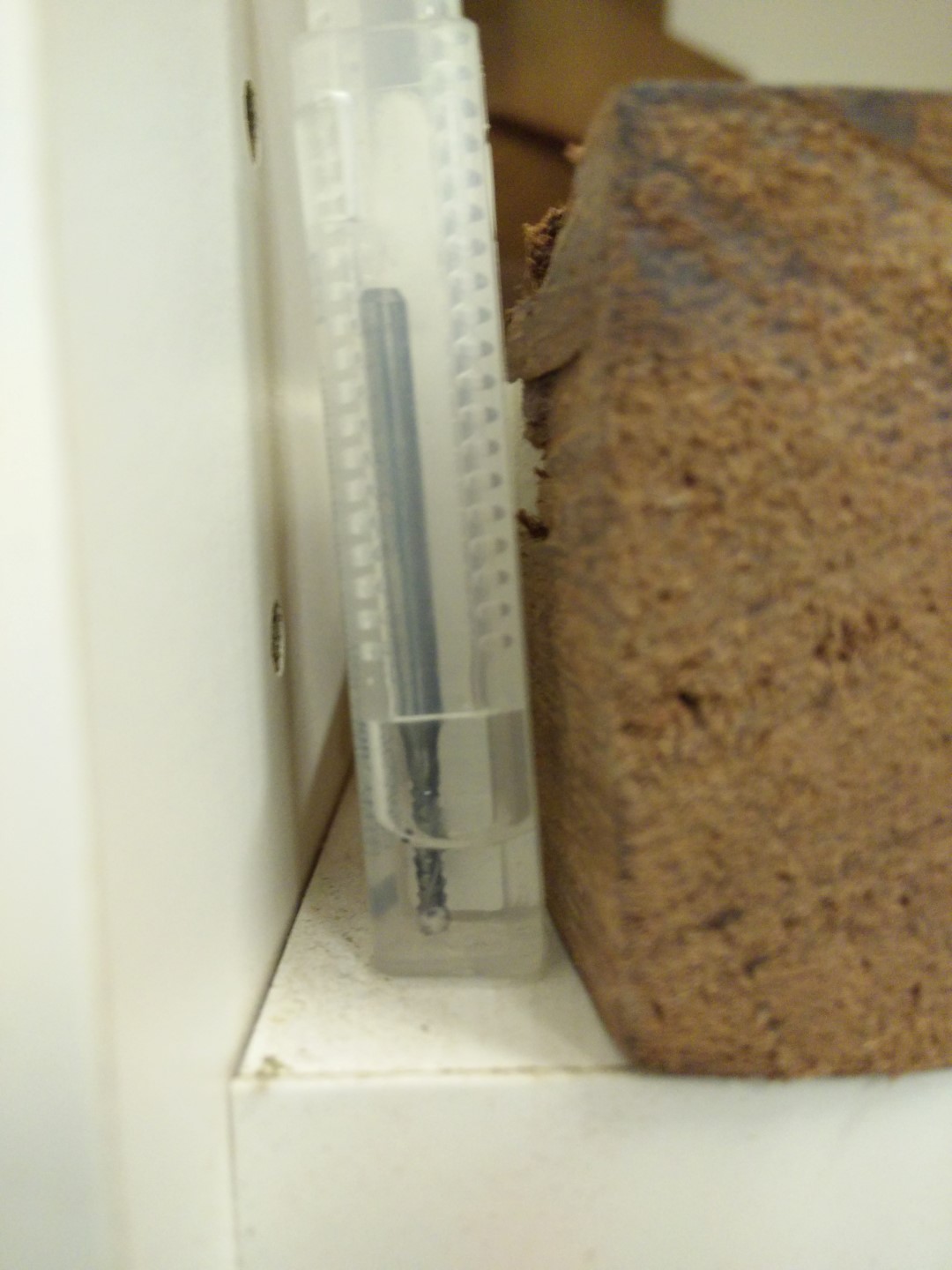
Soak and wait!
I didn't even touch it, just shook it before getting it out the acetone
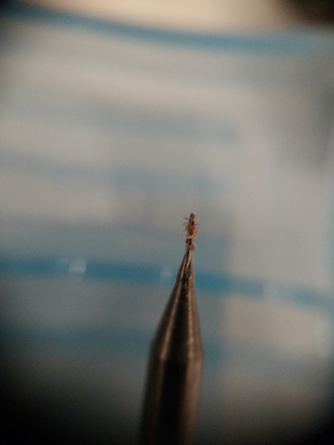
Copper on the 0.4mm mill, just remove carefully.
Update: I've been a bit behind with electronics production because I was having difficulties to get some SMD components. But this week finally completed my fabISP board and programmed it. I've used a USBasp programmer, wrote the fuses then the .hex and now I have to check if I can program other boards with it, but that and other problems with the workflow comes in the updates on week 6.
Once the board was ready, I needed another programmer to flash the fabISP firmware into the µC. For this I've used a USBASP programmer by Thomas Fischl. Though my programmer is a Chinese version that you can get for as low as 1.35€. This programmer has a 10 pin connector and usually ships ship a 10 pin ribbon cable, but you can use just your breadboard cables (aka dupont cables) to connect them to your ISP connector. You can also get an adapter for a few cents more (or you can just make your board).
Also, not mentioned, I've installed AVRdude a program to talk via serial and program multiple ATmel's AVR µControllers. Once installed, I went to my terminal, which in my case is Cygwin, but can be the command prompt/system symbol but I strongly recommend using Cygwin. And then check for the installation on the PATH by just typing
avrdude
To check also that there is communication with the µC I add a couple of parameters to tell avrdude what to look for and I input:
avrdude -P usb -p t44 -c usbasp
This is also valid:
avrdude -Pusb -pt44 -cusbasp
For most cases, default fuses should be ok. Fuses are a set of flags on the microcontroller relating the inner working of the chip, like if the internal oscillator is enabled, if its pre-scaled. One easy way to get your fuses right is to use a calculator like engbedded.com You can just check what you want, and get the hex values for those fuses. That are new parameters to our avrdude call, including previous ones about the programmer, and the µC. -U is a memory operation then comes the fuse name, then :w: for writing, then the value, then the format, being "m" for inmediate
(from avrdude docs)-m immediate mode; actual byte values specified on the command line, separated by commas or spaces in place of the filename field of the ‘-U’ option. This is useful for programming fuse bytes without having to create a single-byte file or enter terminal mode. If the number specified begins with 0x, it is treated as a hex value. If the number otherwise begins with a leading zero (0) it is treated as octal. Otherwise, the value is treated as decimal.
avrdude -Pusb -pt44 -cusbasp -U lfuse:w:0x6a:m -U hfuse:w:0xdf:m -U efuse:w:0xff:m
Last thing is to get the .hex file, that is the program in hexadecimal that can be found here along the source code. For that, we can go to the directory where it is and call avrdude again
avrdude -Pusb -pt44 -cusbasp -U flash:w:filename.hex
That should upload the program and start executing it. If you have problems at first check connections then triple check connections (not only correct connection but also no shorts between the ISP lines). Also sometimes a bit of electromagnetic noise or a bad connection can be interfering, it is safe to get 3 "check connections" in a row before getting really to check connections although 99% it is a bad connection.
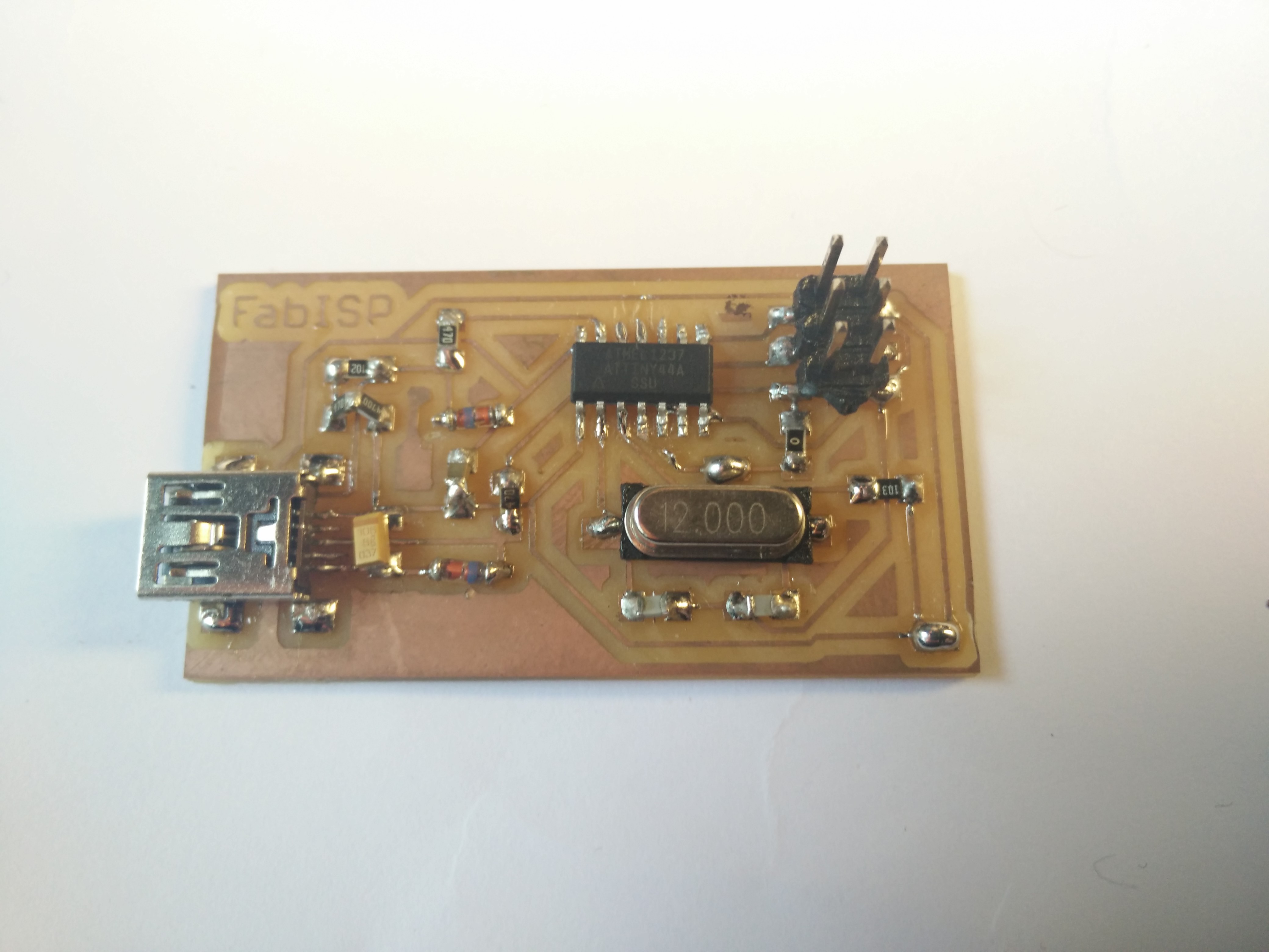
The populated and programmed board
Video
This video demonstrates the fabISP working. I'm using the already programmed helloKiCad board from week 6 and I'm not programming it, just calling avrdude on the parameters needed and getting the device signature, which is the "Hello World!" of the process of programming a board with an ISP, just to see if it detects the target and gets a correct signature.
Machines and software used
SO: Windows 10avrdude
fabmodules.org
Roland Modela vPanel
Roland Modela MDX40
0.4mm PCB routing mill (traces) (default parameters) (4mm/s, 0.1mm cut depth)
2mm PCB routing mill (outline) (default parameters)