Week 14: Composites
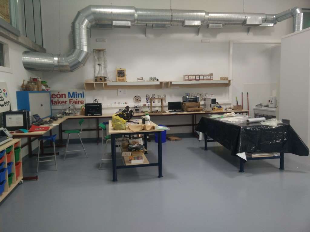
Back to León this week!
So for this week assignment, we shall make a 3D mold and then use burlap and epoxy to make a part. In the last three years, we've done a couple of composite thing at fabLAB Asturias. First was a project for making a fixed wing RC plane 3D-milling the wing and fuselage. We used fiberglass and epoxy to cover the foam, but just that with no mold o vacuum. So one of my first thoughts about what to do this week was a plane fuselage or wing. But using burlap I don't think the results would be very good. Yes it would fly, add a couple of control surfaces and enough thrust to a brick, it flies lovely I'm sure.
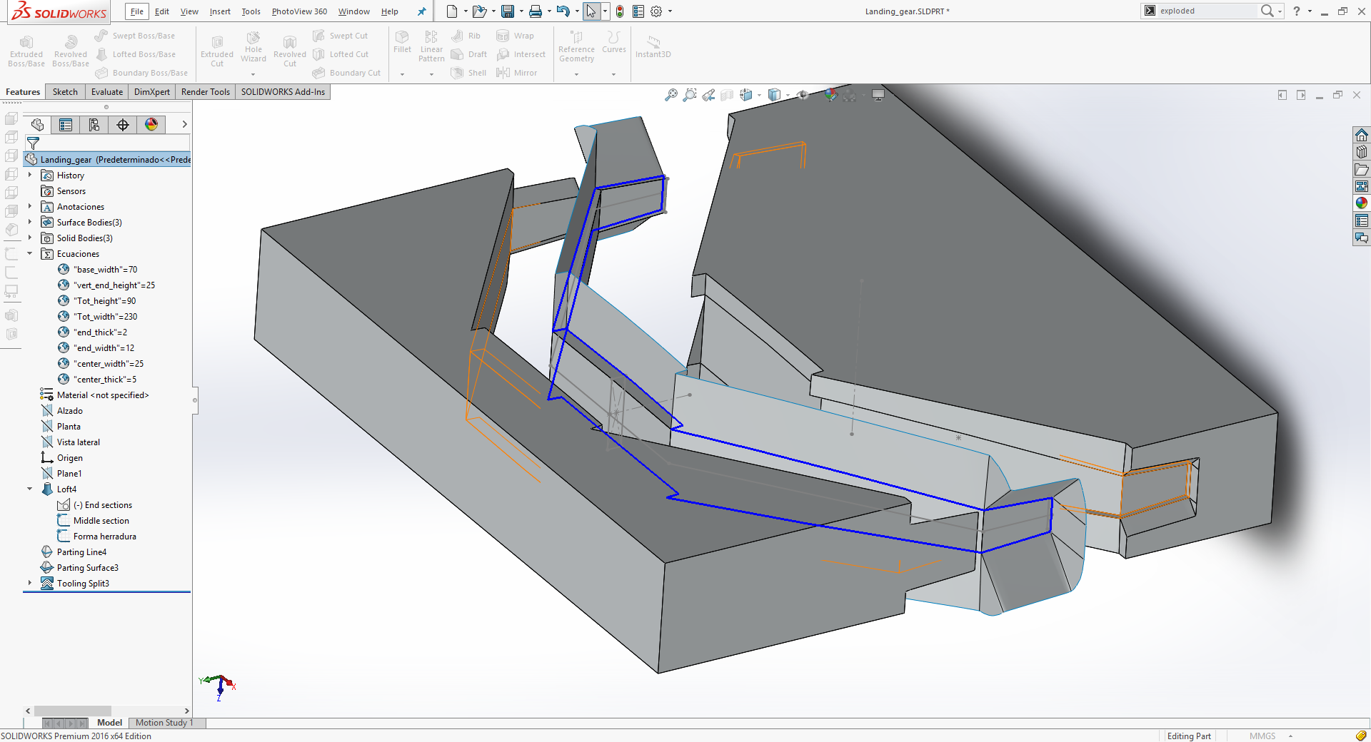
Also, when I was in the design process, David suggested to make a landing gear, and for that burlap would be great. But that would need a 3D model, the best way to do it would be to get the 2D shape out of laser slices and then lay the layers and add pressure. I'm going to do it anyway, but I needed something a bit more complex to check the 3D milling process (that I've already covered on week 7 when I still was working at fabLAB Asturias) and try to make it a 2 part mold.
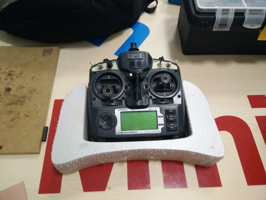
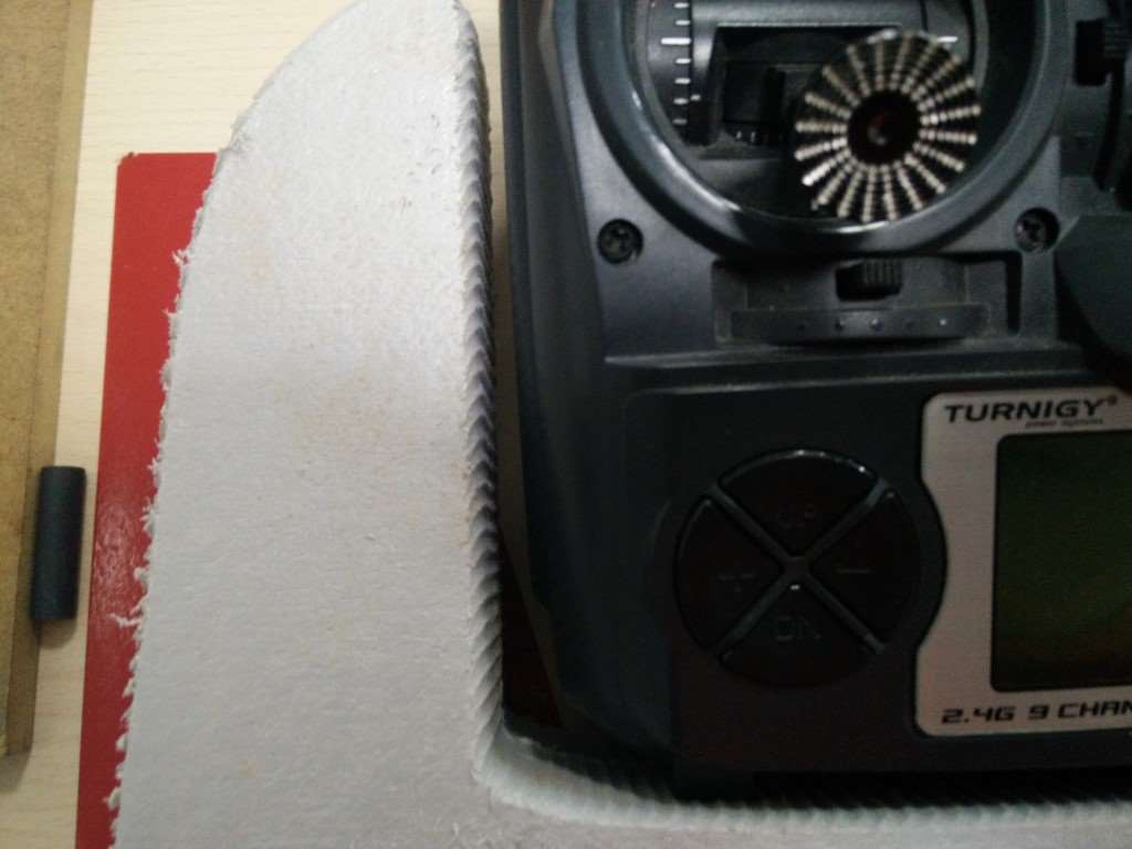
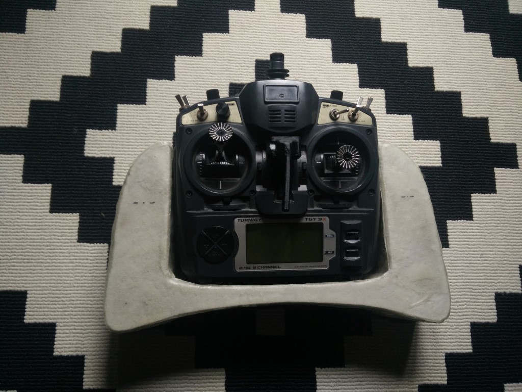
Another thing I wanted to do is to get to do a couple of tutorials on mold making on SolidWorks, basic cavity, and core molds. I've started with the landing gear part and made the whole process to get a mold, understanding what is needed to be defined when using the mold features. Then I got another idea that would suit this assignment, to make an RC transmitter tray for the Turnigy 9X.
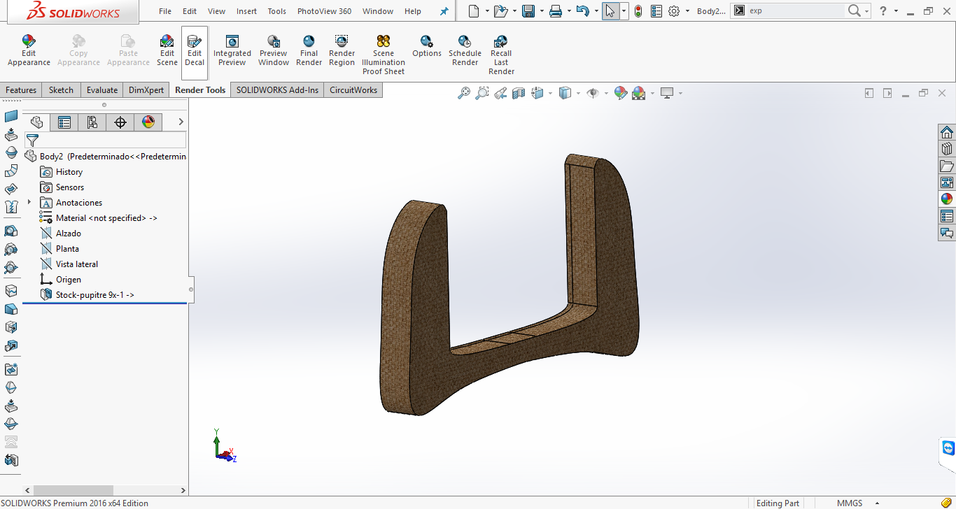

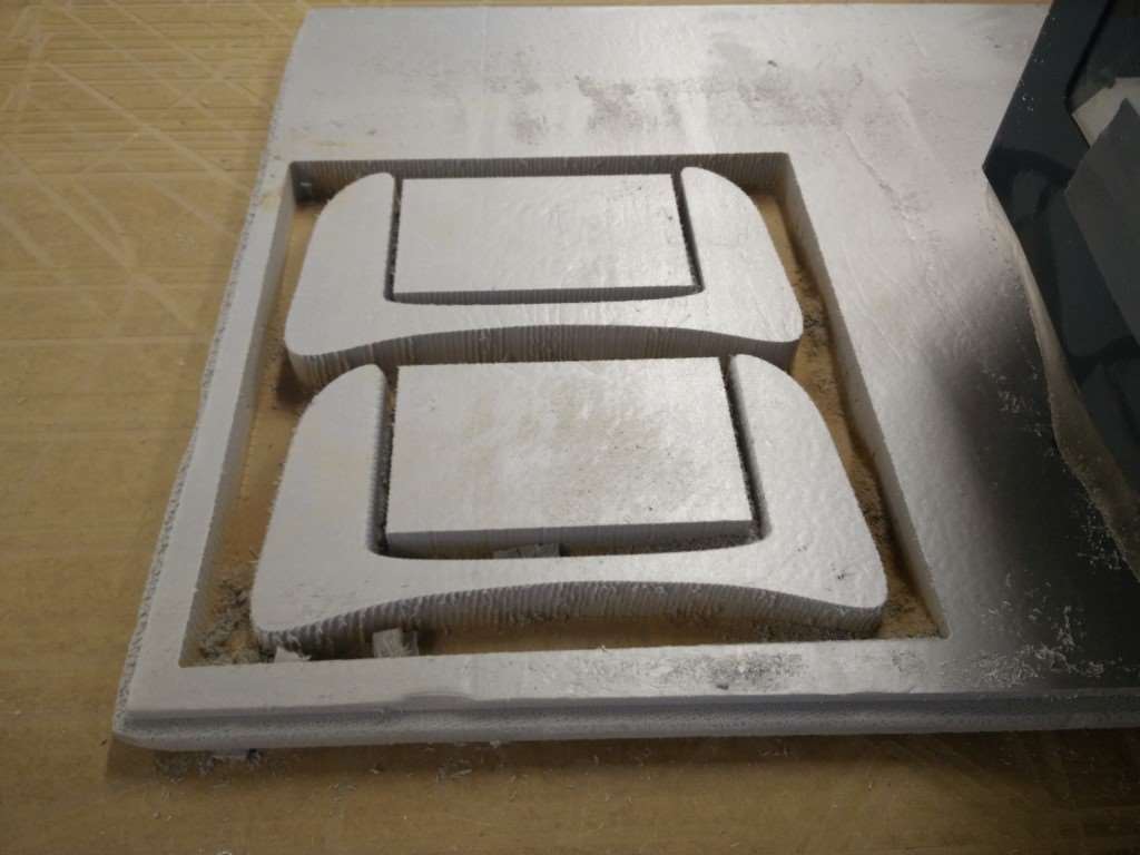
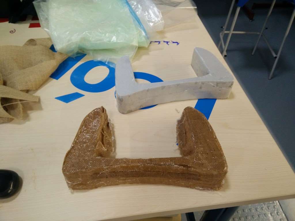
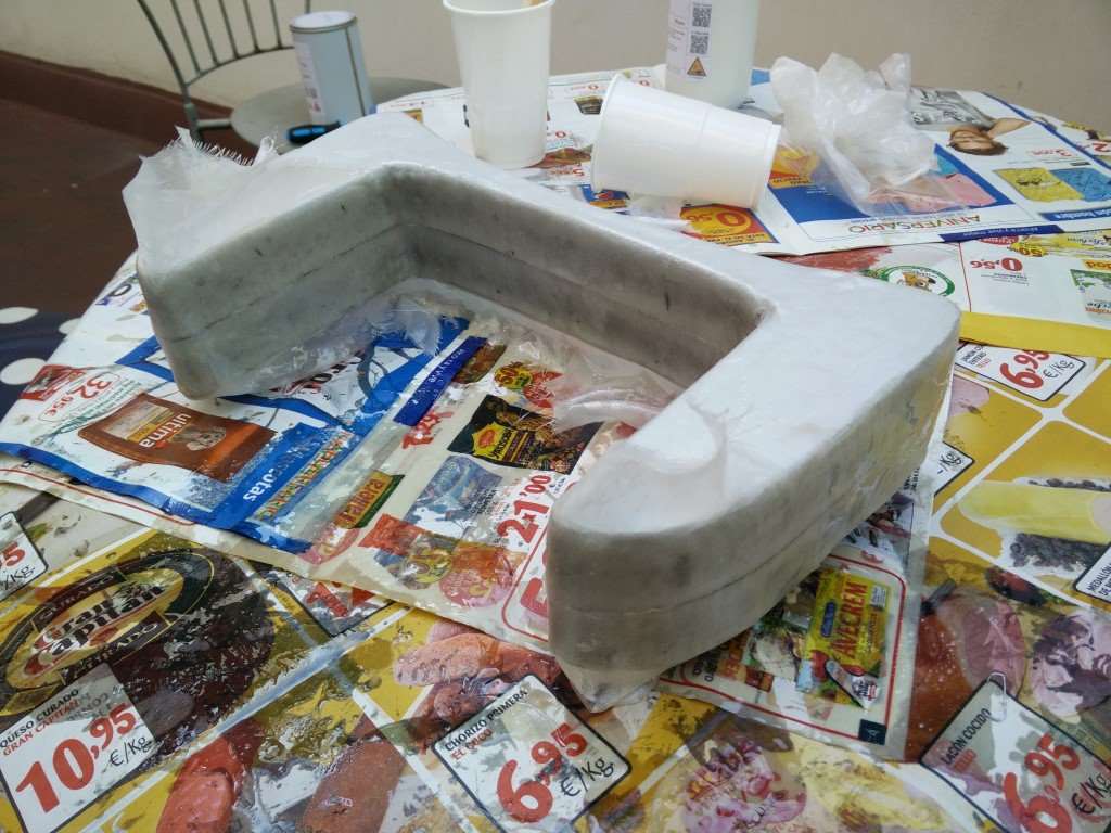
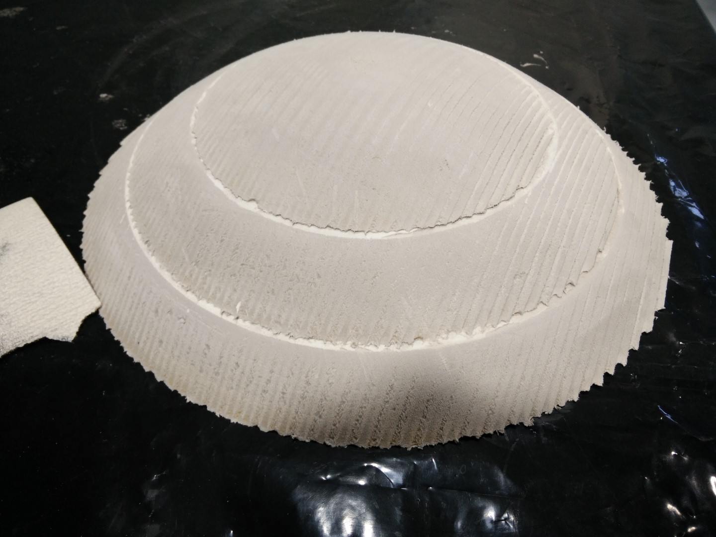
Update: back from León, and it was a bit of a fail. I didn't get to complete yet the composites practice, successfully I mean. I got to Fab Lab León on Monday morning and started by milling the foam to make the 3D model. I got mine ready and checked the measures to be sure that there would be a gap between the radio transmitter and the tray when the burlap is applied. For generating the path I've used the Aspire suite, that I was familiar with as we used vCarve and Cut3D at the fabLAB and we've milled quite some foam there. There are a couple of examples of foam and fiberglass epoxy laminate done at the fabLAB during this past 3 years. One was for David Pello research on digital fabrication techniques for RPAS that I joined when I started at LABoral. We come to master RC planes coming out of the laser cutter, but David suggested about using also the CNC and he milled a wing, that I completed milling a fuselage that was probably my first milling there. We didn't have any budget to complete the planes so we just manufactured parts of the frame.
Nuria showed us the CNC and I was a bit surprised because the Spanish distributor for this Chinese machine is the same as our laser back at fabLAB Asturias. She told me once about the process to make the z zero using the z sensor, and about a combination of keys. But when I saw the control panel, I realized it was the same problem that we had with our laser. Thing is that if you click (on the CNC) the buttons "Run" and "Menu" at the same time, that will trigger the z sensor measurement. And as z-sensor has a coiled cord you kind of need to hold in places. Problem is that you may have your fingers under the tool and accidentally click "Run" without clicking "Menu" and that will trigger the spindle and probably most people's heart rate. We had the same issue with the laser, our buttons were "Run" and "Home" and that was the combination for entering the memory and select the job. I've been explaining this to users at fabLAB Asturias since we got this machine, the trick is not to try and a falcon-punch-double-click but click on "Run" (and hold it!!!) then without rush, click "Home" (Menu with the CNC) and then release both in any order.

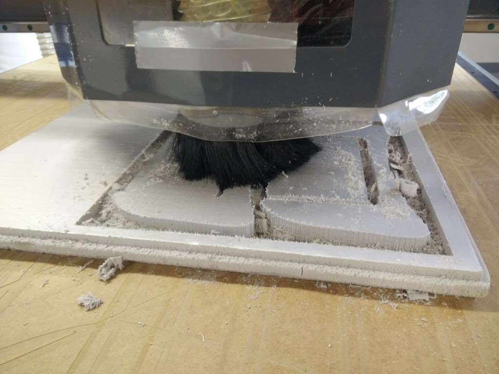

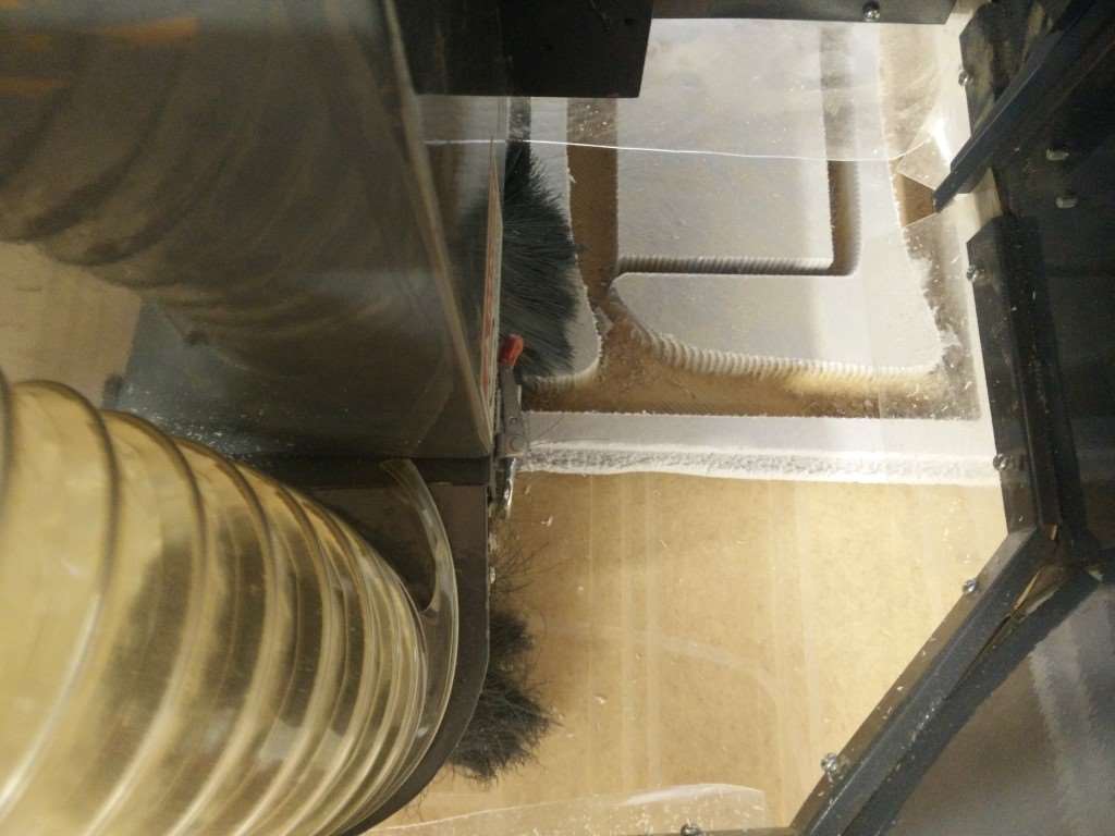

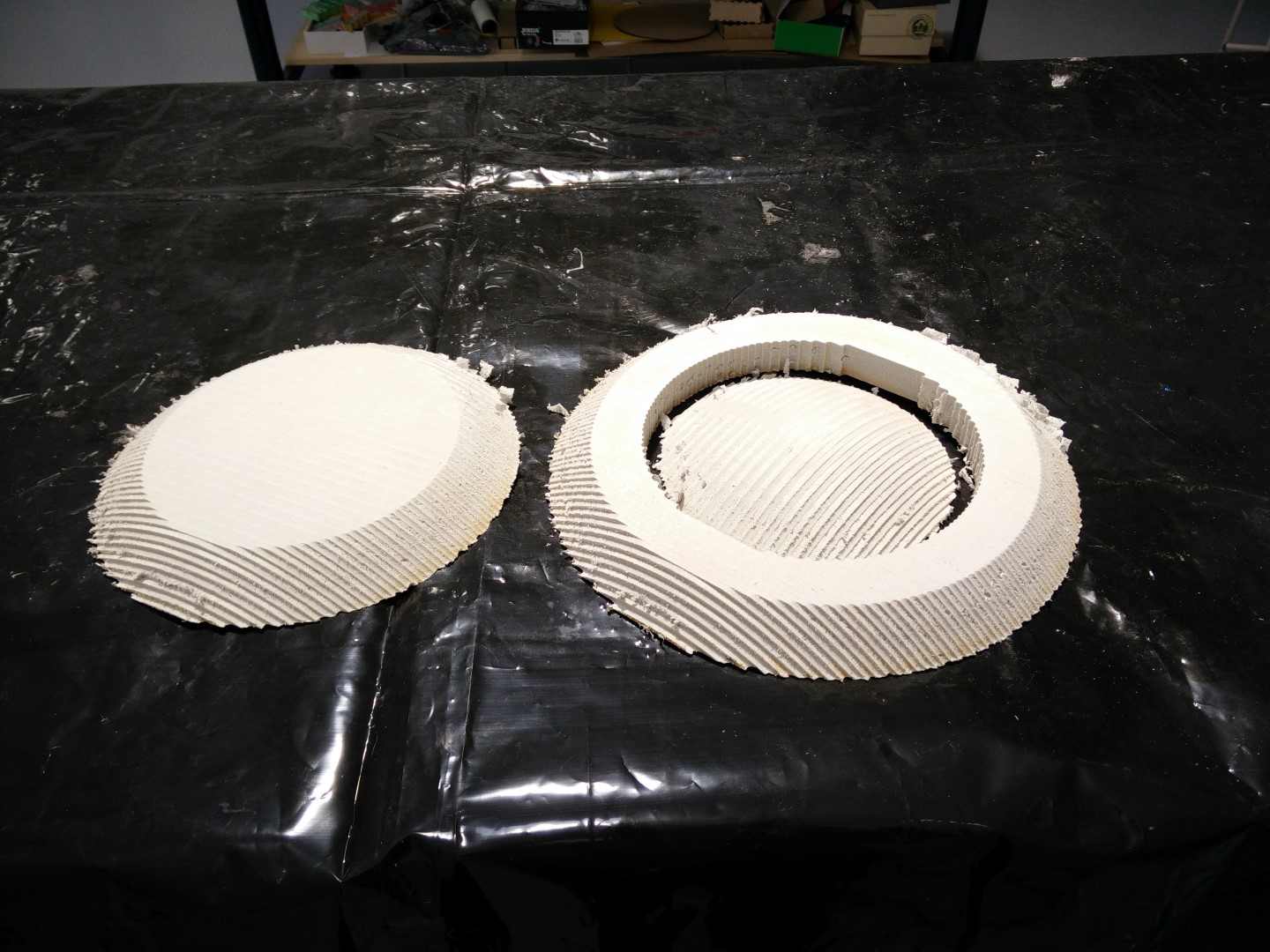
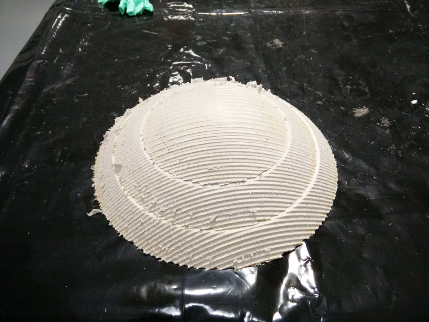
Ideally this mold should be millled as most 3D models, by having a roughing toolpath with an end bit and then a finishing toolpath with a spherical mill, but when I've checked the time to mill it, with a 15% overlap on the finishing, vCarved calculation was 3 to 4 hours for each pass, for a total of more than 10 hours of milling, and with limited time I had to cut down some finishing for later hand-processing. Parameters used for milling this molds were
Feeding speed: 2000 mm/minSpindle speed: 24000 rpm
Pass depth: 15mm for the 30mm boards and 20mm for the 40mm boards
The total time of milling was 1 hour 45 minutes, roughing was about 32 minutes and even when I run the finishing toolpath, I sanded it a bit, because I set a big overlap of 40%. The roughing and a bit of sanding would have been enough for the resolution that burlap can take.
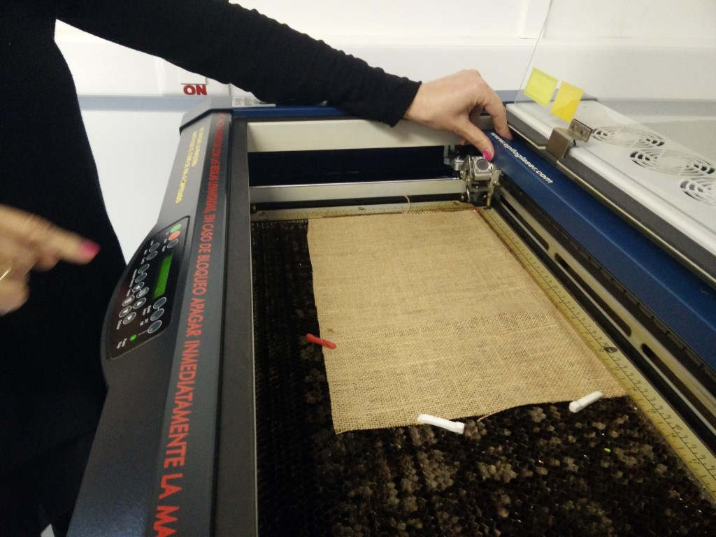
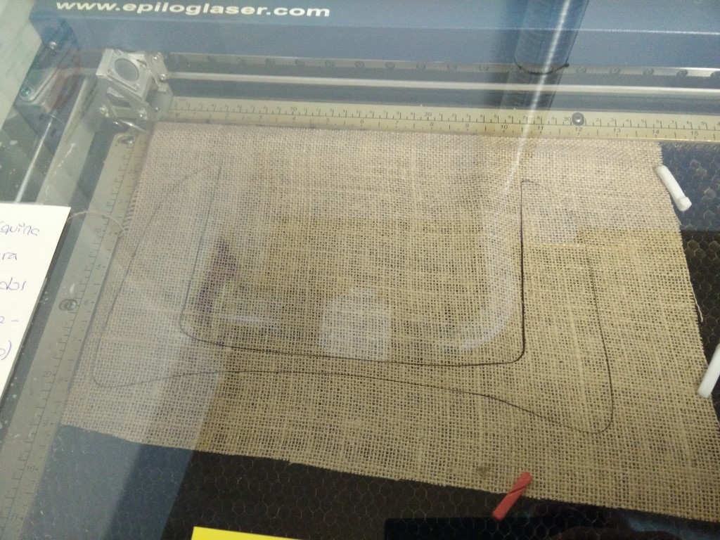
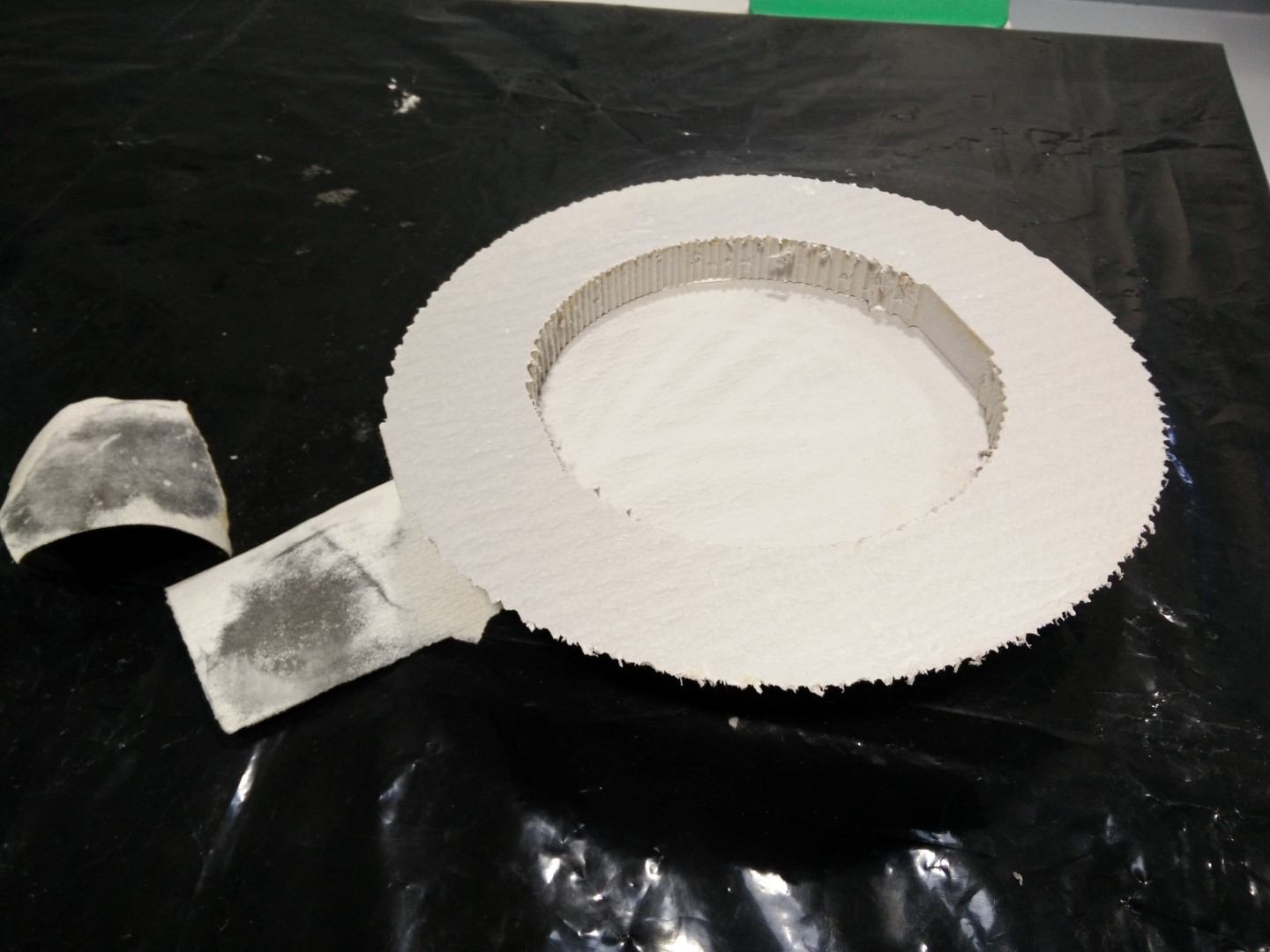
So while the machine was working I started taking the surfaces for the laser cutter from SolidWorks, for that I tried different combinations of flattened faces and offsetting them a bit so they would cover the whole shape. Burlap as other textiles cuts wonderful on the laser cutter, but for precise results, it would have been better to iron it to get it flat with no wrinkles. I have also cut some fiberglass for the landing gear, but this thin fiberglass (48g/m^2) doesn't keep shape when you handle it.


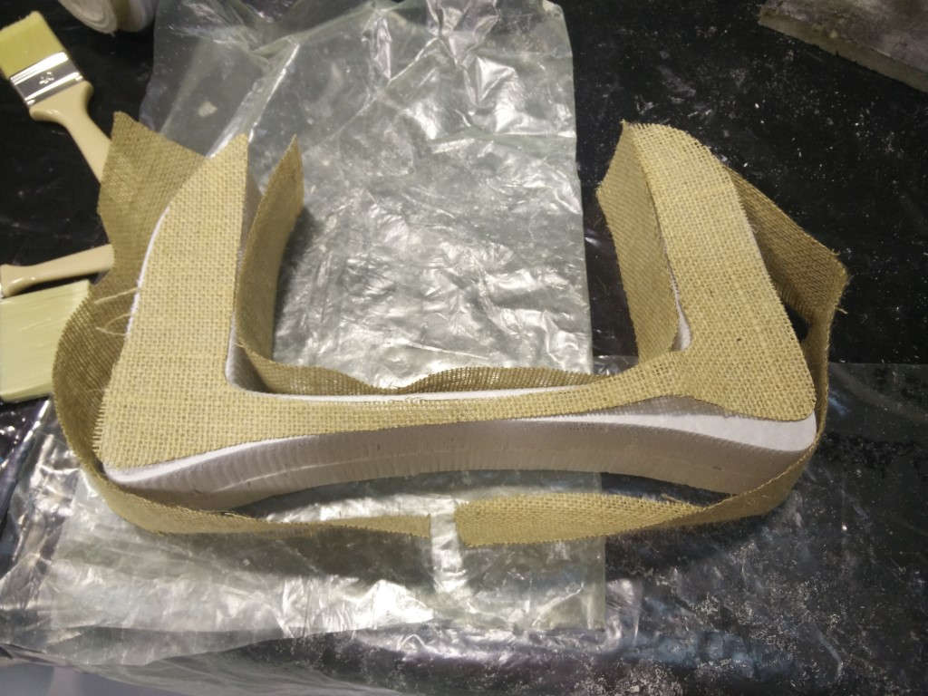
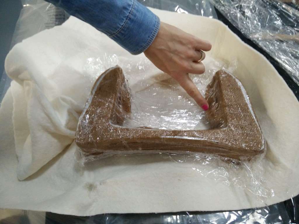
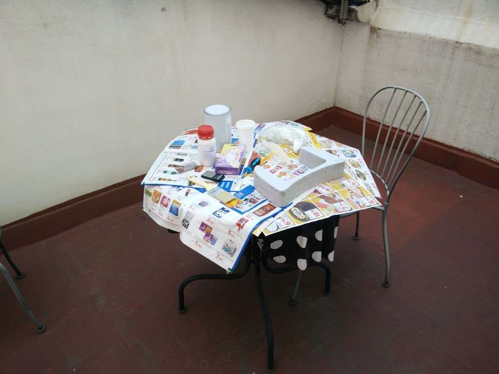
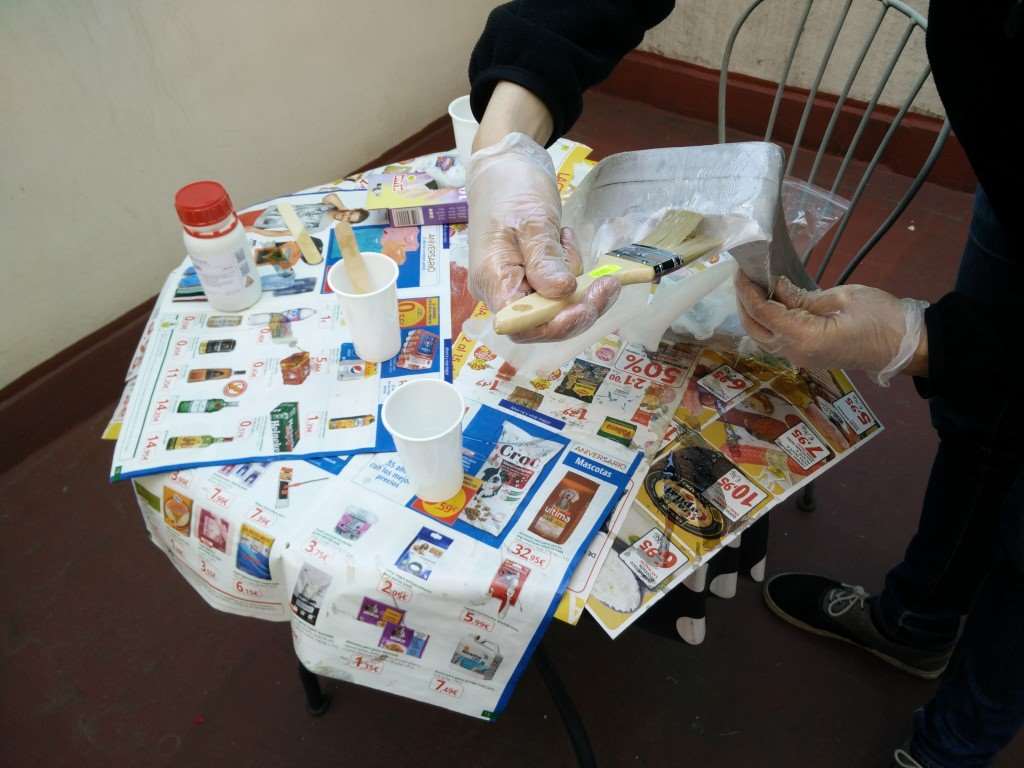
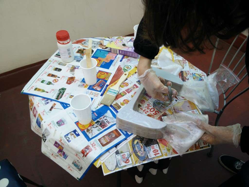
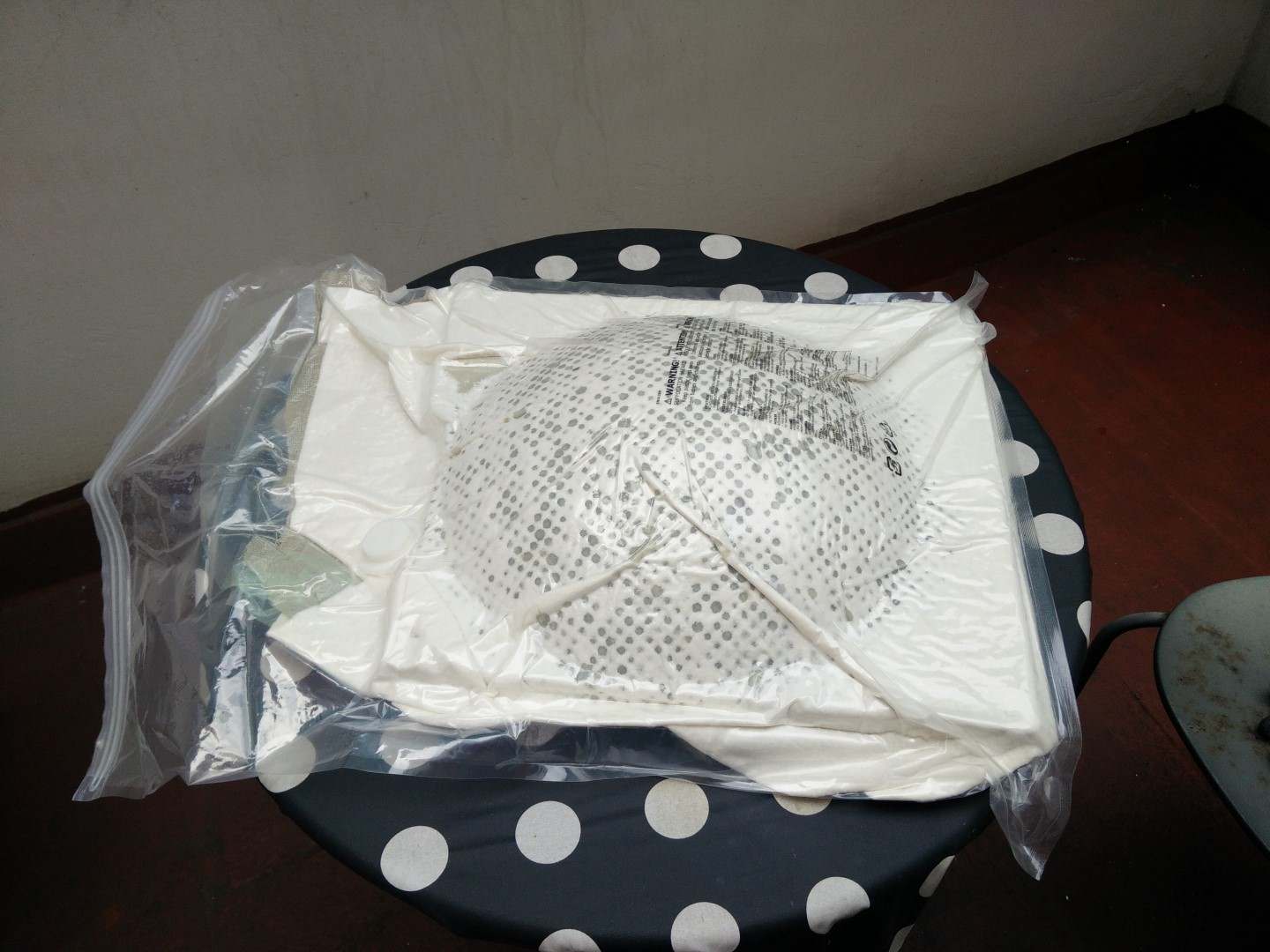
And it was time for the mixing and vacuuming process. I did this with Borja, and it was very helpful to have extra hands during the process. We poured 2 plastic cups with resin and 2 with hardener so we hade the proportion ready when needed, and stirring to get a uniform mixture didn't take too long. We started with Borja's mold. When I got to start with mine, the burlap didn't behave the same way as the thin fiberglass we used at fabLAB. So I tried to get it as uniform as possible even I asked Borja to cut some strips to "stitch" different parts. I was very unhappy with the result but I put it on the bag as carefully and possible and applied vacuum.
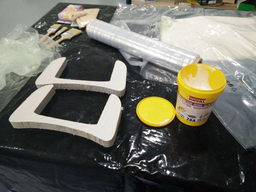
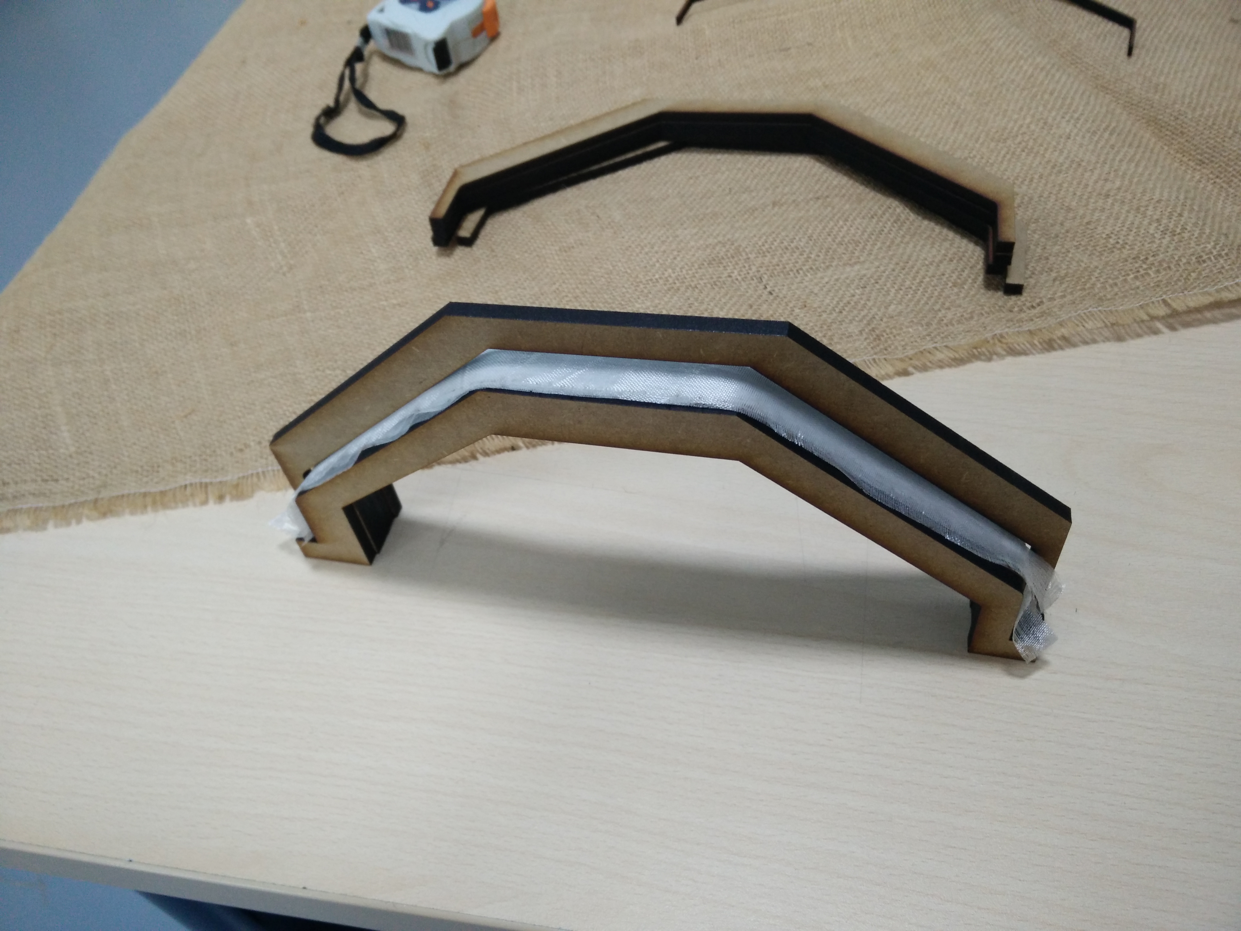
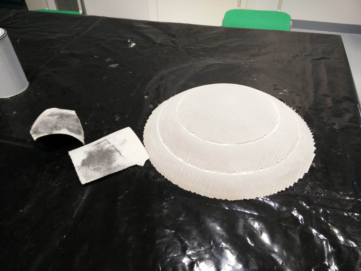
As for the landing gear, I tried to make a bit of an experiment and use MDF parts to make a shape of a mold, but it wasn't something very planned. And it didn't go well. I only have one picture of it before applying the epoxy. The 5mm MDF parts were glued together to make 2 parts for a mold, the idea was to cover it with plastic film and then put the fiberglass strips on it with epoxy and then use some rubber bands or zip ties to apply pressure. The general idea wasn't very good but what really failed is that I used too few layers of fiberglass, just 10, when it probably requires lots of them and bigger. Also, this fiberglass is 18g/m^2 which makes it very difficult to handle.
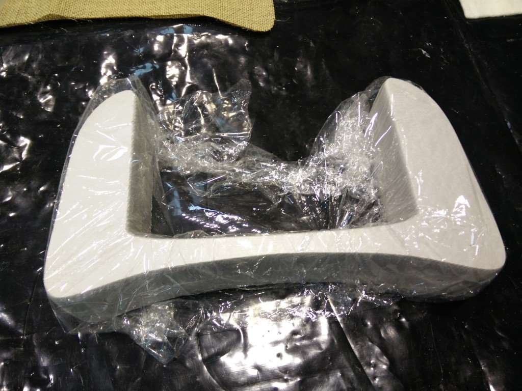
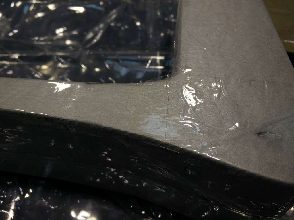
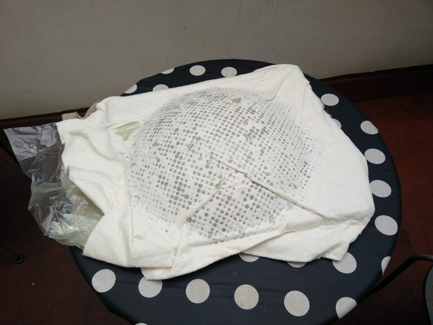
Next morning, when I arrived at the Fab Lab I was ready for the disaster, and it was. As seen in the photographs there were several reasons for it to fail. First, I think this shape is not good for this process, because of how steep walls are and the curvature of the shape itself, it's hard to get a good unfolding of the surface. Second, I the foam itself was not stiff enough to hold the vacuum pressure and bent a bit towards the inside, and also, at the bottom, the bag pushed up, so it would have been better if I glued a base to the foam, even just another layer of foam. I was a bit disappointed but I'm going back to León next week to make another composite with a more appropriate shape. On the other hand, I have some epoxy and fiberglass and I want to make the tray so I'm laminating it.


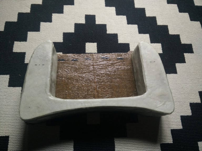
As I write this lines previous to the class, I have the polystyrene shape covered with fiberglass and epoxy drying, probably the best option for a shape like this. What I'm gonna do is to make the back part out of burlap, as it's flat, and I want to feel the stiffness of that composite. And in the end have my tray, that I won't probably use, but I want to make it!


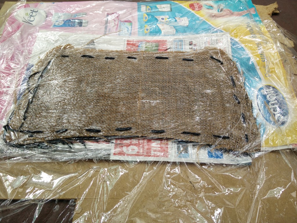
It is time to make some thick burlap composite, I'm using 4 layers of burlap to make the backplate of the tray for the RC transmitter. I cut them with the laser cutter then stitched them together to be sure that they keep in place. I'm also using weight for compression instead of the vaccum bag. I layered a film plastic, then the burlap and the epoxy and another film plastic so it doesn't stick. I'm using about 30Kg of weight. I'm also applying the epoxy to the four layers at once, from both sides, and squishing it trough the bottom layers.


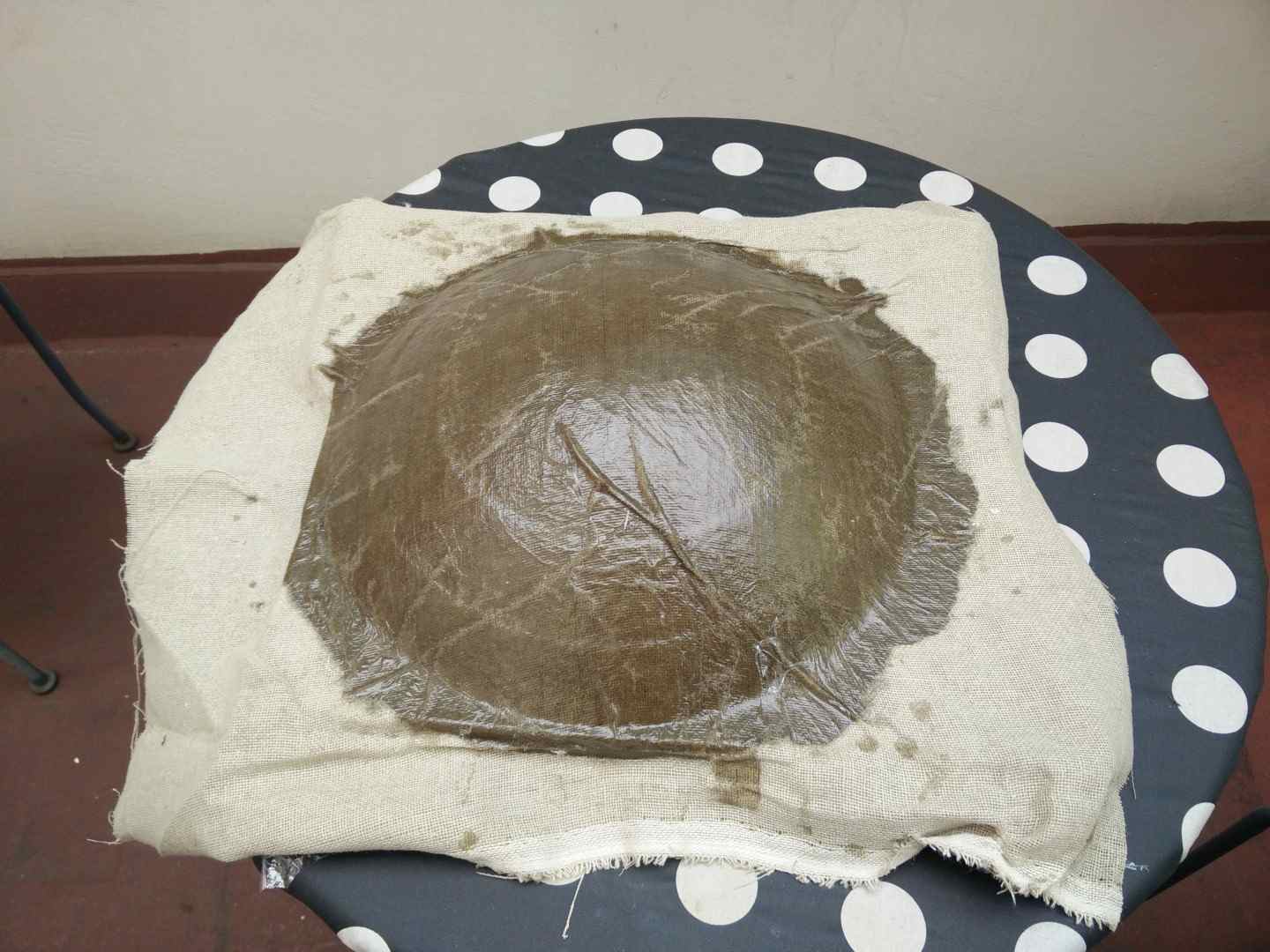
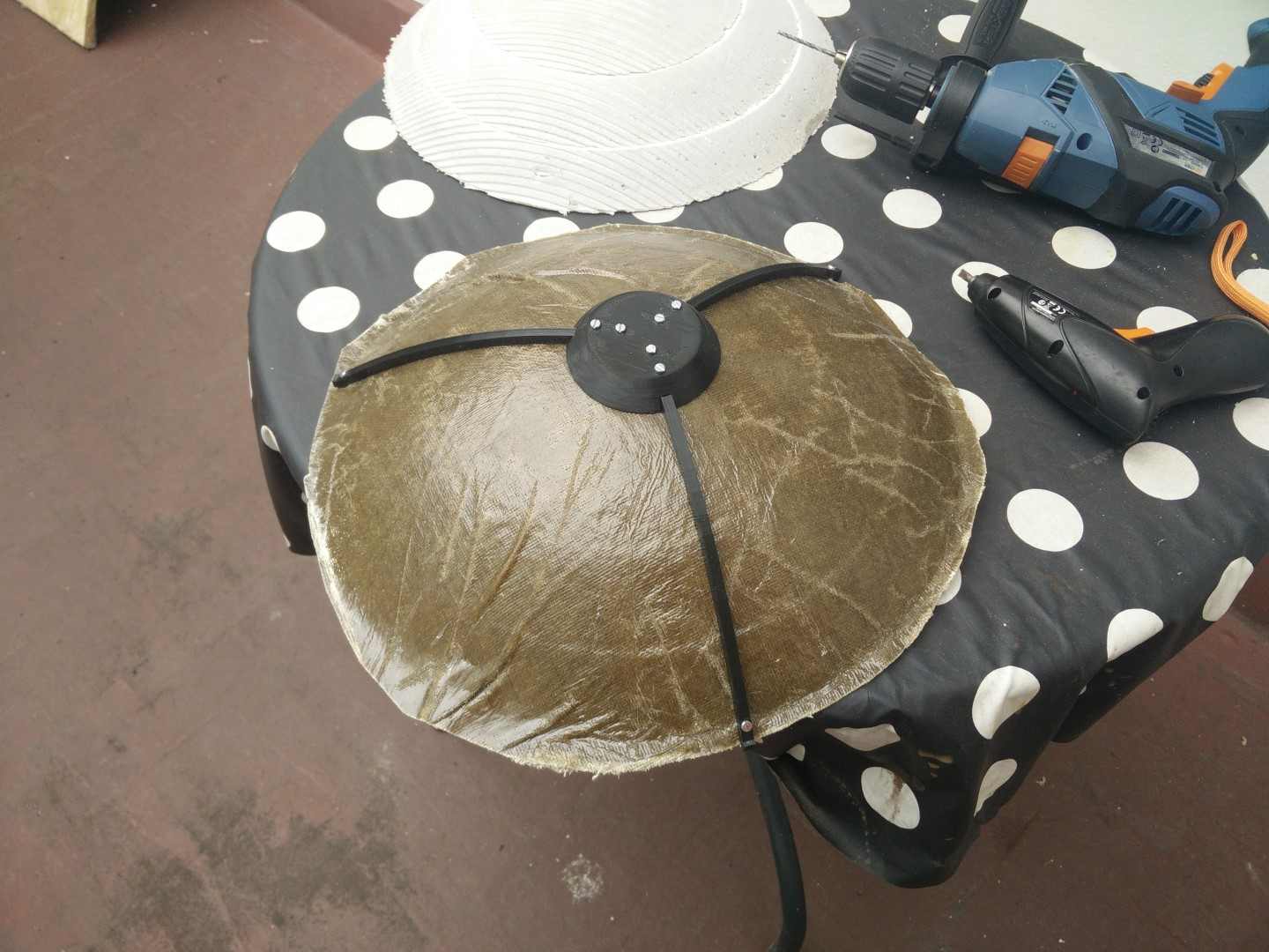
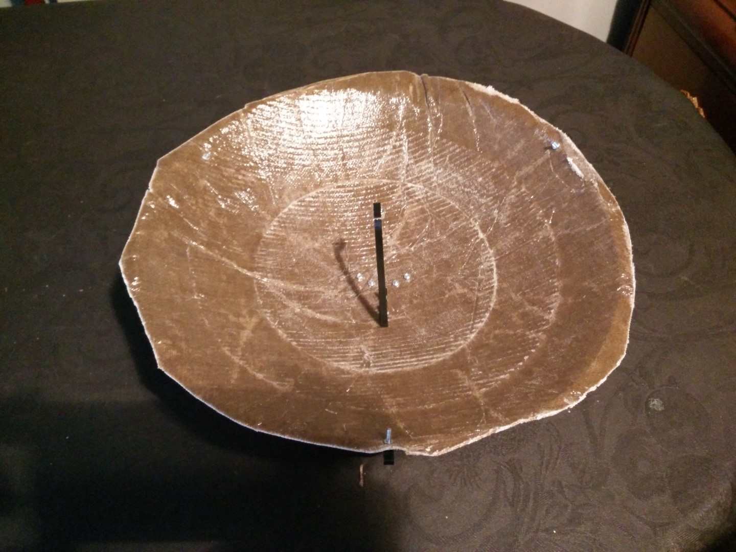
Update: I've been to León this Monday and tried something new with composites. Thinking about a non-steep surface I started thinking about parabolic reflectors and how useful it would be to make them for multiple projects. With a parabolic reflector, you get a solar oven if your rays are from the sun, or you can get a directional speaker or microphone if you use sound and depending if you place a microphone or a speaker on the focus of the parabola. And for antennas you would need it to be metallic, and that's where things will get interesting. First I want to test the process to get a parabolic reflector made of burlap, but I'm thinking about a couple of aluminum foil layers between burlap to get a metallic parabolic surface. But first things first.
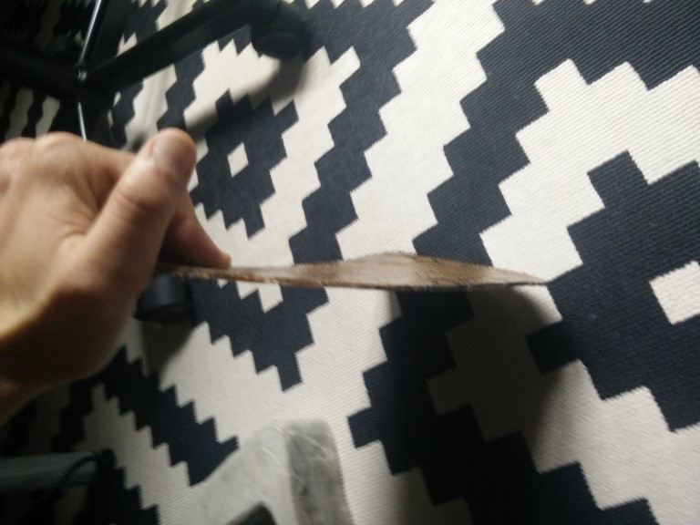
The parabola was more or less ok, a bit flimsy probably too big for just 3 layers of thin burlap. I'm working on a 3D printed structure to complement it and maybe turn it on my final project as a directional microphone. Also, I've made the back panel for the radio tray, using 4 layers of burlap and applying weight. That came up pretty nice, now I have to fix it to the foam part maybe with another 3D printed structure that serves also as part of the hanger.


This work it is continued in the final project
Machines and software used
SO: Windows 10SolidWorks
vCarve Pro
CNC TECCAM 500
6mm ball nose mill bit (2000mm/min, 24000rpm, 15 to 20mm cut depth depending on thickness)
Epilog Mini 24 (Burlap: speed 80, power 90, freq. 800 Fiberglass: speed 100, power 20, freq. 800)
Files
Landing gear mold using SolidWorks tools for molds (not fabricated) (.SLDPRT)
Landing gear mold for 2D laser cutting (.dxf)
Fiberglass shape for the gear mold (.dxf)
SolidWorks tray model (.SLDPRT)
SolidWorks 2-part mold for the tray (not fabricated)(.SLDPRT)
2D laser cut pattern for the tray (.dxf)
vCarve file example for the tray top part (.crv3d)
STL combining both slices of the tray (.STL)
First parabola mold (.SLDPRT)
Second part of the mold for the parabola (.SLDPRT)
STL of the 3 slices for 30mm thickness combined in one STL (.STL)
STLs of the slices for the second part of the mold, 4 independent files for 40mm thickness (.rar)