
15.Networking and communications
This week's assignment
- Design and build a wired &/or wireless network connecting at least two processors
- Software:
- -Eagle
- -Roland Vpanel
- -fab modules
- -Adobe photoshop
- -Arduino IDE
- Hardware:
- Roland SRM-20
- Soldering Iron
- AC adapter 12V/2A
- Materials:
- PCB (FR-1) x 1
- WROOM-02(ESP8266) x 1
- Capacitor 0.1uF x1, 10uF x1, 100uF x1
- Resistor 10k ohm x 6
- LED x 1
- Regulator 3.3V x 1
- Tact switch x 2
- Slide Switch x 1
- DC plug jack 5.5mm/2.1mm x 1
- 1x8 Pin Right Angle Male Header x 2
- 1x6 Pin Right Angle Male Header x 1
- Desoldering Braid x 1
- Solder x 1
- Flux
- Ethanol
- Cotton bud
- Double-sided tape
- Mitsuwa Paper Cement Solvent
- Aluminum foil
- Alligator clip with wire
- Files: Schematics(eagle)/ Board(eagle)/ Circuit(PNG)/ Hole(PNG)/ Outline(PNG)/
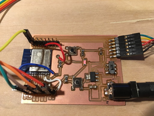
I need to connect internet in my final project. So this week I use ESP8266(WROOM-02 in Japan) to make wifi circuit board.
Procedures:
Unfortunaltely I couldn't success in a week.
After some experiments, It seemed problem was electicty was not enough as I used USB power from PC.
So I added DC jack and provide power from AC adapter. And also another problem was there need some pull up
resistor and switch to change ESP8266's mode. So I refered ESP8266's data sheet and switched programming mode correctly.
For more detail please kindly refer Final project page.
Finally succeed to connect Internet.
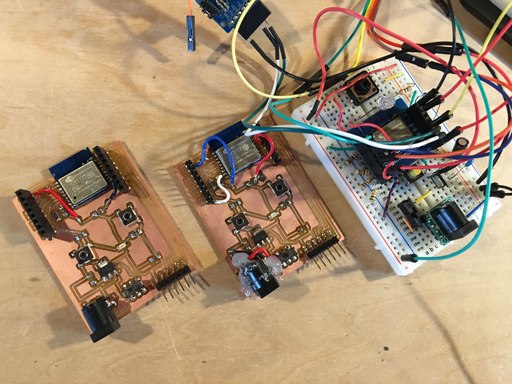
Used bread board to try and error before making final board.

To change mode, need to follow datasheet's instruction.
