Electric Production
◆ Making milling data
Download and edit png files.
We(from FablabKamakura) decided to make hello.ISP with resonator.First, download traces and interior png files from Class page.
I add my name to original data with Illustrator.
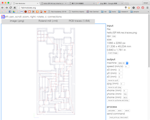
Process files in Fabmodules.
Fabmodules is browser based wide-use CAM for digital fabrication machines.This time I make .rml(Roland Mill) file from .png for SRM-20.
- input format. → image(.png)
- select png file in your PC.
- output format. → Roland mill(.rml) traces → PCB traces(1/64)
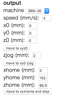
- choose your machine → SRM-20
- set x0,y0,z0 = 0.
- change other properties. ※traces → cut depth = 0.2
- click [calculate] button.
- check the path and save it.
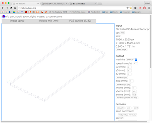
interior → PCB outline(1/32)
◆ Let's mill it with SRM-20!
- stick copper board on waste board on base panel.
- set base panel in SRM-20 main body.
- set 1/64 bit with hex wrench.
- connect SRM-20 to PC, and open software(V-panel for SRM-20).
- move head and set current XY position as XY origin.
- with holding mill, loosen fixing screw. then, hit the tip of mill against copper board softly.
- set current Z position as Z origin.
- load .rml file and run.
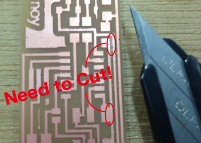
◆ My mistake
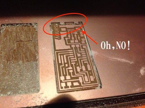
Outside path doesn't match. I don't know why, so I check .rml files.
How to read .rml file
I search and find some references.According to this page...
- PA - Pen Absolute
- VS - Velocity Select
- VZ - Velocity Select for Z-axis
- MC - Motor Control / 0-OFF, 1-ON
- PZ - set Z origin
- PU - Pen Up
- PD - Pen Down
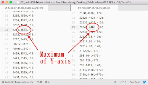
Finally, I found the maximum value of Y-axis is strange.
Inner maximum is larger than outside of it!
So I think I mistook at setting origin.
Resolution issue
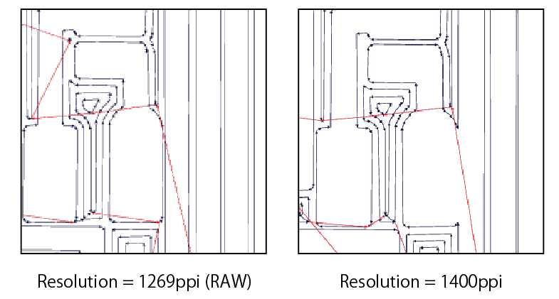
I made another data and run, then I found resolution is so important.
Different resolution makes defferent path, although other properties are same.
I made path file with not original resolution, and got some problem on board.
If you want to edit existing .png file, you have to set same resolution.
◆ Soldering
- ATtiny44A
- 20MHz resonator
- 1μF capacitor
- 3.3V zener diord
Diodes have "Cathod band" that tell you which side is cathod. - mini USB port
- pin head
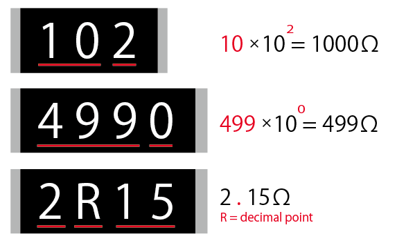
- chip resistor
You can know the value by checking number.
Soldering is from inside to outside!
◆ Programming
It needs long process..Make ribbon cable
Through 6 cables to connector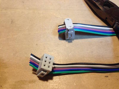
Program firmware
I read FabAcademy's tutorial page.(walkthrough via Arduino UNO)※Before start, you need to download Crosspack AVR X code fab_ISP_mac_0.8.2
- unzip firmware, and go that directory via terminal.
- type "make clean"
→ Error "Agreeing to the Xcode/iOS license requires admin privileges, please re-run as root via sudo."
→ I need to open X code, and agree terms(http://qiita.com/kazoo04/items/880283612abd85c0610a) - type "make fuse"
→ Error "avrdude: Error: Could not find USBtiny device (0x1781/0xc9f)".
→ I need to connect device.(=Arduino UNO) - Open "Arduino ISP" program from Sketch examples.
- Connect Arduino and FabISP via ribbon cable.
- Slave Reset(RST) - pin10
- MOSI - pin11
- MISO - pin12
- SCK - pin13
- V - 5V , GND - GND
- upload ISP program for Arduino
→avrdude: Error: Could not find USBtiny device (0x1781/0xc9f)
→ need to fix makefile configuration for avrdude
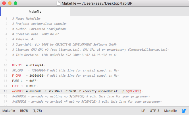
Comment out exisiting #AVRDUDE lines,and write following one.
"AVRDUDE = avrdude -c stk500v1 -b19200 -P /dev/tty.usbmodem1411 -p $(DEVICE)"" - type "make fuse" again.
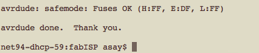
Finish
Get rid of 0 ohrm resiters, that'all!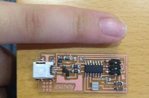
Extra Error
In week8, I want to use FabISP as a programmer, but a problem happened.If success, we can see FabISP in Mac System profiler > Hardware > USB > Hub.
But first time I cannnot find it.
I search for the way to solve and find Shino Onodela's page.
She wrote "Open terminal and type "system_profiler SPUSBDataType" .
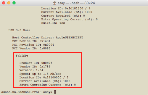
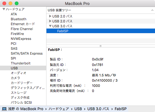
After that, I can find it! yahoo!
◆ Data
trace png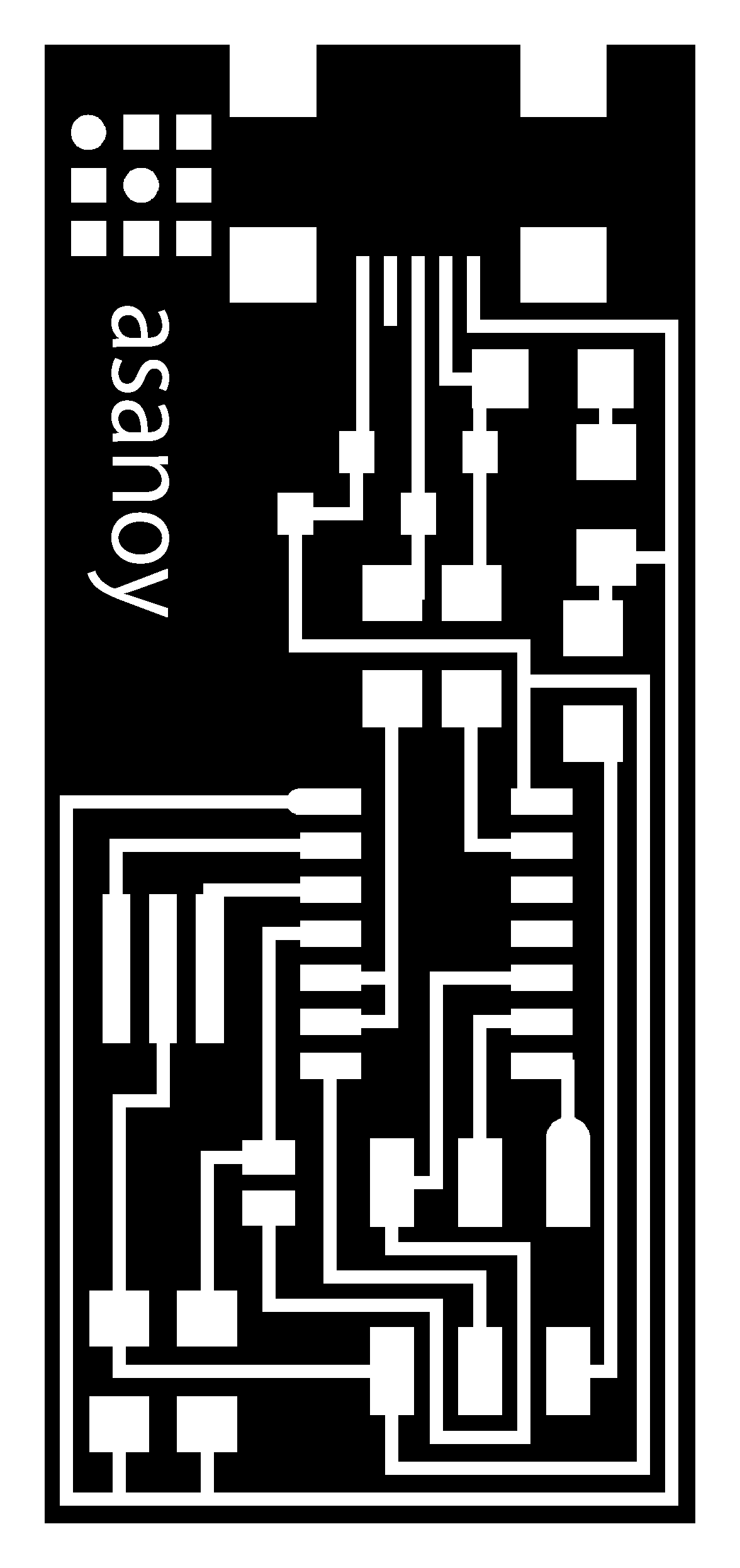
trace rml
interior rml