Final Project: Development Plan
Final Project: Process
Final Project: Process
I missed 6 weeks of Fab Academy due to my other PhD research commitments, which basically means I have shit loads of work to do now and I need to do it smart and time efficent. We´ll see how far I get.
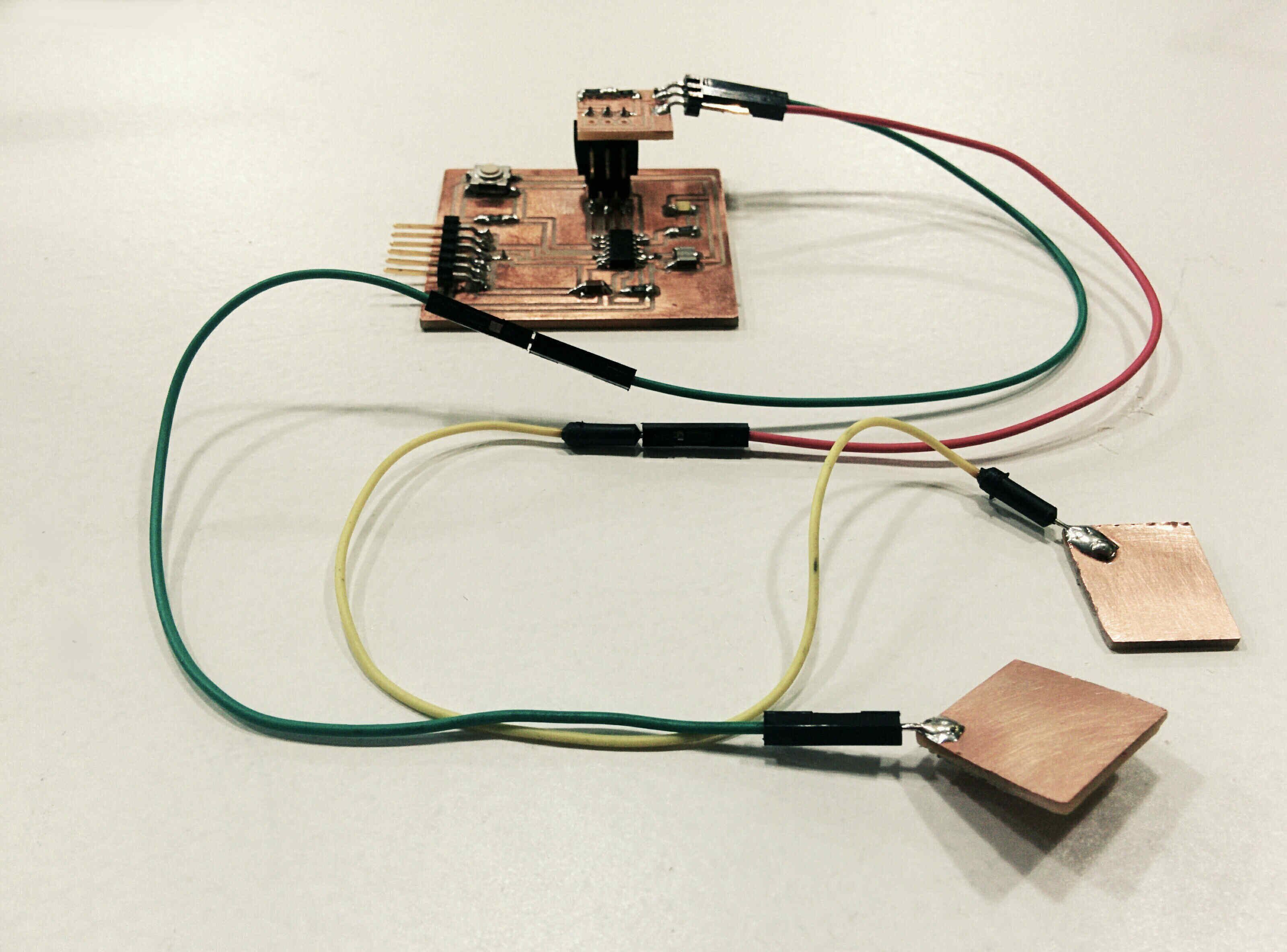
Hardware/Software Communication
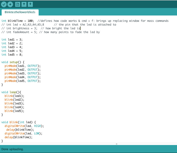
Hello World as Prototype
First is the making of a prototype, which will tick the boxes of week 11 and week 13 assignment. Next, I have to combine the two codes I previously made. I have two codes working in Arduino: one detects the sensor input and visualises the reading in a processing graph. The second code blinks five LEDs on my helloworld board up and down. Now I try to combine them: if the sensor value is low, only one LED is on. With increasing sensor intensity more and more LEDs shoud turn on.
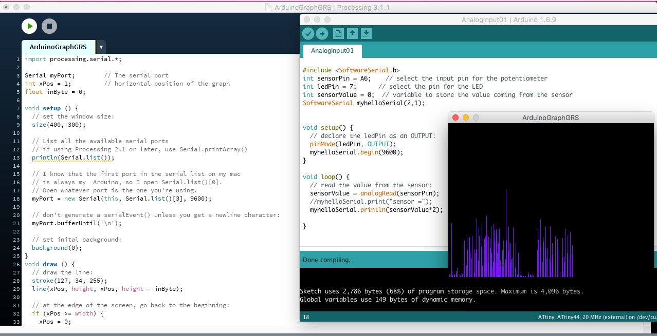
Experimenting with Code
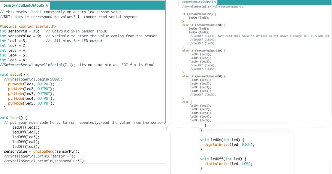
1) Instead of the whished for result one or two LEDs are on continously, if I activate the sensor one LED turns on (if I only define one), if I try it with all 5 there is no sensor reaction and the LEDs glow weakly.
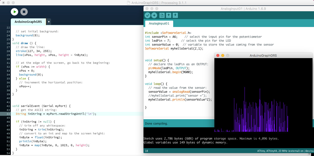
2)Next: code for four leds works more or less: leds are now off at the beginning, and turn on with sensor input. BUT: all LEDs are blinking instead of steady glow; all LEDs are on together, there seems to be no difference according to sensor value; all LEds glow rather weakly.
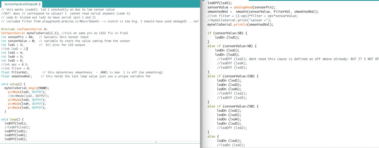
3)Next: seems to be working, LEDs blink 1-5 according to sensor value
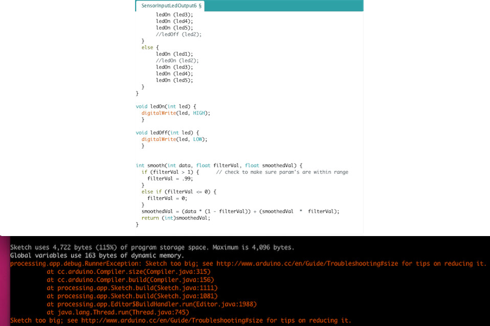
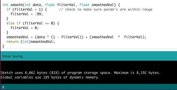
4)Now I want to smooth the sensor signal with the help of this tutorial. After including the relevant code line I compiled - and I am out of space on my ATTiny 44 : (
Okay, Back to Hardware
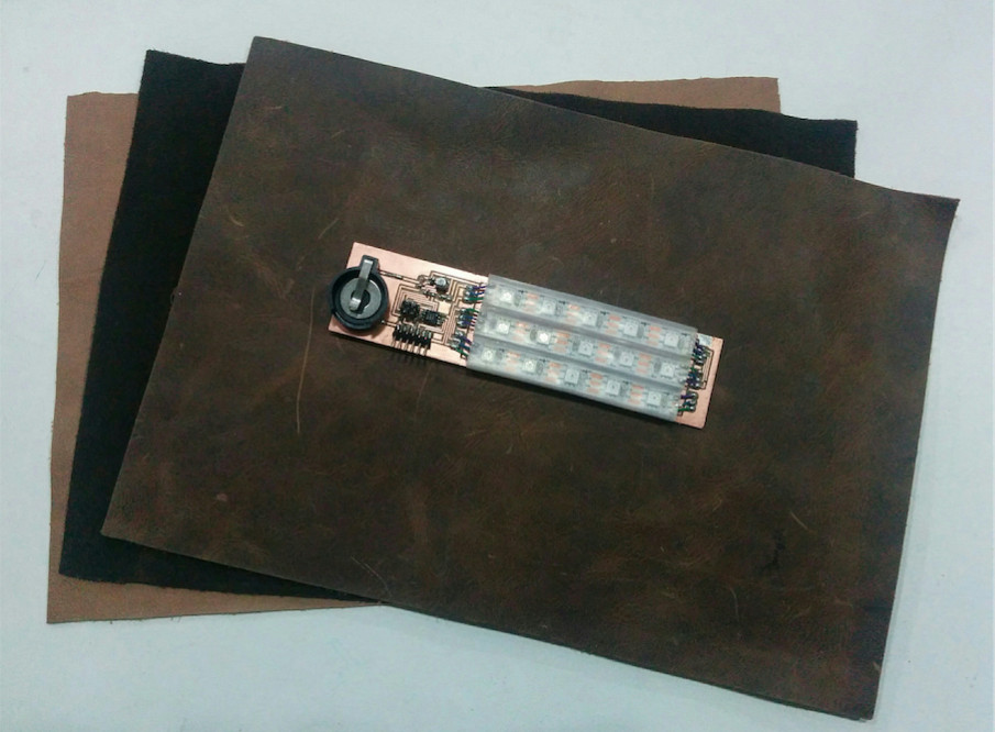
I test now if I can place the sensors top and buttom on my arm and still get useful results (=YES), sensor placement determines my board design. Which will be the next step: redesigning the helloworld board, kicking off some un-needed components (chrystal, button) but replacing the ATTiny 44 with the ATTiny 84. I also will replace the 5 LEDS with 15 RGB Leds.
.No ATtiny84 left in the Lab. So I have the choice between ATMega32 or ATTiny85. The Mega is a bit overkill for my purpose, I don´t need xx pins or 32KB flash memory. However, my final project for FabAcademy should be a proper protype for a device that needs to perform properly during the MAchine To Be Another project. The Mega gives me the possibilities to adjust, build up etc. The ATtiny 85 seems a better fit with 8 KiB Flash memory and only 6 pins. I would use only RX and TX for computer communication, one pin for 15 pixel RGB LEDs and one pin for the sensor. I tried a trick: I ran my too-big-for-AtTiny44 code in Arduino again, but changed the processor settings under the tool menu to ATTiny85. The ketch uses 4,634 bytes (56%) of program storage space. Maximum is 8,192 bytes. So I have some margin, but worry that the programing of 15 LEDs might take up too much space. I will use the PixelRGB LEDs, they go on one pin, but still need to loop through each. Another contra for the ATTiny85 is the experience of another FabAcademy student, who also wants to blink PixelRGB LEDs in a pattern, according to sound input. He tries to code the ATTiny85 and there are connection problems. Seems like AtTIny85 is usually coded in C not in the Arduino. Hmpf, I want the ATTiny 84!
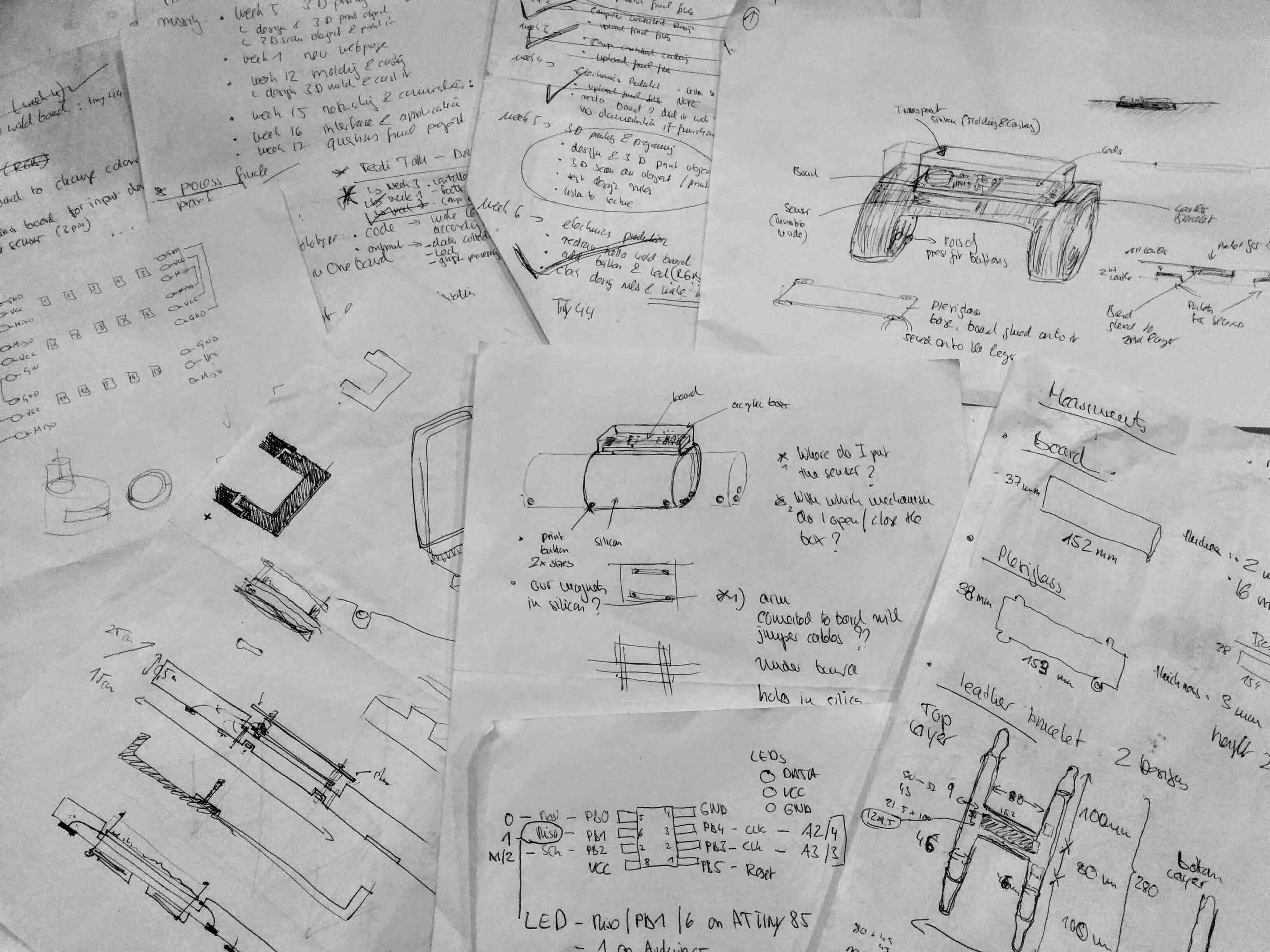
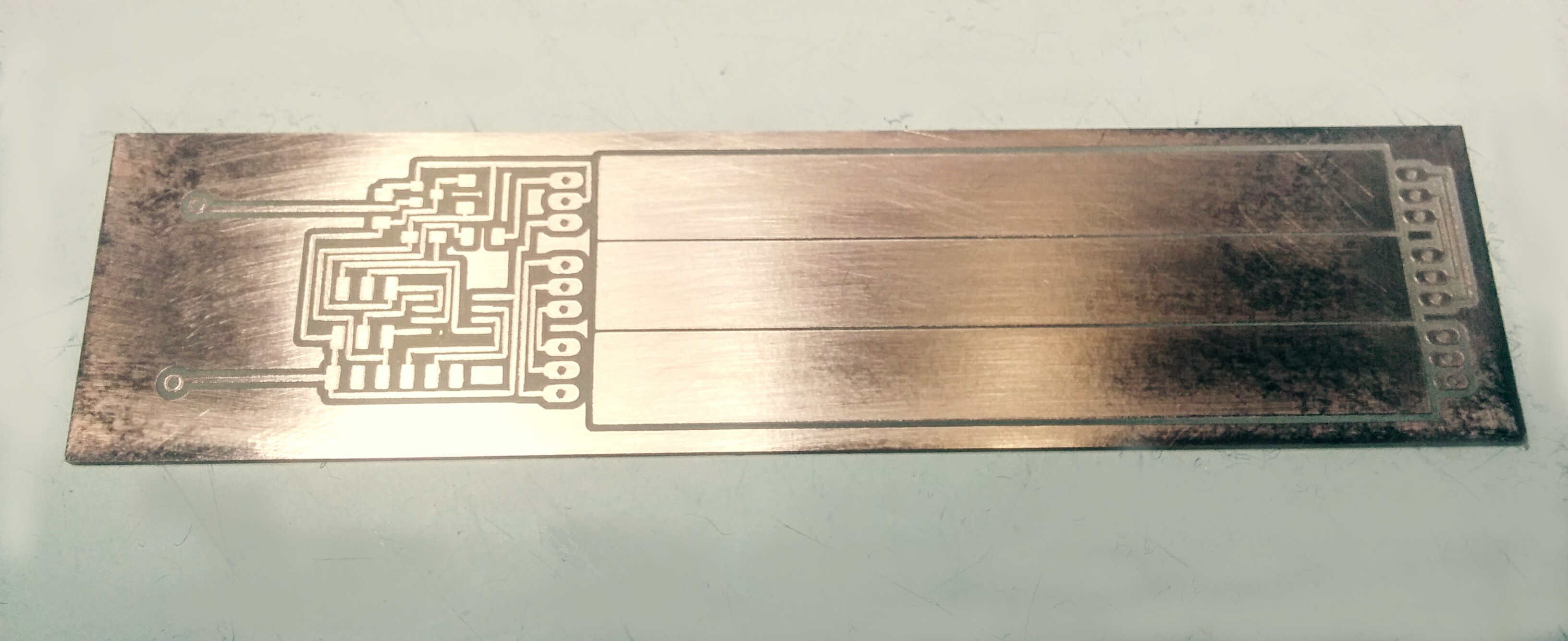
Final Sense Board Design
Somehow I am doing all at once, moving back and forth between hardware, code and design. All determine each other, so I guess it makes...sense.
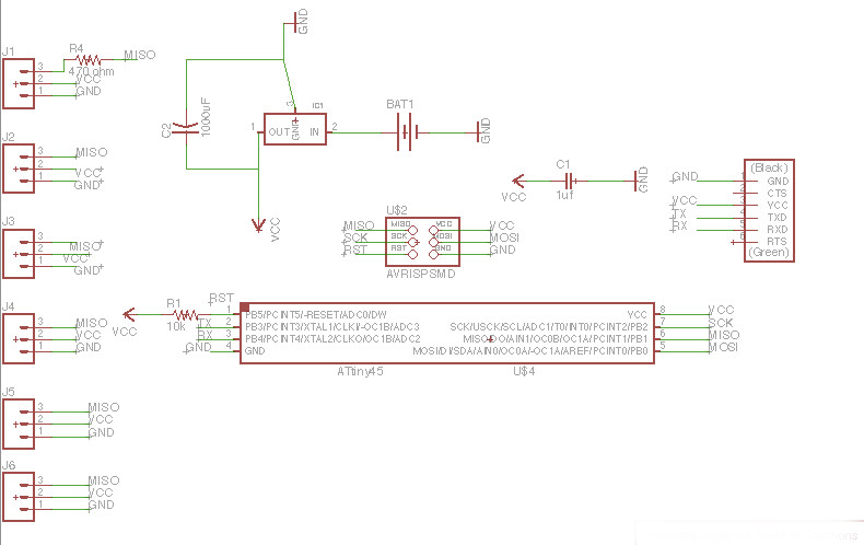
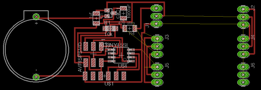
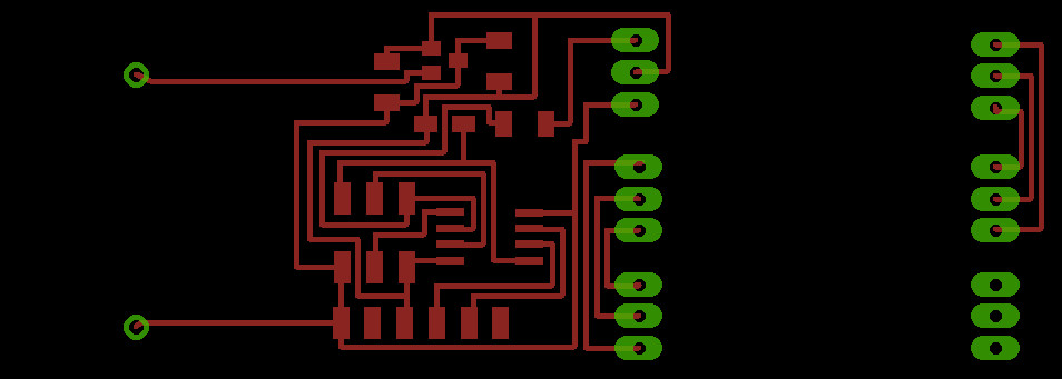
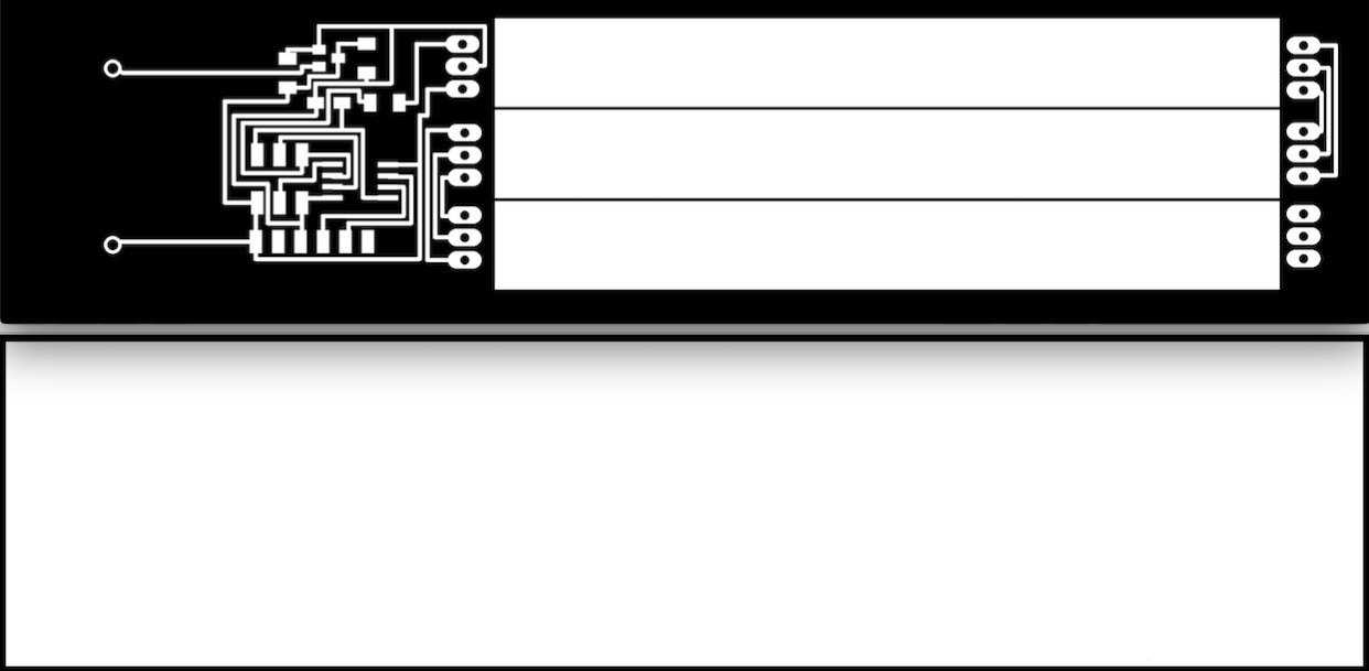
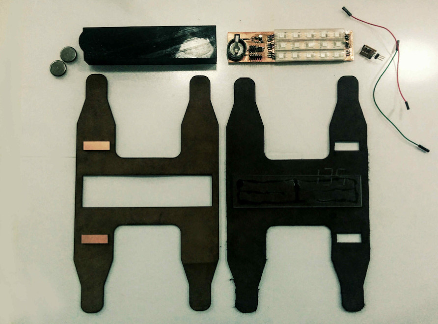
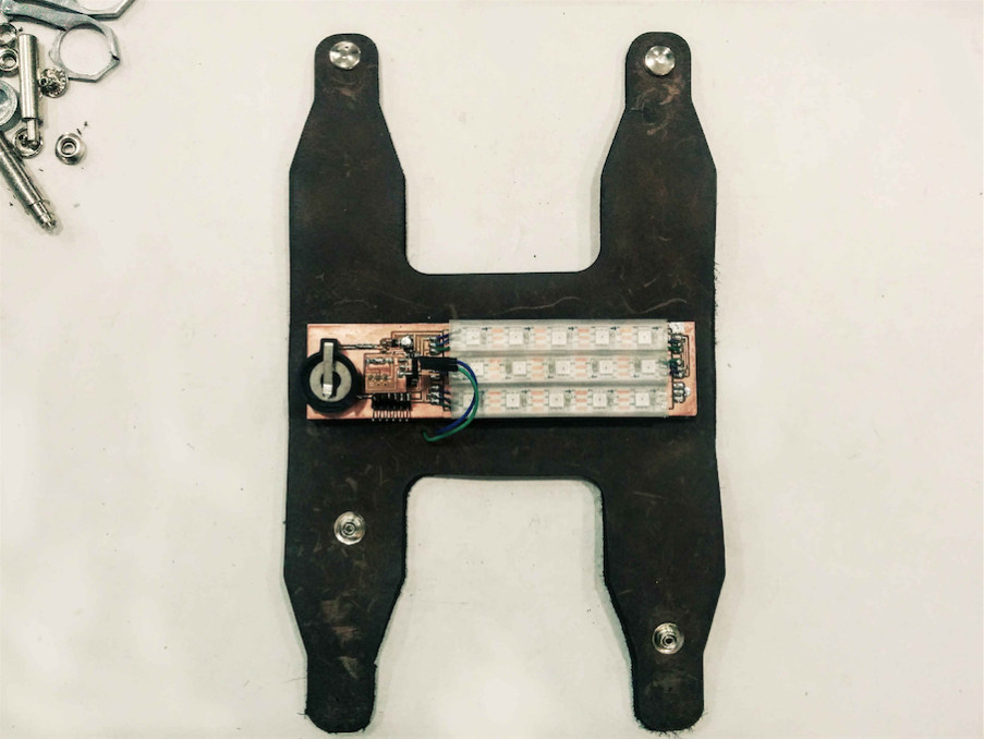
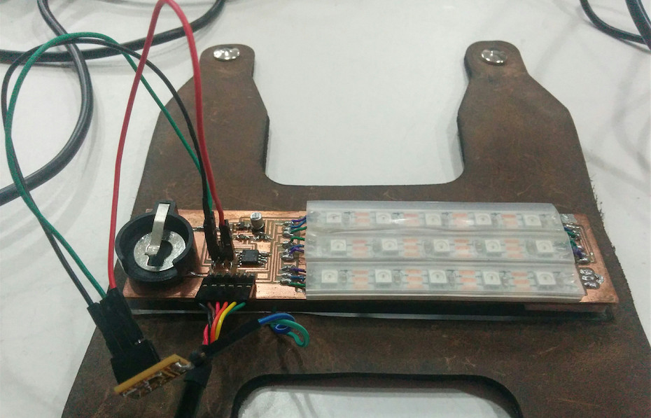
I now design my "final sense" PCB, inlcuding 15 Pixel RGB LEDS from Adafruit, here is the guide. My board wil be very long, fitting on the lower arm. Here is the schemantic and trace design, a useful tipp: To open two Eagle projects: type into terminal "open -n -a EAGLE"
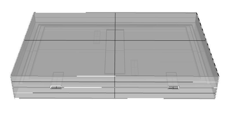
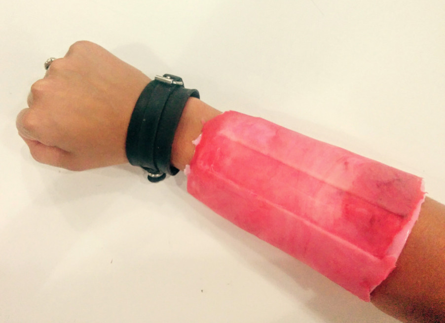
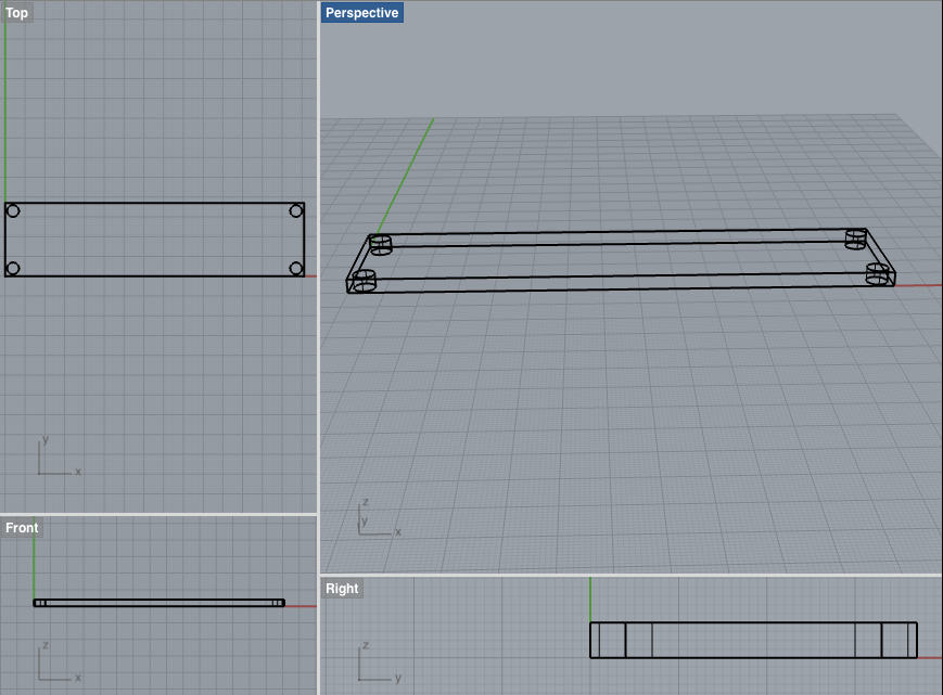
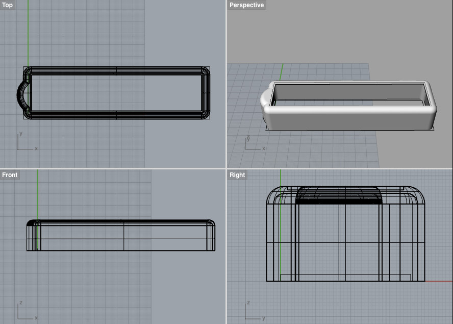
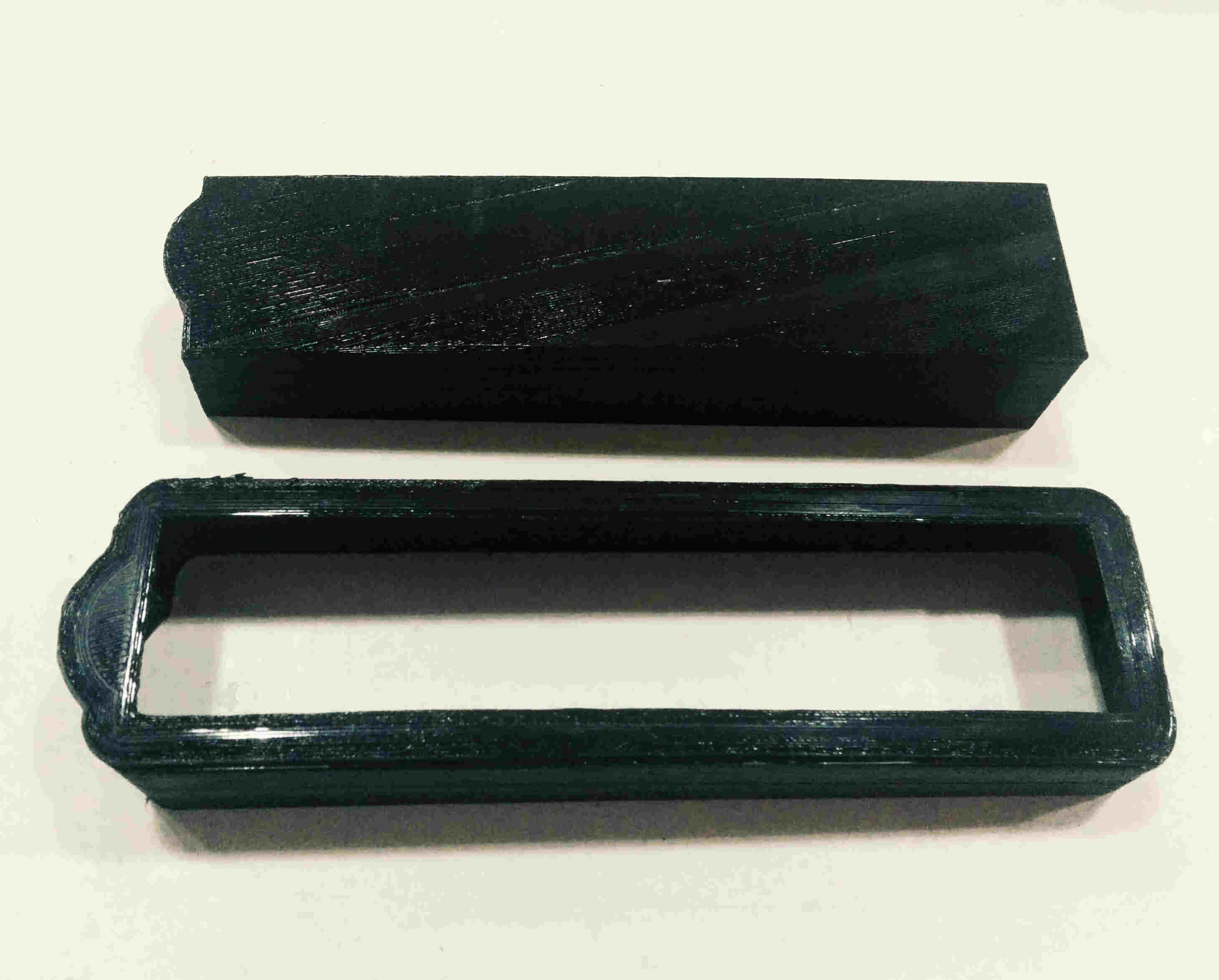
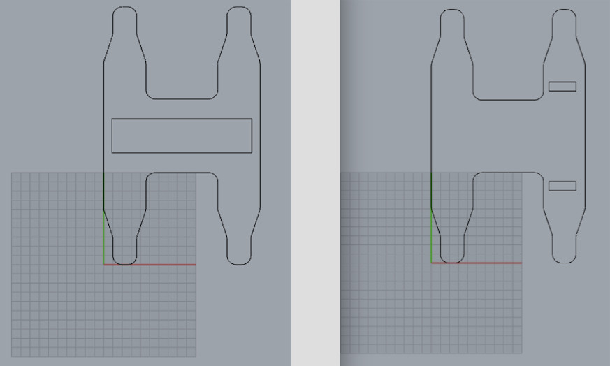
Bracelet Design
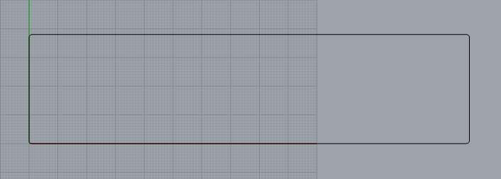
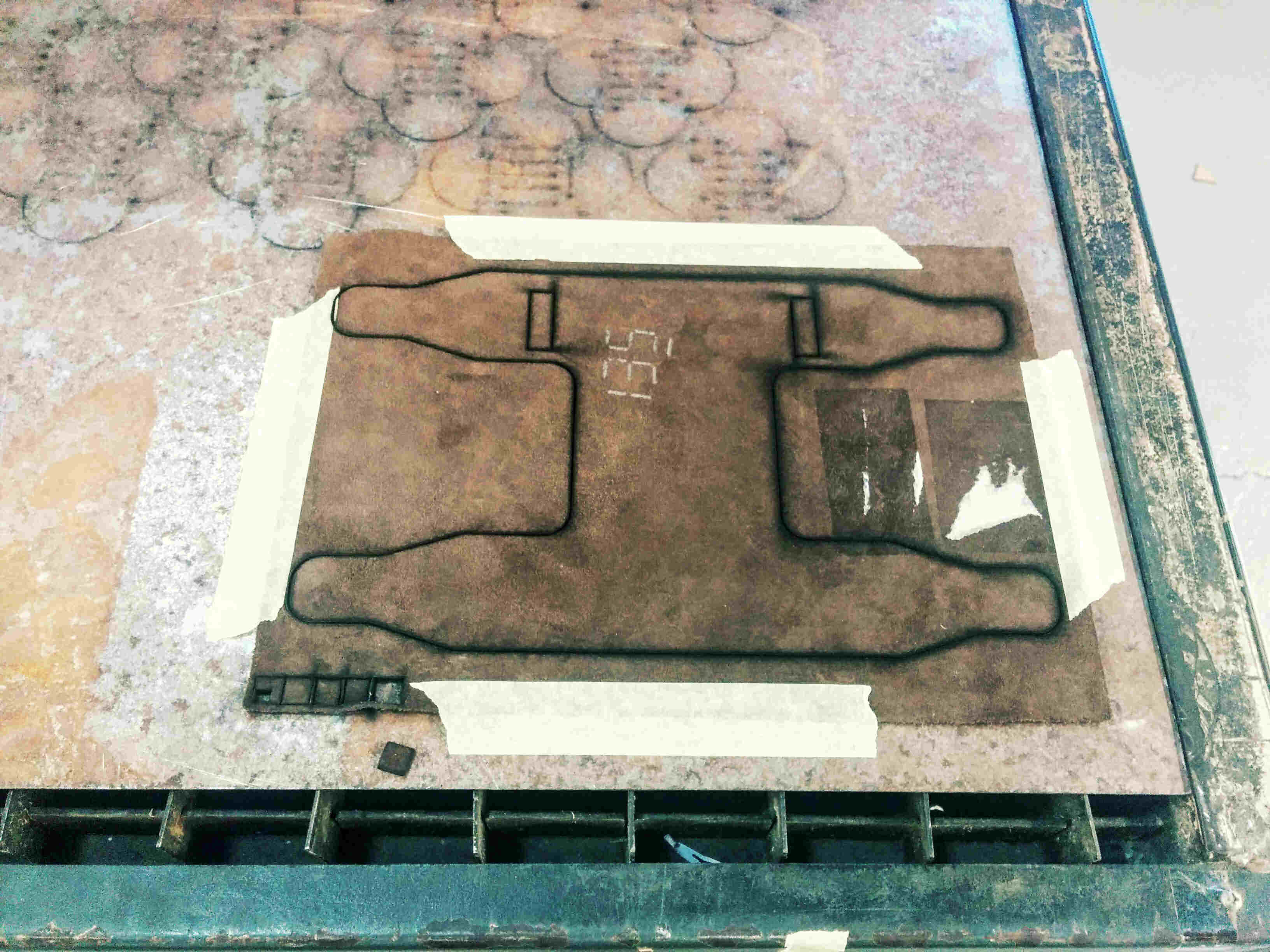
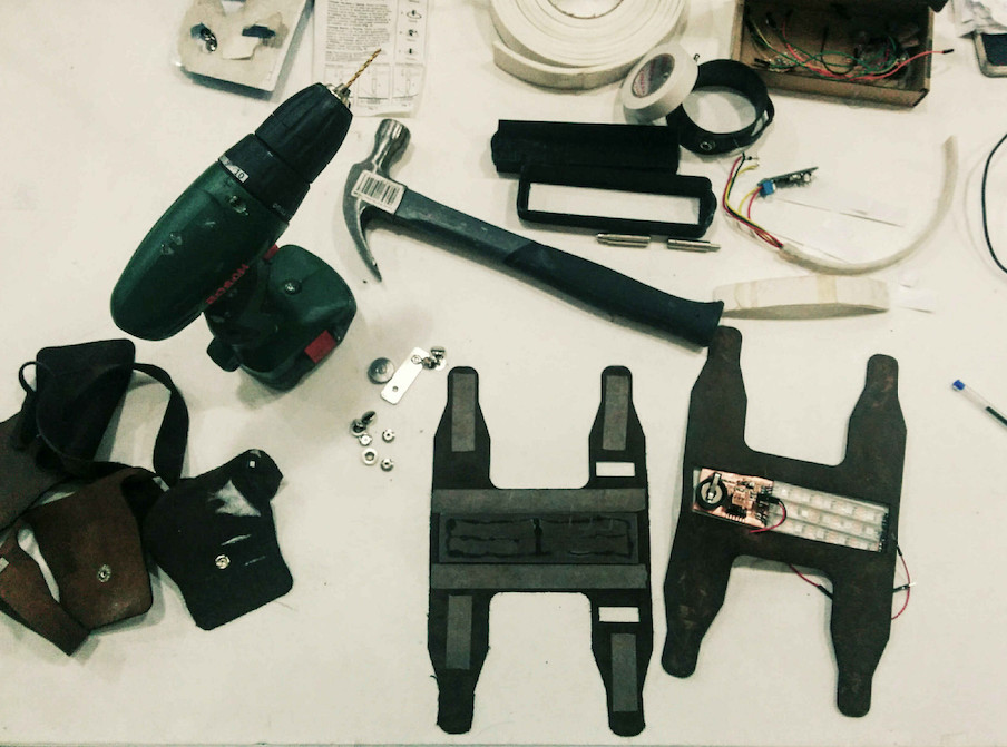
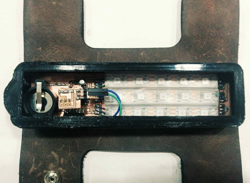
Intensity is on the rise. I need to do two things: soldering three more parts on my PCB and generating the GCode for milling the casting form for my silicon bracelet prototype (see week 12). Well, all two (...) soldering irons are in use (the third one broke) and apparently students get into conflict mode over the big milling machine already. I better cut my Rhino model in two parts and mill the form on the Roland.
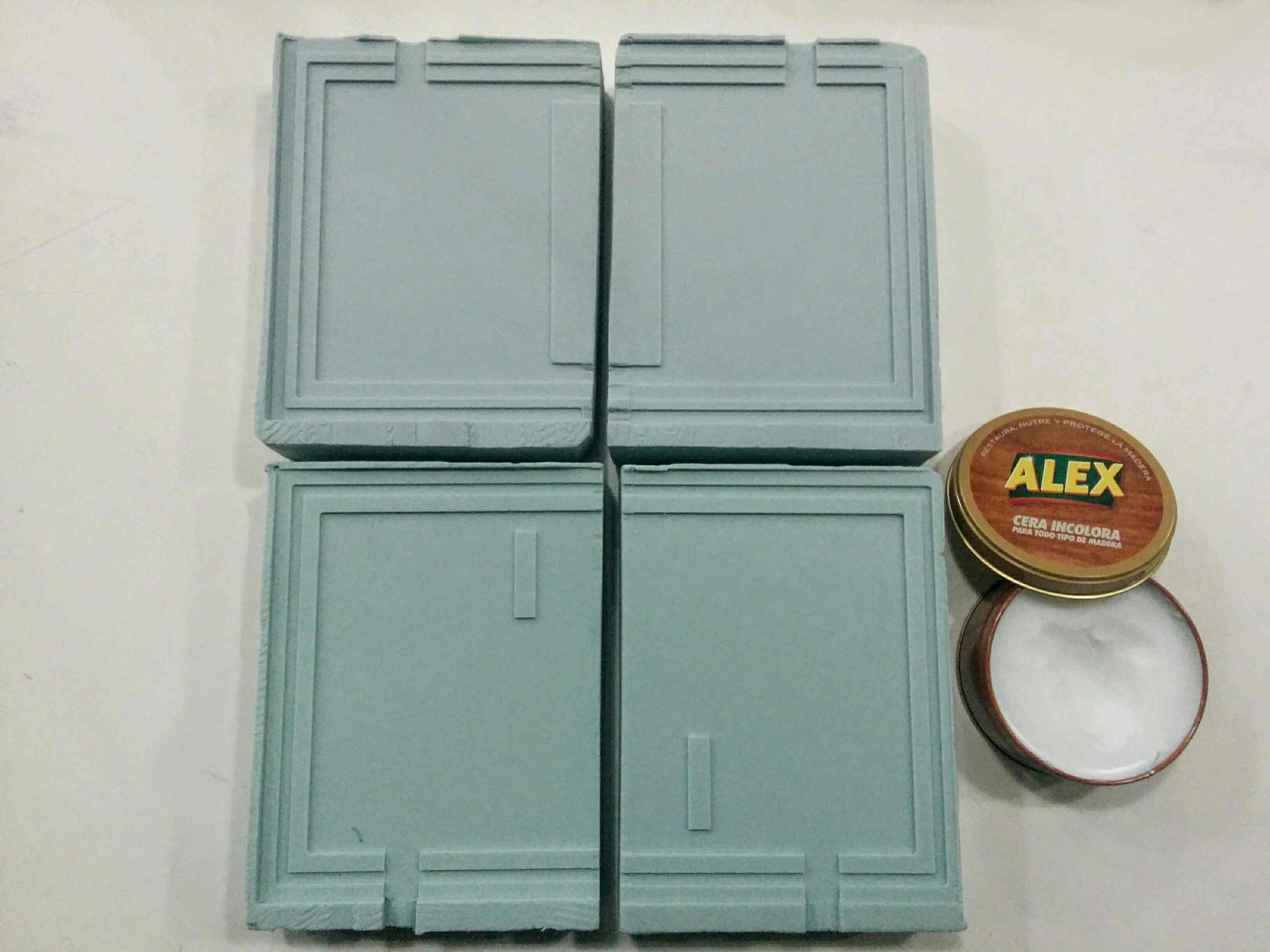
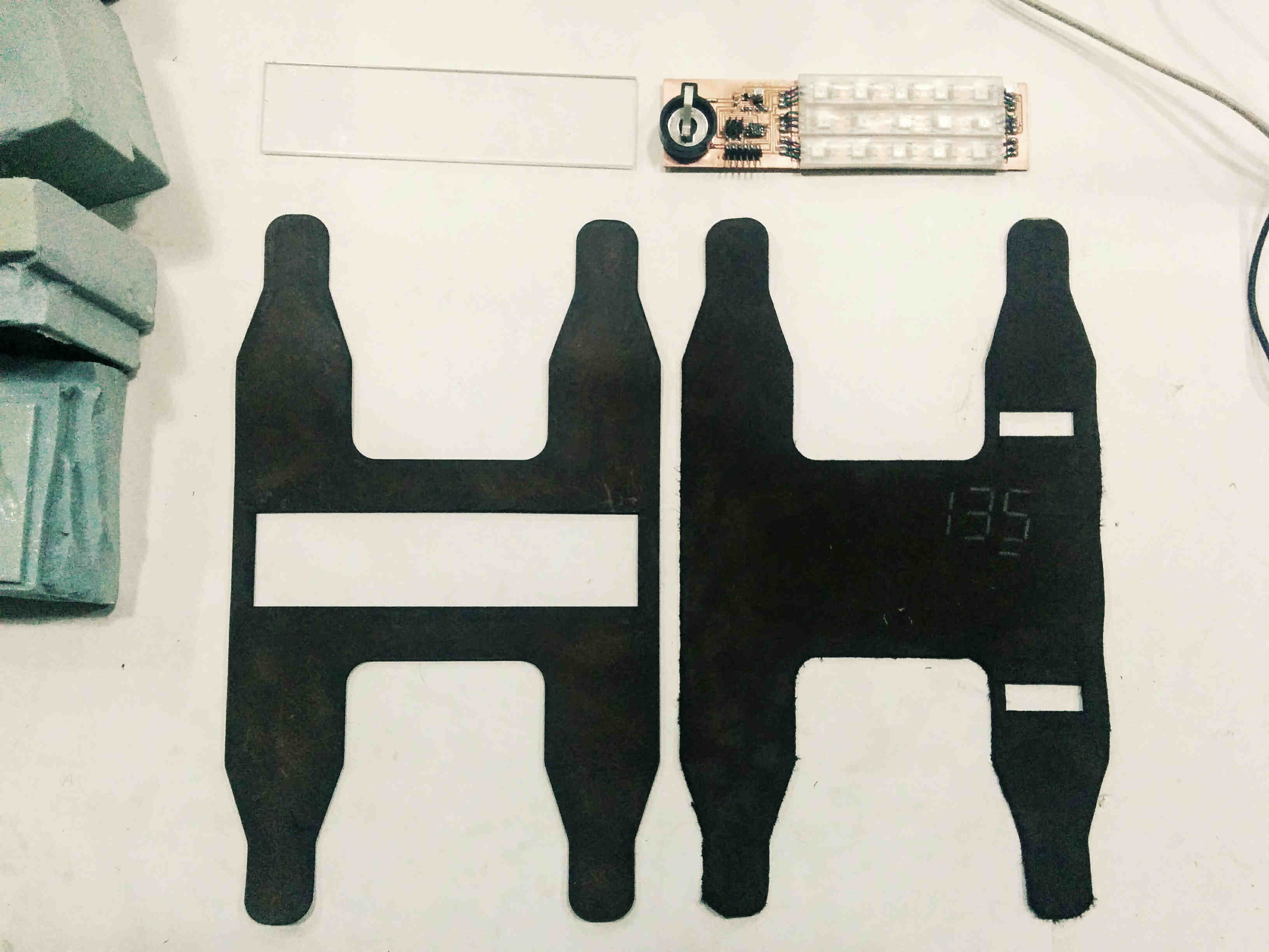
I went into town to get three slices of leather as the base material of the bracelet.
I decided to glue the board to a plexiglass base instead of putting it on the leather directly. This way the board can be more readily exchanged with a follow up version and it adds stability. I designed plexiglass base to be a bit larger than the board to fix it between two leather leyers.
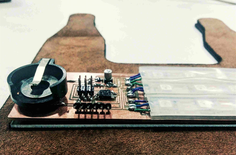
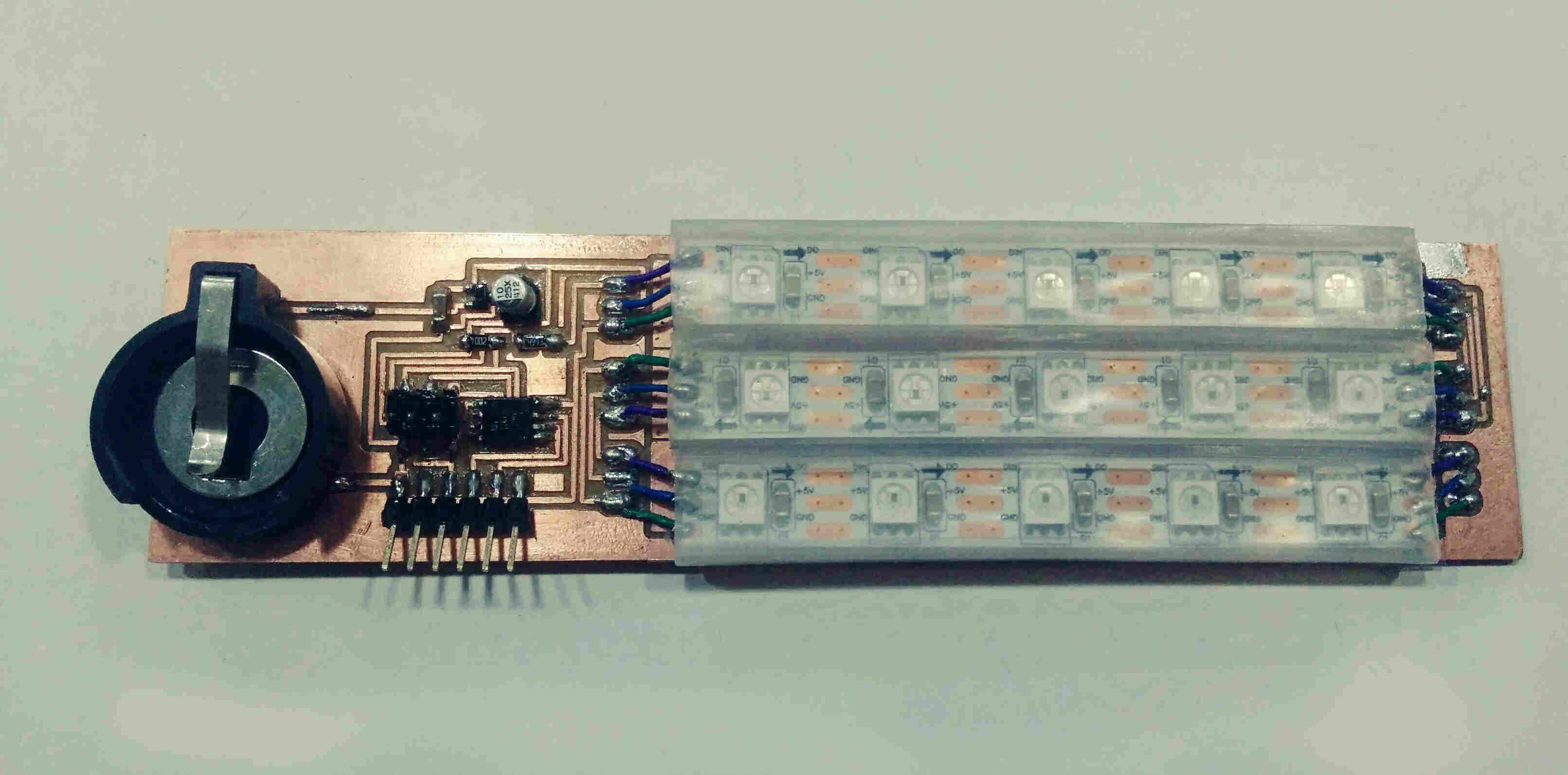
Setting up Final Sense Board
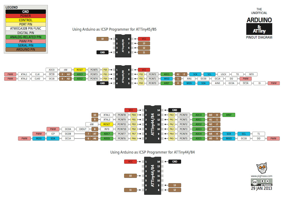
* DataSheet ATTiny 85
* and Arduino / AT Tiny Pin translation:
Hour of Truth
Connected my board for the first time to load boatloader. Error. Tested board connections with the multimeter, resoldered the battery and one foot of the AtTiny85. Tried boatloader again - fail again. Checked all connections with the multimeter proper, back to soldering, then it worked.
Tried the standart "strandtest" code for the adafruit PixelLEDS, with the oddest results: in all three LED rows some lights were on, but at random, not reflected in the code. I double checked my settings -
Board: AtTiny
Processor: AtTiny 85
Clock: internal 8MHz (internal)
Programmer: AVRISP mkll
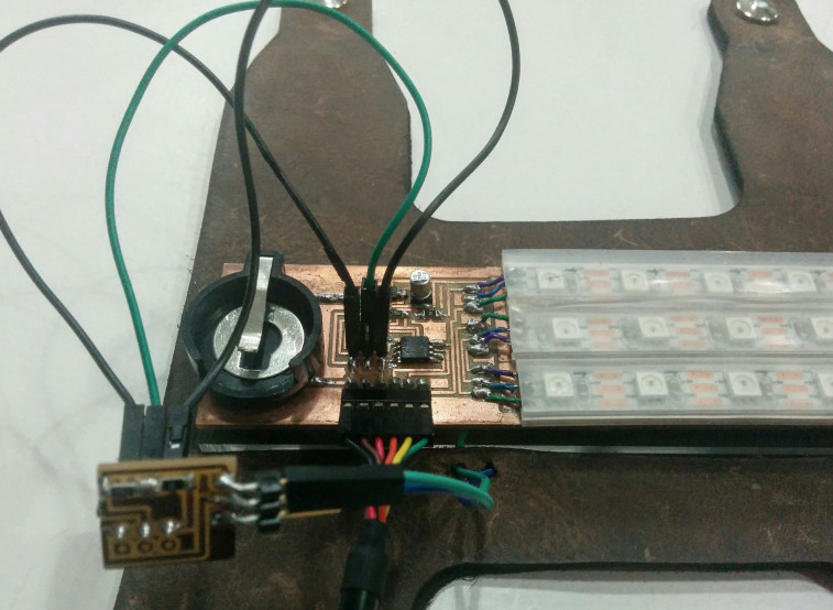
I also checked if my Pixel kind was the right kind reflected in the code, my PIN was set (I use Pin PB1/6/Miso on ATTiny85, which translates to Arduino 1). I also rechecked hardware. All good. But: not working.
Troubleshooting with Arduino Uno & Final Sense Board
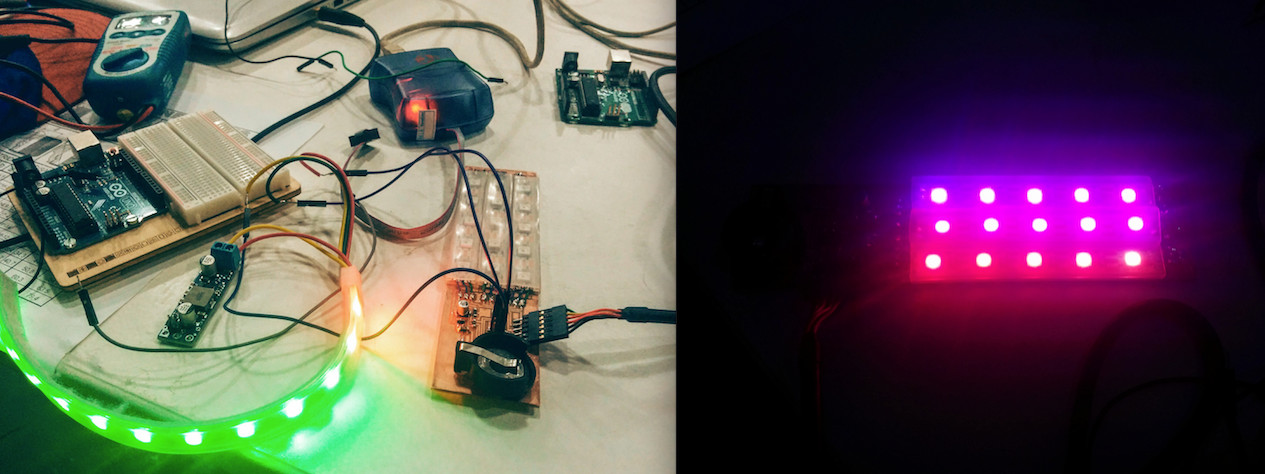
We connected another stripe of Pixel LEDS to an Arduino Uno and ran the strandtest code to double check if these LEDs work. They did.
We then loaded the code into my board, but connected the functioning external LED stripe to it. They blinked, which means my board is functioning.
Next we powered my board LEDs with the Arduino, they worked!
SO: every part functions, just together communication fails.
Problem Identified!!
Adafruit recommends to put a 400-500 Ohm resistor infront of the first LED. This however blocked my signal somewhat. Santi saved the day by exchanging the component with a Zero resistor: And it works!
troubleshooting from Norma D. on Vimeo.
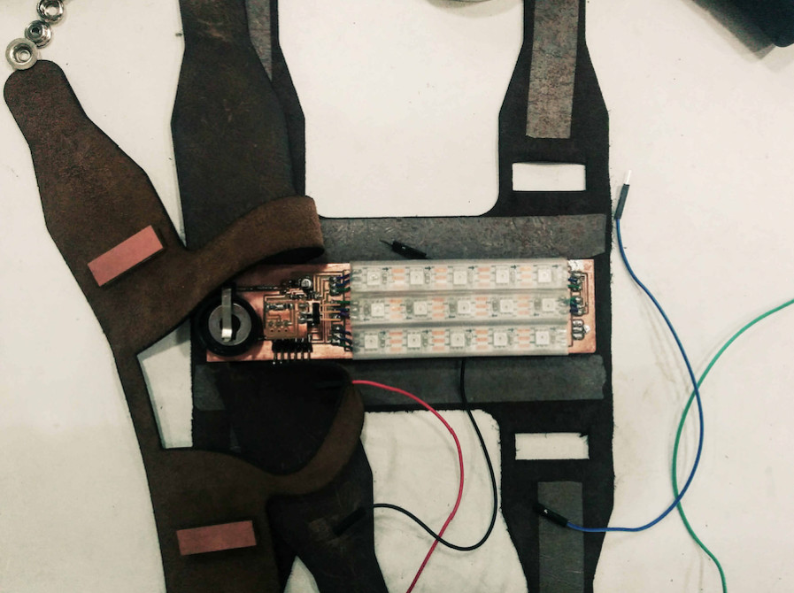
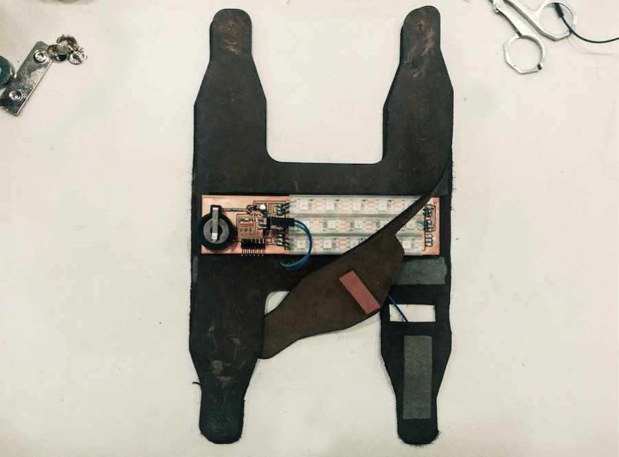
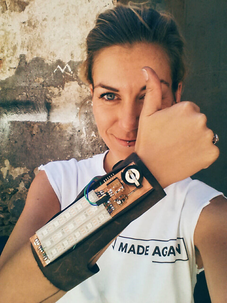
Assembling the Final Sense Cyborg Bracelet
Time to bring it all together : )
Now it´s time to finalise my code.
Back to Code: Tasks
1# adapt and run sensor code (from week 11assignment) on Final Sense
2# select adafruit LED pattern to blink according to sensor value intensity
(3# program interface to visualise sensor data (this will be done for the week 16 assignment)
1# Sensor Code
I translated the working sensor code from week 11 to my new Final Sense set-up: adjusting the pin translations and board specifications in Arduino software.
However, the serial read out does not work. All pin translations are double-checked and correct; the sensor shield connects correctly to the ISP (GND-Mosi-VCC) and hardware is properly connected with voltage flowing.
1# Sensor Code: Troubleshooting
For troubleshooting we adjusted the code and connected a potentiometer to the ISP to regulate the voltage testing if the serial read out corresponds in sensor value.
The serial read out detected sensor value change when the data pin of the potentiometer was connected to the RESET pin on the ISP and not to Mosi, which my code defines as data/sensor pin (=0). I also tried connecting the ISP to my Final Sense sensor shield again, but no value change is detected (the shield of course does not connect to RST but to Mosi). Miso is my LED pin (which also did not work for the sensor). I disconnected the potentiometer and moved my finger over the ISP: no change in serial read out. So the further developed week 13 code only works with potentiometer connecting to RST, but not with my sensor shield and Mosi Pin.
Next: testing final sense sensor set up by connecting it to an arduino uno instead of to my board, running the "analogue read serial" example skript. it works, serial read out corresponds to sensor touch, generating values that seem to make sense.
1# Sensor Code: Solution
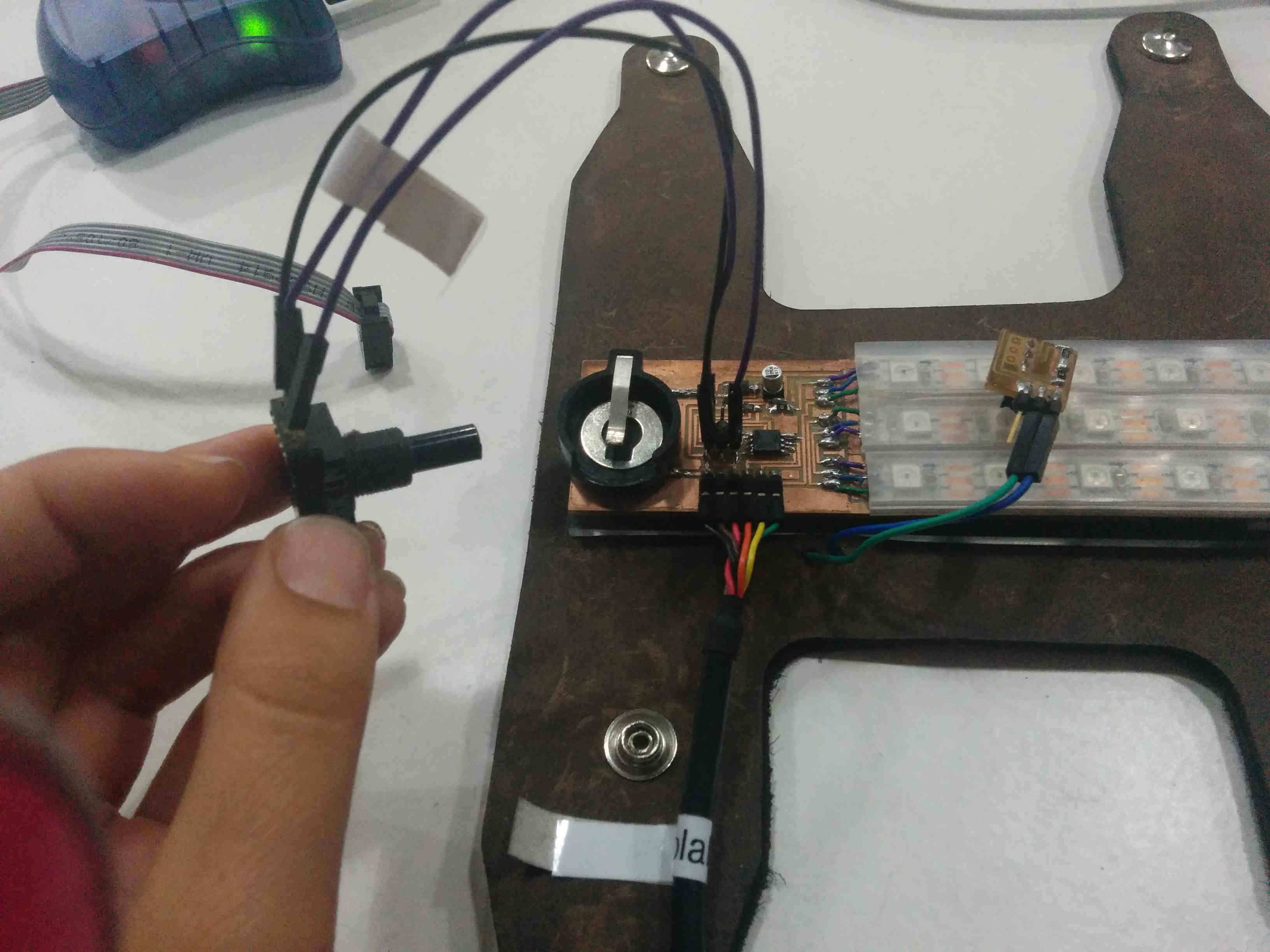
Geuilleme helped me to troubleshoot my board. We set the Sensor Input Pin to SCK --> A1 (in arduino) and rechecked all connections with the help of a breadboard. The solution was a bad soldering on the sensor shield : ( Weird, because I had checked the board with the multimete. After resoldering, the sensor code works! Now I have the jumper cables in between the ISP and the shield though to enable the new Pin connection.
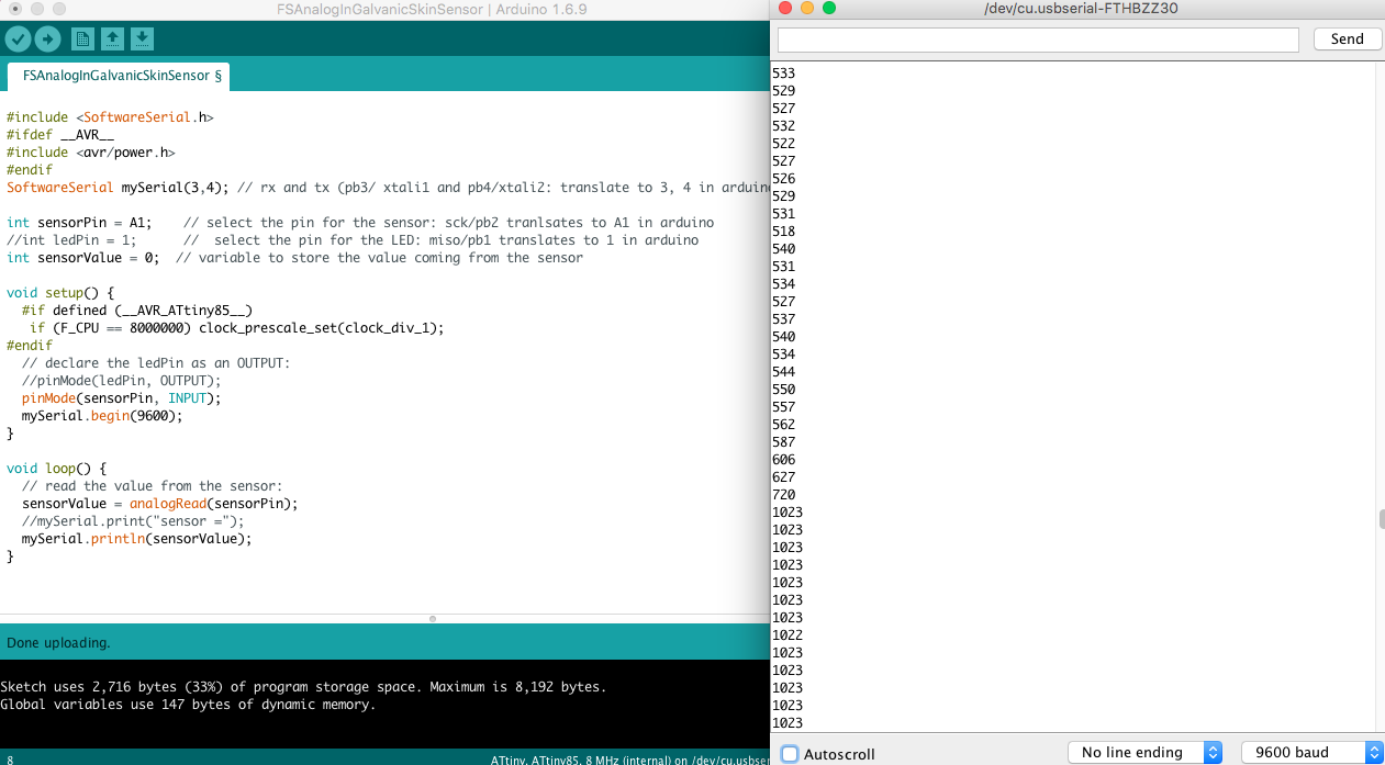
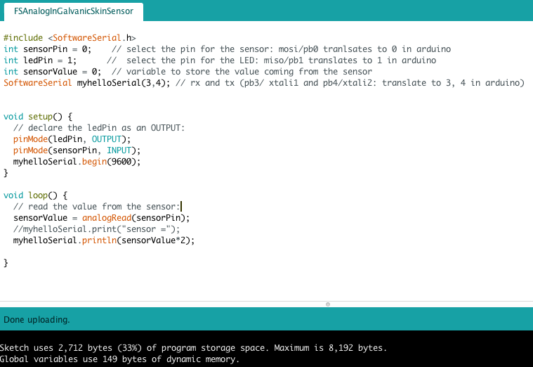
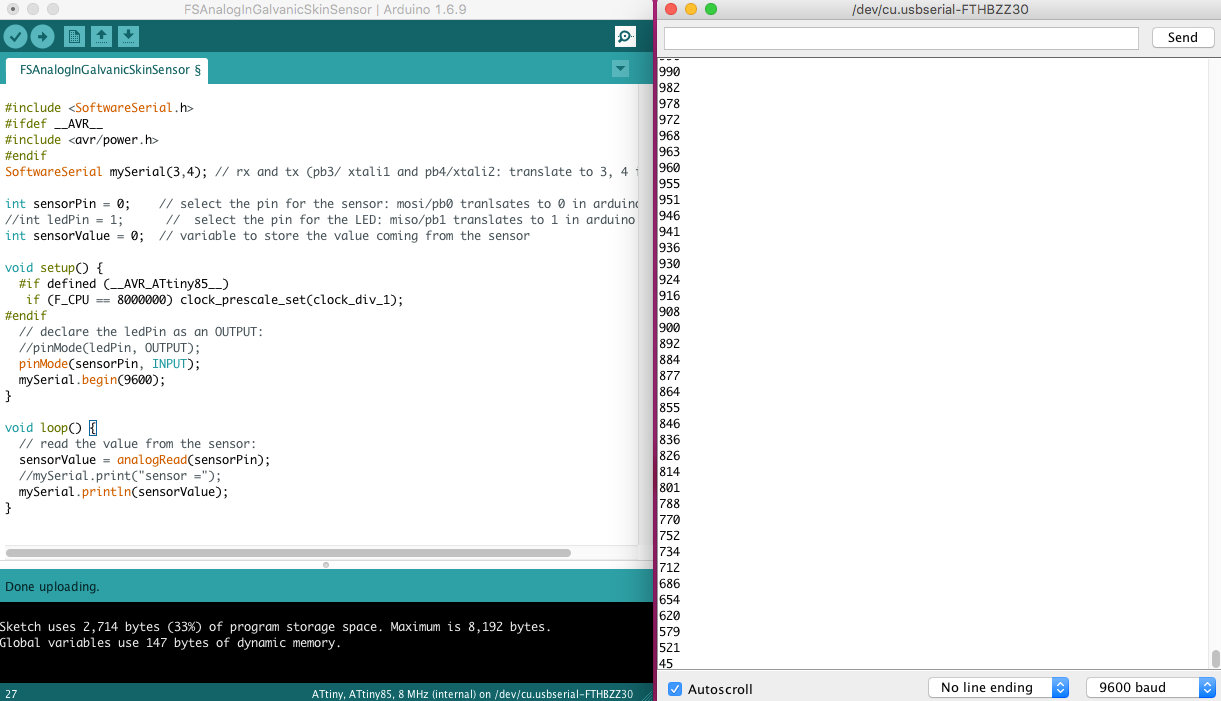
Here is the Sensor Code for Final Sense
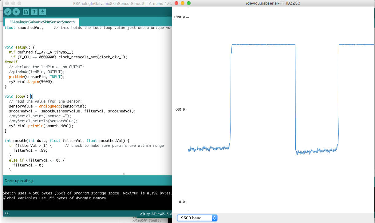
Next step: I included a filter to smooth the value reading: Here is the Galvanic Skin Sensor Smooth Value Code.
2# LEDs corresponding to sensor value
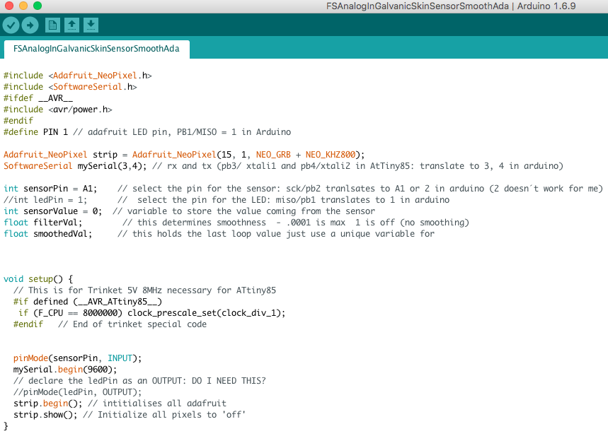
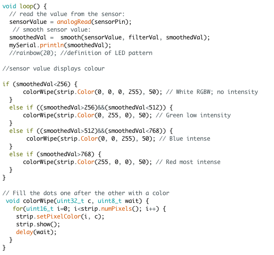
Now I have to decide with LED light pattern I want. I blink through the adafruit strandtest code example and chose the whole led field rainbow, excluding eg the theater circus blinking style and other. This I combine with the Galvanic Skin Sensor Smooth Value Code. The difficulty now is defining colours according to sensor values. I use the if - else if function for this, which I had already written during the week 13 assignment. This is a point of orientation, but as the adafruit NeoPixel LEDs function differently, it´s also a rewrite, not just copy-paste.
Huuuiii - it works!!
LEDS glow according to sensor value: here is the final code!
Final Code from Norma D. on Vimeo.
I had to reign in my ambition a bit: the used colours are fairly ugly. I wanted a rainbow transition between sensor values and nicer neon colours not the classic RGB green-blue-red. But it is what it is, at least for now. Today is final deadline and I still have to finish the Interface programming assignment now 0-o
Self Evaluation
Wow, I actually did this. Can´t quite believe it just yet. See the development page for reflection & self-evaluation.