Week 13: Output Devices
Task
The task is to add an output device to a microcontroller board you've designed and program it to do something. I continue with the prototype for my final project. I will add 5 LEDs to my helloworld board & shield. The goal is to light the LEDs up according to the intensity of the signal of the galvanic skin sensor.
References
* Here is the content page and Neil´s lecture video.
Process
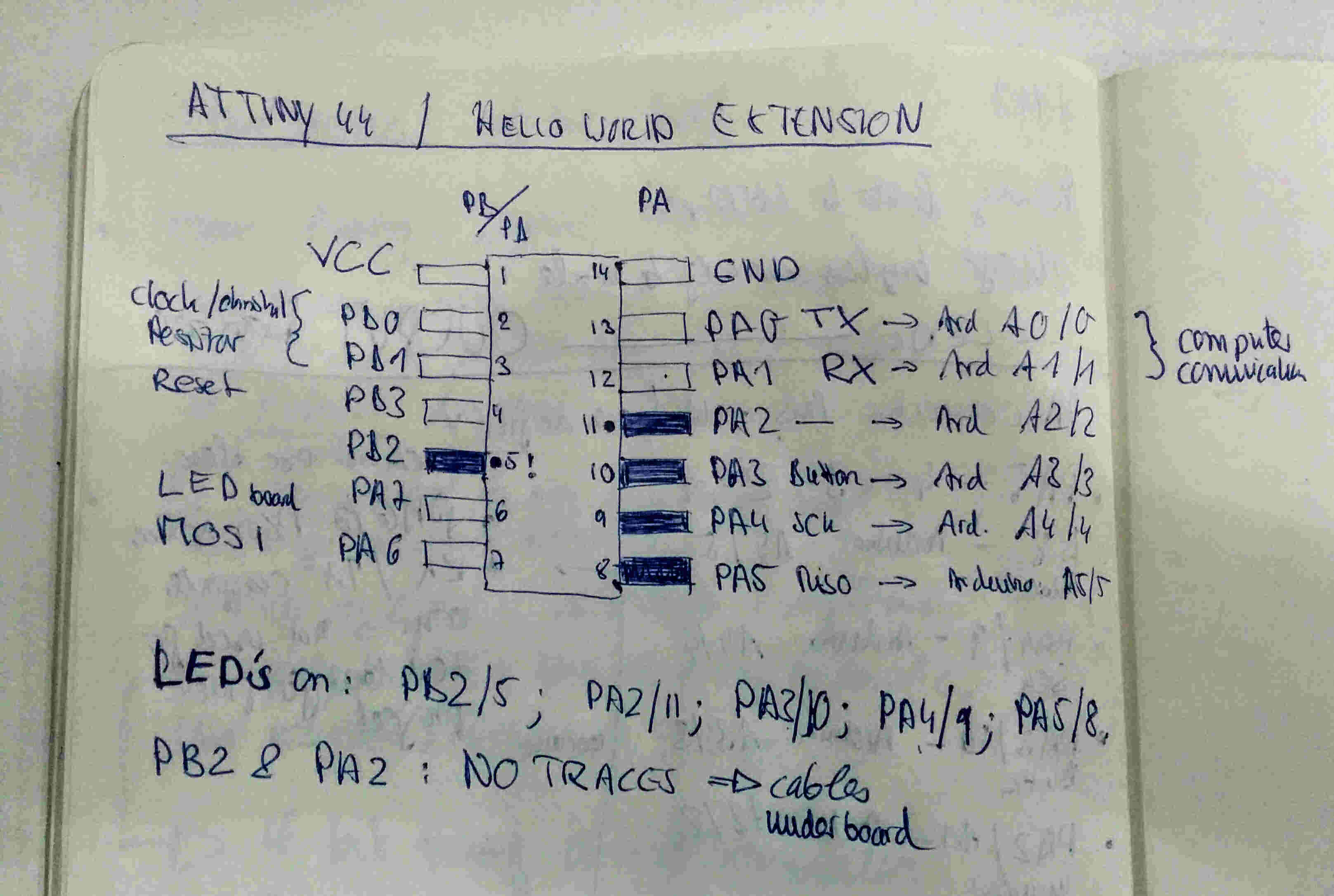
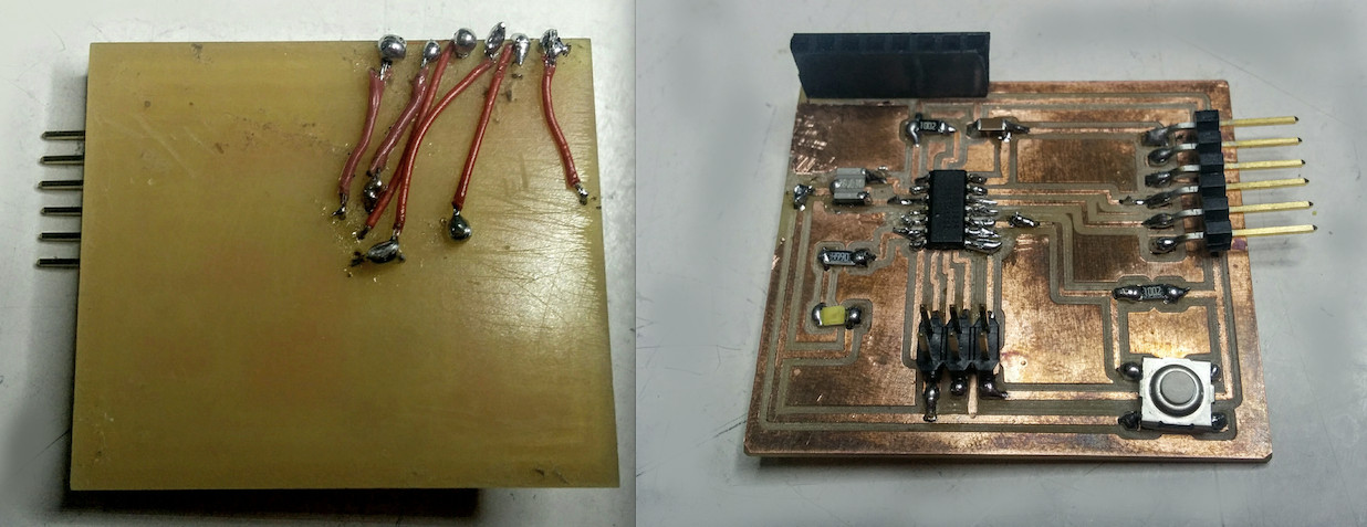
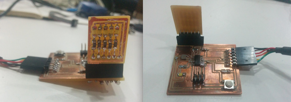
In order to extend my helloworld board I checked which pins on the ATTiny 44 are still free. I connect the LEDs to PB2, PA2, PA3, PA4, PA5 through a header and via "under board" cables by drilling tiny holes in the board. The cables function like cupper traces. An additional connection links the header/the LEDs with GND. For the code the pins need to be re-translated to Arduino. Here is a sketch:
Schemantic & Traces
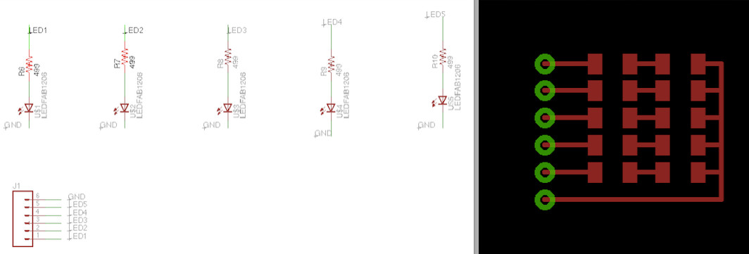
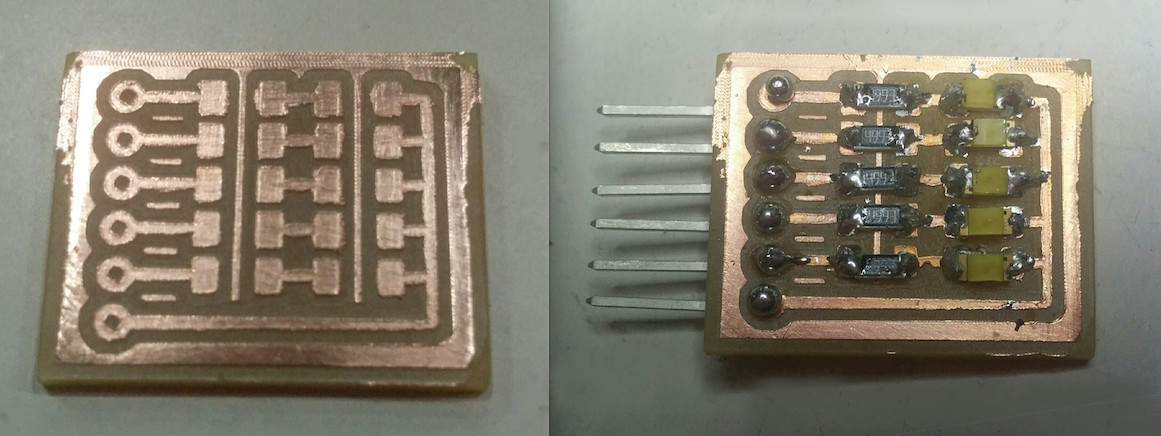
Next I made the schemantic and traces of the LED PCB board in Eagle and prepared the files in Gimp for milling. The board has 5 LEDs, 5 corresponding resitors (499k) and a header. Each Led connects to one pin, all LEDs connect to GND.

Pin Placements for LEDs
* PA2 (Arduino A2) - LED 1
* PA3 (Arduino A3) - LED 2
* PA4 (Arduino A4) - LED 3
* PA5 (Arduino A5) - LED 4
* PB2 (Arduino 8) - LED 5
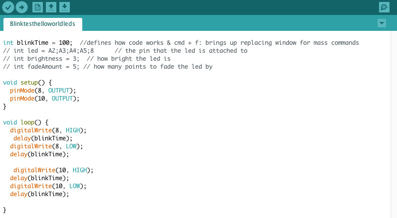
First Test: Arduino blink
* PA2 (Arduino A2) - LED 1: LED 2 is on
* PA3 (Arduino A3) - LED 2: LED 4 blinks, turns off
* PA4 (Arduino A4) - LED 3: LED 4 blinks, turns off
* PA5 (Arduino A5) - LED 4: LED 4 blinks, then stays on
* PB2 (Arduino 8) - LED 5: LED 5 is on
Blink Troubleshoot
* checked connections with multimeter, worked
* realised had used 499k resitors. desoldered, replaced with 100ohm; double check direction LED is soldered on board.
* Ferdi´s hack: cut trace connection between on-board button and it´s resitor to use pin only for LED
Second Test: Arduino blink
* PA2 (Arduino A2) - LED 1: LED 1 glows weakly, LED 2 is on
* PA3 (Arduino A3) - LED 2: LED 1 is on
* PA4 (Arduino A4) - LED 3: LED 1 glows weakly, LED 3 is on
* PA5 (Arduino A5) - LED 4: LED 1 glows weakly, LED 4 is on
* PB2 (Arduino 8) - LED 5: LED 1 glows weakly, LED 5 is on
Blink Troubleshoot
* rechecked pin - LED connections, LED1 is PA3 not PA2; LED2 is PA2 not PA3; others are correct
* new code: blink through LEDS: all working except LED5 due to broken solder connection; resoldered it and now it works - finally.

Result: muy bien
5 LEDS Blink week 13 from Norma D. on Vimeo.
Download All Files