Exercise 15: Networking and Communications
Assignment 15: Design and build a wired &/or wireless network connecting at least two processors.
I decided to connect my Input and Output boards.
I2C
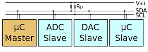
Inter-integrated Circuit (I²C or I2C or IIC) is a protocol designed for connecting multiple integrated circuits and making them communicate with a controller. The controller is called "master" and the other chips are the "slaves". This bus is intended for short distance communications, and it only requires two wires to exchange information. The protocol was invented in 1982 by Philips, but since October 10, 2006, no licensing fees are required to implement the I²C protocol.
Each I2C bus consists of two signals (Fig. 1): SCL and SDA. SCL is the clock signal, and SDA is the data signal. The clock signal is always generated by the current bus master. Messages are broken up into two types of frame: an address frame, where the master indicates the slave to which the message is being sent, and one or more data frames, which are 8-bit data messages passed from master to slave or vice versa. Data is placed on the SDA line after SCL goes low, and is sampled after the SCL line goes high. A well-done tutorial on I2C has been published by Sparkfun.
Programming the network
The AVR ATmega microcontroller series (the one used in the Arduino board) contains builtin support for interfacing the microcontroller to a two-wire bus, called TWI (Two Wire Interface), that is the I2C bus. ATtiny microcontrollers do not have hardware support, but it is possible to emulate it through bit banging, that is using software instead of dedicated hardware.
Googling "ATtiny I2C" I found the "I2C (master and slave) on the ATtiny85" page on the official Arduino blog. The page contains TinyWire Master and Slave libraries modeled after the standard Arduino Wire library. However, the available libraries are quite outdated and works on the Attiny85 only.
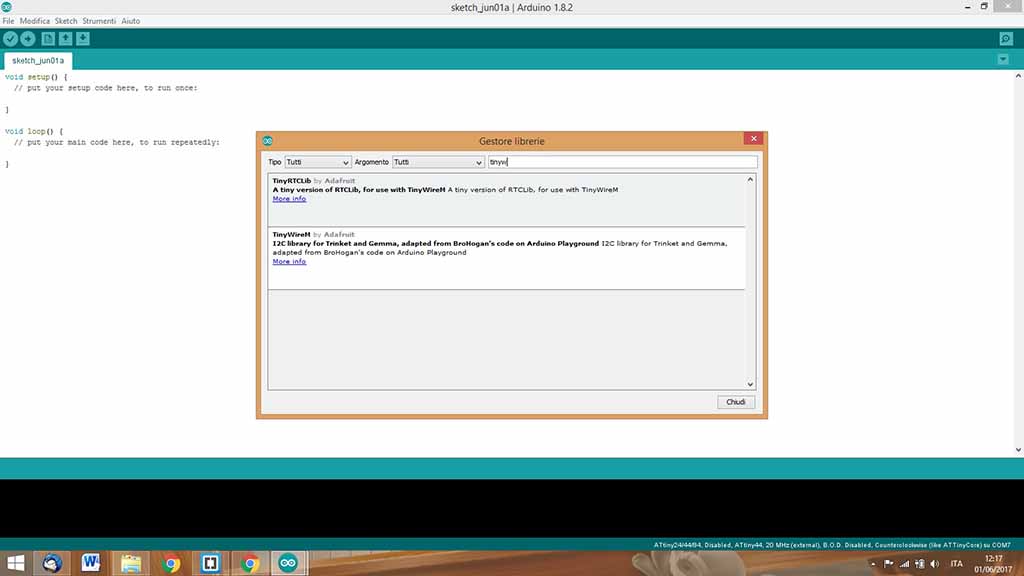
I discovered that, during the years, the TinyWireS library (the ending S stands for Slave) has been improved including support for the ATtiny44. I installed it directly from the Arduino IDE from Sketch --> #include library --> Manage Libraries" (Fig. 2).
Unfortunately, the slave counterpart was not available. Emanuele pointed me to a more recent version of the TinyWireM library (the ending M stands for Master) with support for the ATtiny44 too, and he put online on his wiki a .ZIP file ready to be imported into the Arduino IDE. I downloaded the ZIP and again I installed the library from the Arduino IDE.
Now that the two libraries were installed, I started looking at the examples for the code. I found that another italian student, Silvia Palazzi, was working with TinyWire and the ATtiny44. She used the ATtiny as a Slave only chip, but it still was a starting point!
I combined the code of my output assignement (the servo motor board) with the code for recieving I2C bytes. The I2C slave library is quite simple: you just have to define and address for the device (I choose the number 5) and initialize the bus with this address during the setup phase. Then, similar to the Serial library, the library includes an "available()" method for checking if any data is available on the bus, and a "receive()" method for reading the byte from the buffer.
I uploaded the following code for the I2C slave onto the output board:
    #include <TinyWireS.h>
    #include <Servo.h>

    #define I2C_SLAVE_ADDR  0x05  // i2c slave address (5) - hardcoded
    #define SERVO_PIN PIN_A7
    #define I2C_MSG 0x01

    Servo myServo;
    int angolo = 0;

    void setup(){
    myServo.attach(SERVO_PIN);
    myServo.write(0);
    TinyWireS.begin(I2C_SLAVE_ADDR);
    }


    void loop(){
    byte byteRcvd = 0;
    if (TinyWireS.available()){
    byteRcvd = TinyWireS.receive();
    if (byteRcvd == I2C_MSG) {
      moveServo();
    }
    }
    }

    void moveServo() {
    angolo = (angolo + 10) % 180;
    myServo.write(angolo);
    delay(100);
    }
Finding documentation and examples for running an I2C slave on the ATtiny was quite easy; for the master side I found that Silvia and the other guys at FabLab Toscana used a stock Arduino board (which have I2C hardware support). However, the examples contained inside the TinyWireM library were simple enough to make me understand the library and write a scketch in a couple of minutes.
Specifically, the Tiny85_Temp example shows that the I2C library must be initialized as usual in the setup function. Then, sending a byte is just a matter of invoking "beginTransmission()" specifying the destination address, "send()" for sending the data, and finally "endTransmission()" closes the transmission.
I combined the master code and part of the code for reading the phototransistor, and I created the code for the Master. The final sketch reads the value from the pin A3, where the phototransistor is attached, and waits indefinetely until the value reaches 128 or above (medium light). Hence, it sends a specific byte (0x01) over the I2C bus the the ic with the address #5.
    #include <TinyWireM.h>

    #define I2C_SLAVE_ADDR  0x05
    #define PHOTO_PIN A3
    #define I2C_MSG 0x01

    void setup(){
    TinyWireM.begin();
    pinMode(PHOTO_PIN, INPUT);
    }

    void loop(){
    while (analogRead(PHOTO_PIN) < 128) { }
    TinyWireM.beginTransmission(I2C_SLAVE_ADDR);
    TinyWireM.send(I2C_MSG);
    TinyWireM.endTransmission();
    delay(1000);
    }
Both the master and the slave TinyWire libraries define the two pins used by each microcontroller. These values are microcontroller-depended, and for the ATiny84/44 are:
    #  define DDR_USI           DDRA
    #  define PORT_USI          PORTA
    #  define PIN_USI           PINA
    #  define PORT_USI_SDA      PORTA6
    #  define PORT_USI_SCL      PORTA4
    #  define PIN_USI_SDA       PINA6
    #  define PIN_USI_SCL       PINA4
    #endif
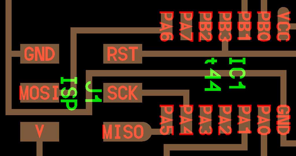
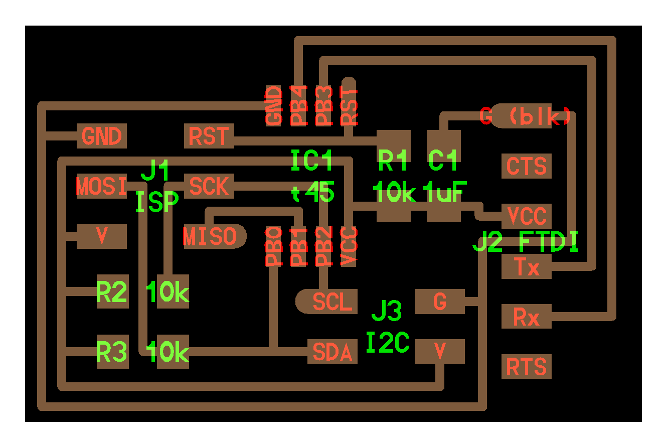
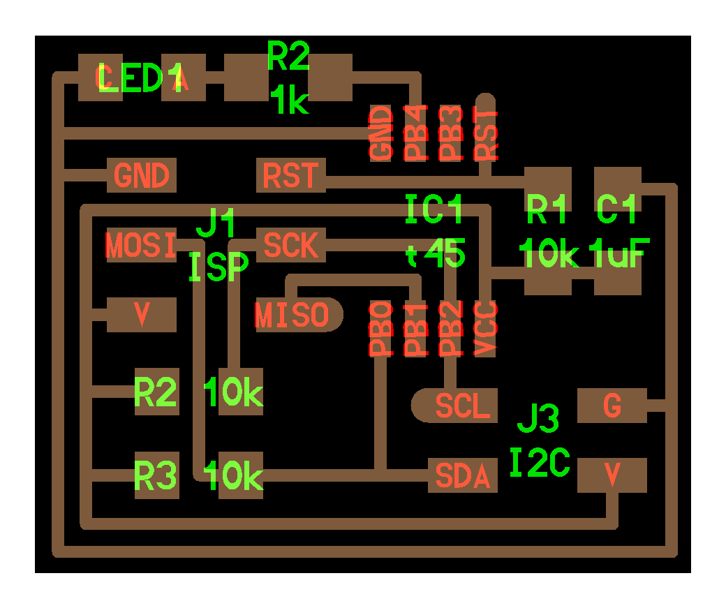
These two pins are already exposed on by board: they are connected to the SCK (A4) and MOSI (A6) pins of the ISP header (Fig. 3). This header is used for programming the board, so it is available on the Hello board and on all the modified boards (input, output, hello plus button etc...). Moreover, this header exposes VCC and GND, so I could power through FTDI only the master and power the slave through these pins.
Connecting the network
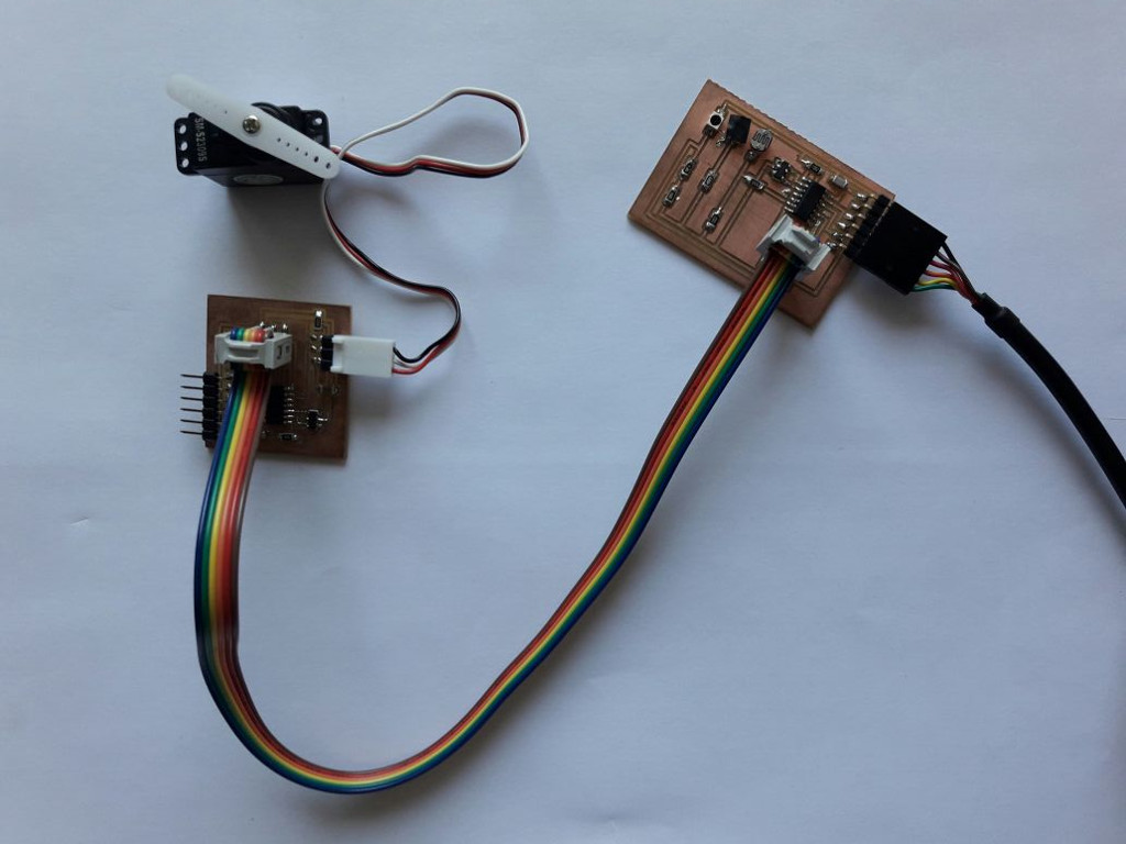
At first I used the simple flat cable to connect directly the two 6 pins ISP headers (Fig. 4). However, nothing happened.
I double checked the code, but everything seemed ok. Then, I googled a bit and I also checked the hello I2C boards available on the FabAcademy website: I discovered that pull-up resistores were needed on the SDA and SCL lines.
Problem: Pull-up resistors
I re-read carefully the tutorial and I discovered that the I2C bus drivers are "open drain", meaning that they can pull the corresponding signal line low, but cannot drive it high. This bus contention mechanism eliminates the potential for damage but requires each signal line has a pull-up resistor on it, to restore the signal to high when no device is asserting it low.
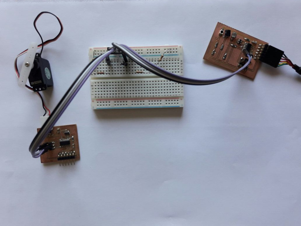
Since I did not created two custom boards but I reused older ones, my SDA and SCL lines did not have pull-up resistors. Hence, I cut the wires and put pull-up resistors on the two lines (I used a breadboard to avoid floating resistors).
Strangely enough, I started with 10 KOhm as used by Niel, but no luck. Hence, I tried to change the values: using 4.7 KOhm on the SDA data lines made the network work as expected, even without resistors on the clock line. On the contrary, I discovered that the network works without pullup resistors on the SDL lines or with at least 20 KOhm on it (Fig. 5).
On Stackexchange I found a thread discussing this issue and I found this interesting post: The library you use, and the libraries it depends on (Wire), enable the internal pull-ups of the ATMega. These are weak pull-ups, and in normal use, supplement any external pull-ups (two resistors in parallel). Due to the relatively high resistance of 20k to 70k, they do not cause much if any issues with external ones in use. What happens when the I2C pullups are omitted? Now without external resistors, the weak internal pull-ups are the only thing driving the line high. Depending on your board layout, the speed of your i2c line, how often you access it, external interference, etc, they might work, they might not. You lucked out. You do have pull-ups, just not ones you expected. The moral is: I was lucky, but this does not explains why 20 K is fine but 10 is not. I will investigate this issue if I will have to used I2C in my final project.
Nevertheless, I found the right combination of pull-up resistors and I got my two board talking over an I2C network!