Exercise 13: Input Devices
Assignment 13: Measure something adding a sensor to a microcontroller board that you have designed and read it.
In this assignment I decided to test part of my final project: the solid that I made in "Molding and casting" assigment will have to turn on if will be inserted in the right place. A more simple way is to use reed switch and magnets, but I would try with led and sensors. I made two attempts: first Photoresistors, the Phototransitors.
First attempt: led-photoresistors-gray card
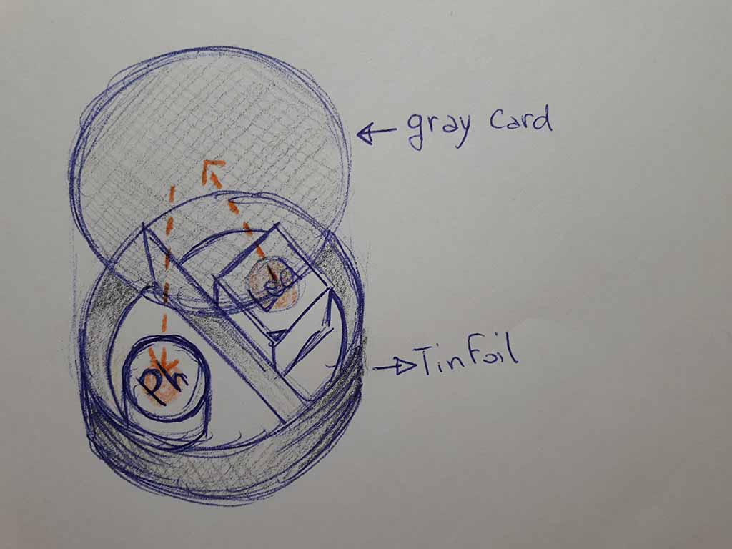
The idea is that the led light reflects on a gray cardboard and it modifies the Photoresistor value by giving values that will trigger other impulses (Fig. 1). At the moment, I just need to know if the "led-photoresistors-gray card" system works and to verify that values are obtained with different gray scales. I decided to test two Photoresistors connected to different resistor size to have different attempts.
Drawing and milling the board
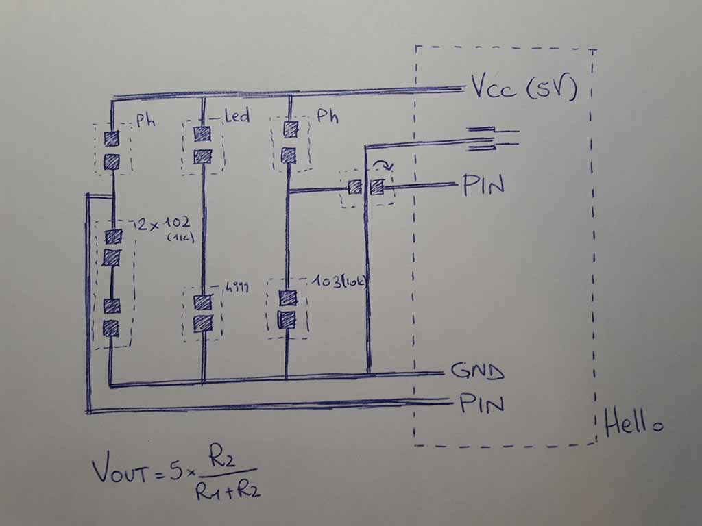
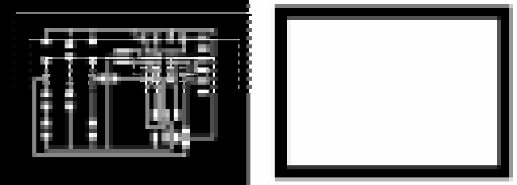
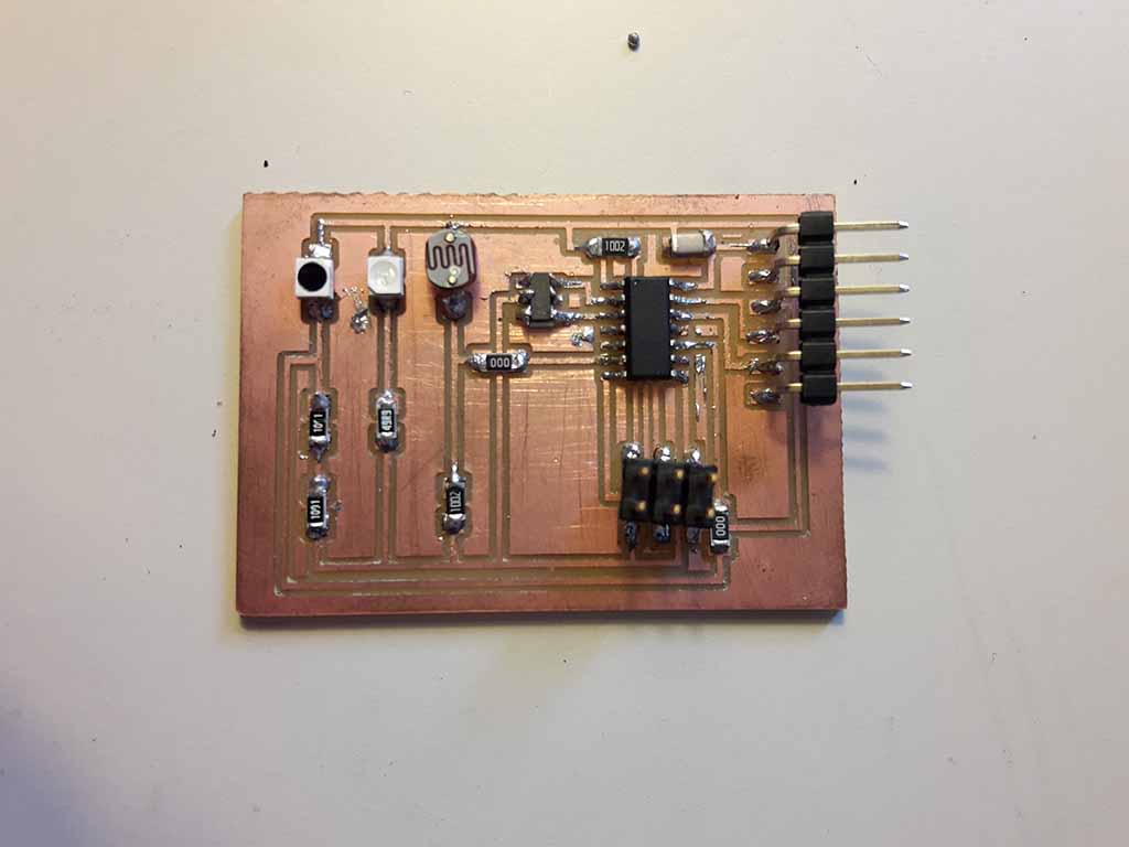
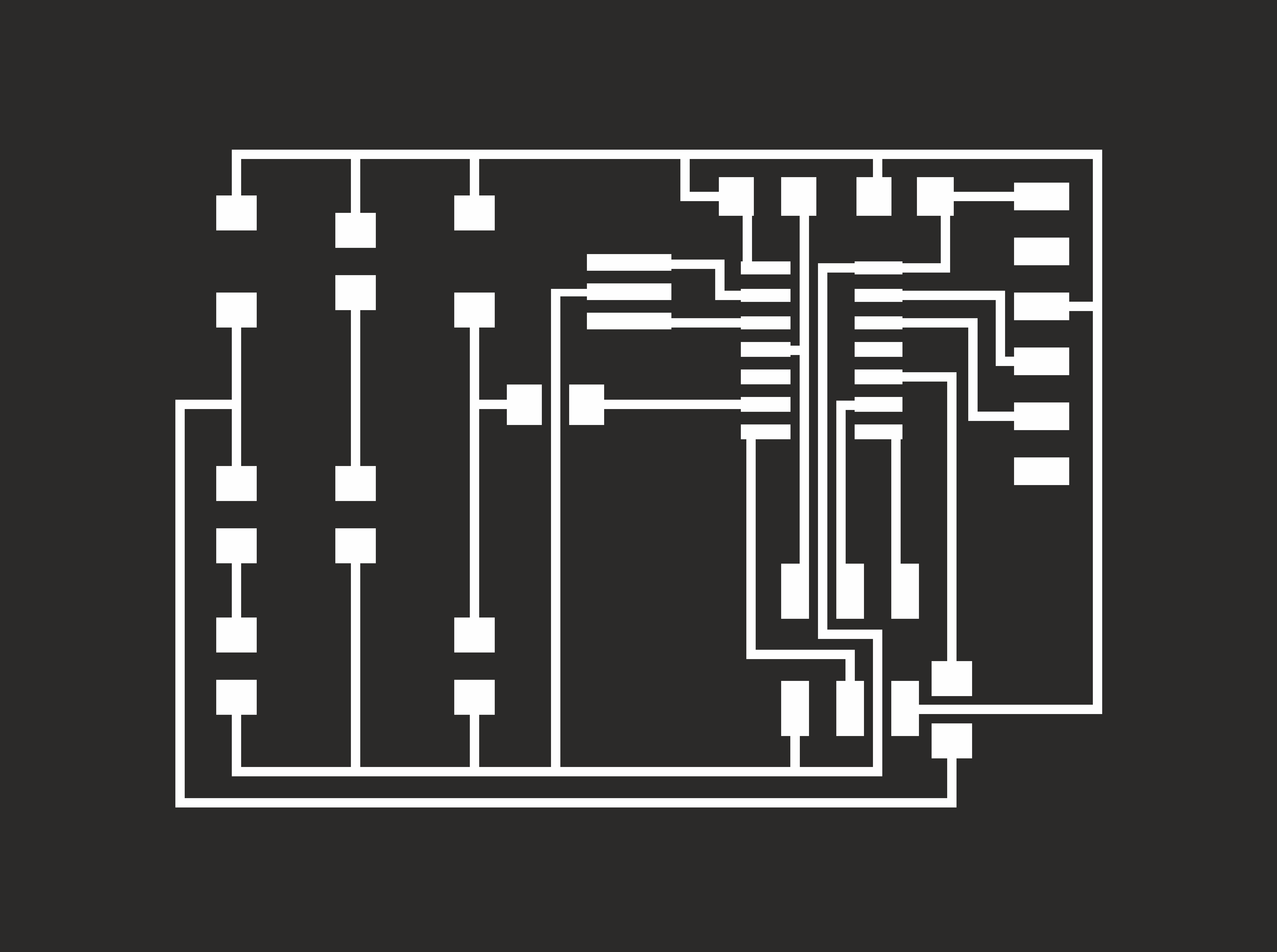
I used Eagle to draw the board starting from the Hello. Below the scheme of my board (Fig. 2) and the PNG that I milled (Fig. 3).To prepare the file for the milling machine I used Fab Modules and then I moved on the Roland MDX-40 following the same process of the previous assignments. The milling phase went well also because, after milling four times the Hello, the Roland does not make me afraid.
Soldering the board
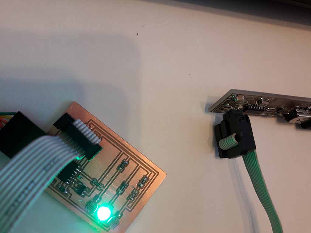
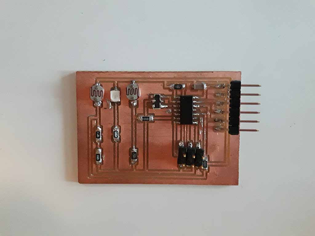
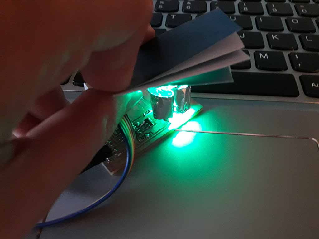
I decided to use Photoresistors hole components, but I knows that it's better to use SMD components. Below you can find the part related to SMD components. I had some problems with soldering the board, because at the end the multimeter marked a short circuit. After some attempt I found the problem: the soldering of a bridge were touched. Removed the problem, I connected the board to the pc with the TDI cable and the led turned on (Fig. 4). I have set the fuses but there was another "Error" whaen I tried to upload the program, so I tried to better solder the Resonator and the error disappeared. Below you can see my final soldered board (Fig. 5).
Programming the board
Enrico suggested me to use Arduino IDE to program the board. First of all I downloaded and installed Arduino IDE on my computer following this link.
Then, I followed this process to install ATtiny in IDE:
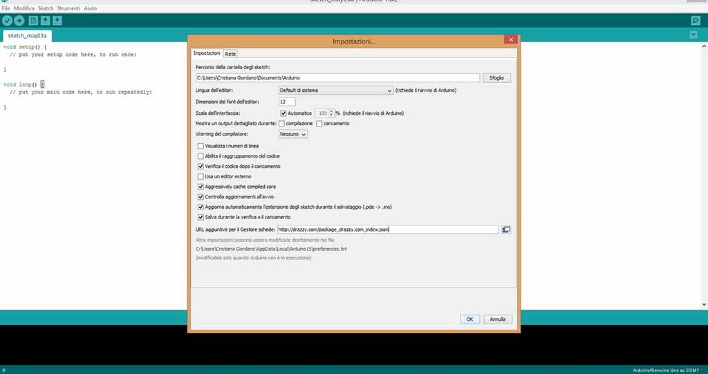
I pasted the URL http://drazzy.com/package_drazzy.com_index.json into "Additional Board Manager URLs" clicking on "Preferences" into "File" (Fig. 6);
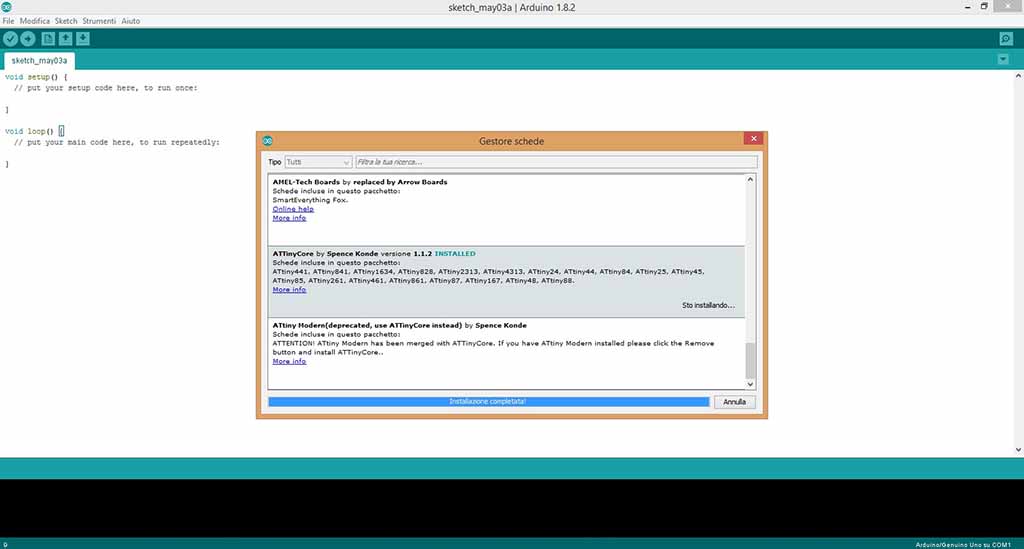
I installed "ATtiny Core" into the "Board Manager" clicking on "Tools" (Fig. 7);
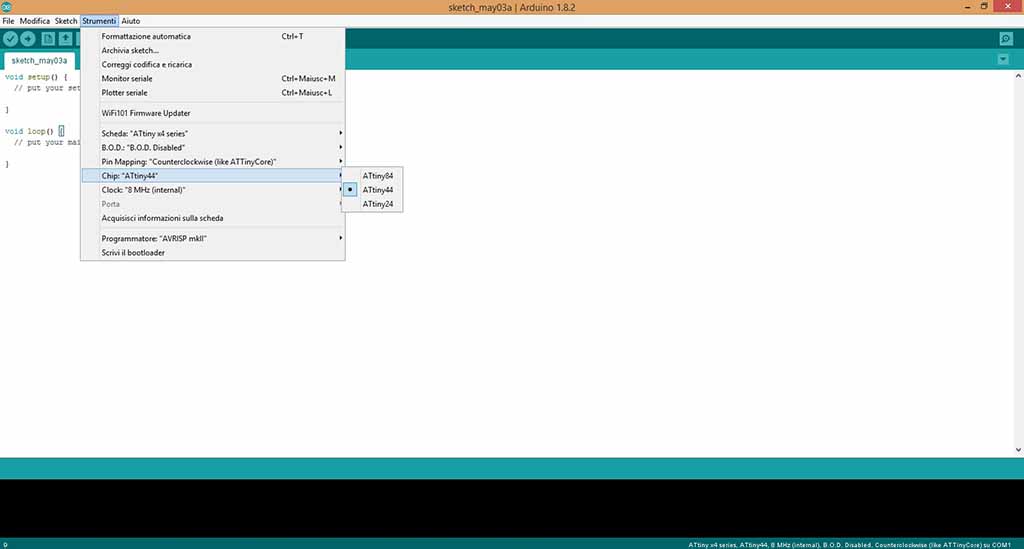
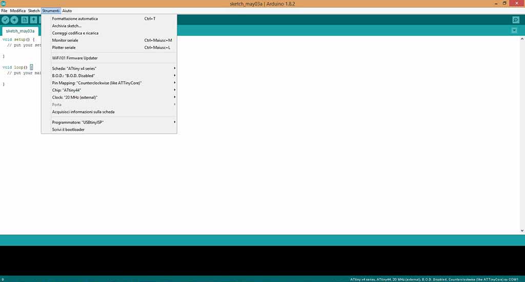
I selected "ATtiny x4 series" into "Boards" and finally "ATtiny 44" into "Chip" clicking on "Tolls" (Fig. 8).
Finally I setted up these default parameters (Fig. 9):
B.O.D. Disabled
Pin mapping Counterclockwise
Chip ATtiny44
Clock 20 MHz
Programmer USBtinyISP
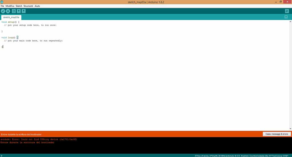
Therefore I tried to "Burn Bootloader", but there was an error (Fig. 10). So I searched on web and I found a Driver Installer for Windows that you can download clicking on this link.
I wrote this code to program the board:
        const int oneSensorPin = A3;
        const int twoSensorPin = A7;
        const int baselineTemp = 20.0;

        void setup() {
        Serial.begin(9600);
        }

        void loop() {
        int oneSensorVal = analogRead(oneSensorPin);
        delay(5000);
        int twoSensorVal = analogRead(twoSensorPin);
        delay(5000);

        Serial.print("Sensor Value One: ");
        Serial.print(oneSensorVal);
        Serial.print("Sensor Value Two: ");
        Serial.print(twoSensorVal);
        }
After checking it, I launched it using IDE buttons. Then I tried to open the Serial Monitor, but IDE said that was a problem with the Serial Port. So I tried to change it setting that IDE suggested. I setted up COM7 instead of COM8) and the Monitor opened correctly.
Reading the values on the Serial Monitor
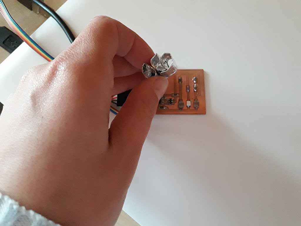
I prepared a sort of box using aluminum paper to guide the light of the Led to the Photoresistors and I put it on the board (Fig. 11). Then I printed a gray scale (Fig. 12) that I put on the aluminium to try to reflect the Led light on the sensors (Fig. 13).
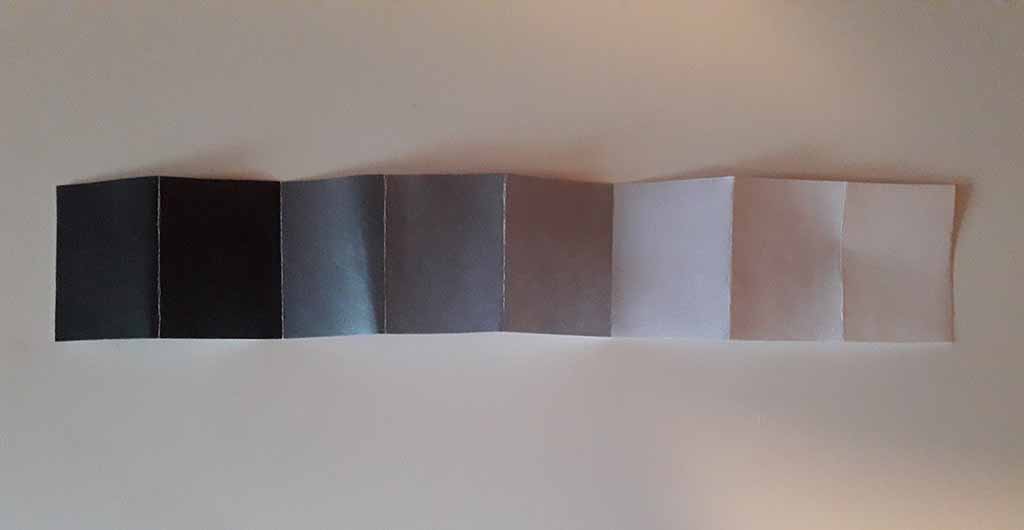
Therefore I red the values on the Serial Monitor using three color card: black, medium gray and with.
Using a black card, the values were:
        Sensor Value One: 25
        Sensor Value Two: 29

        Sensor Value One: 27
        Sensor Value Two: 19

        Sensor Value One: 12
        Sensor Value Two: 31

        Sensor Value One: 11
        Sensor Value Two: 9

        Sensor Value One: 11
        Sensor Value Two: 8

        Sensor Value One: 12
        Sensor Value Two: 9
Using a medium gray card, the values were:
        Sensor Value One: 12
        Sensor Value Two: 21

        Sensor Value One: 13
        Sensor Value Two: 27

        Sensor Value One: 18
        Sensor Value Two: 12

        Sensor Value One: 16
        Sensor Value Two: 12
Using a white card, the values were:
        Sensor Value One: 24
        Sensor Value Two: 84

        Sensor Value One: 33
        Sensor Value Two: 43

        Sensor Value One: 56
        Sensor Value Two: 37
As you can see, the values are not realiable and stable. The range is too large and the system does not work well with gray gradations. So I decided to try using SMD Phototransistors.
Second attempt: Phototransistors
This time I used one SMD Phototransistor instead of one Photoresistor (Fig. 14).
Programming the board
I used this code:
        const int SensorPin = A3;

        void setup() {
        Serial.begin(9600);
        }

        void loop() {
        int SensorVal = analogRead(SensorPin);
        delay(1000);

        Serial.print("Sensor Value: ");
        Serial.println(SensorVal);

        }
Reading the values on the Serial Monitor
With natural light I read this values under the sun light ...
        Sensor Value One: 976
        Sensor Value One: 977
        Sensor Value One: 978
        Sensor Value One: 977
... this values when the sensor was totally covered ...
        Sensor Value One: 261
        Sensor Value One: 240
        Sensor Value One: 218
        Sensor Value One: 197
        Sensor Value One: 197
        Sensor Value One: 191
        Sensor Value One: 179
        Sensor Value One: 177
        Sensor Value One: 178
        Sensor Value One: 276
... and finally this values when the sensor was in the shadow (covered by the card) ...
        Sensor Value One: 467
        Sensor Value One: 467
        Sensor Value One: 465
        Sensor Value One: 470
        Sensor Value One: 474
        Sensor Value One: 474
        Sensor Value One: 488
I also tried the system in a closed environment with the light of the Led, but the values were always very low.
Without obstruction on the sensor ..
        Sensor Value One: 8
        Sensor Value One: 7
        Sensor Value One: 6
        Sensor Value One: 6
        Sensor Value One: 6
... partially covered with gray scale ...
        Sensor Value One: 4
        Sensor Value One: 4
        Sensor Value One: 3
        Sensor Value One: 3
        Sensor Value One: 2
        Sensor Value One: 4
        Sensor Value One: 4
        Sensor Value One: 5
... and totally covered.
        Sensor Value One: 0
        Sensor Value One: 1
        Sensor Value One: 1
        Sensor Value One: 2
        Sensor Value One: 1
        Sensor Value One: 2
        Sensor Value One: 2
        Sensor Value One: 1
        Sensor Value One: 2
        Sensor Value One: 3
        Sensor Value One: 2
        Sensor Value One: 1
After these tests I can conclude that Phototransistors performs much better and they are more reliable than the Photoresistors. However in my project I will have to use a different Phototransistor, sensible to visible light produced by Leds, or a completely different solution (for example physical contacts, etc.).
Download area
Download my schematic Eagle file
Download my .png file for the traces
Download my .png file for the edge
Download my file for milling the traces with Roland MDX-40
Download my file for milling the edge with Roland MDX-40