Study, study, study! All facets of Serial world
Up to know, I've faced with serial many times: serial ports, serial communication, ISP, serial communication, serial interface.
But as it sometimes is, seeing many aspects of the same topic may confuse you. Did I really know what SERIAL really meant?!NO.
I spent most of my weekly time studying and reading because I previously knew that passing on to practice would have scared me so much if I didn't know
what I was (quite) exactly going to do, that I would have gone mad.
So, time to better know SERIAL...
SERIAL IS A PROTOCOL - comparisons with Parallel communication
As I said, talking about serial means everything and nothing at the same time, but if there's something common to all speeches you may hear about
it is that they refer to a PROTOCOL. A protocol is an amount of rules that determines how communication, data exhange and interpretation must be done
on the Internet. Does something light up when I say OSI Layers? (If not, see more here)
In few words, Serial communication protocol is a group of rules that determine one of the way Network layer is used for - network communication is used for server-->computer-->board-->microcontroller communication).
In fact, there's no just
serial communication, there's also PARALLEL communication protocol.
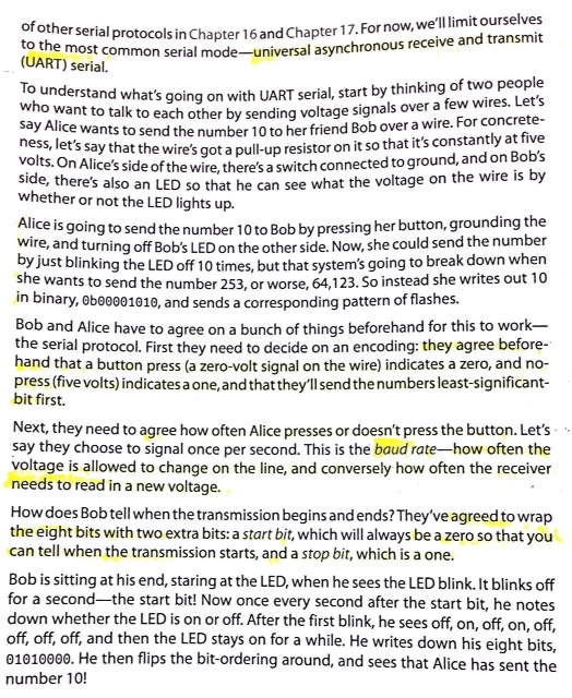
Ok Silvia, but in what can I see their differences? It's all mostly about how data are divided into packages (and then bits) and sent from transmitter microcontroller to the receiver one
, so mainly about
how rules find practical realization. I found a really nice explanation on Sparkfun website.
In the picture below, I report the scheme that summarize the main difference in data exchange among the two protocols:
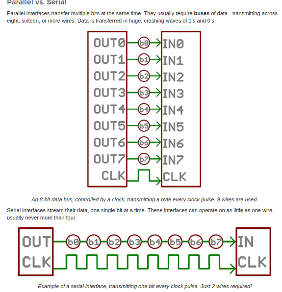 As you see, given that green lines are physical wires, there's a great saving in wire numbers (2 for Serial vs 9 for Parallel) but on the other hand,
while eight bits can be sent all together in a clock pass with Parallel communication, with Serial communication you can just send a bit per clock pass and then the message
is rebuilt from the receiver part.
As you see, given that green lines are physical wires, there's a great saving in wire numbers (2 for Serial vs 9 for Parallel) but on the other hand,
while eight bits can be sent all together in a clock pass with Parallel communication, with Serial communication you can just send a bit per clock pass and then the message
is rebuilt from the receiver part.
Having contextualized serial protocol a bit, let's now see its main properties.
SERIAL IS BOTH ASYNCHRONOUS AND SYNCRONOUS DATA EXHANGE METHOD
Now, we said serial protocol is used to make two microcontrollers communicate. But how is that done? We'll better see it further but there's a point
that it's better to be dealt first a part. I'll take a very simple example to introduce it:
Imagine you're in a wood, hunting, trekking, truffle-mushrooms seraching, whatever you want with a friend. Let's say at a certain point you want to take
two different paths and so as not to get lost you agree to talk to each other at certain period over your walkie-talkie.
Now, suppose yuu have really bad tools, not like the newest one (that can ever track the color of your underpants with a GPS signal) and you can just say phrases
of same lenght at same speed in a precise amount of time, one at time and of course in the same language.
Being known that people don't speak at same speed, you would need to sync the speed your message is sent from your device to the other one. There are two ways to do that:
Referring to the example, let's say that one is to wire physically your devices (with an imaginary infinite wire), so as that they always are synchronized and share same clock at any time
(synchronous serial communication - which relies on USART data manipulation way).
In real world this would be a bit nasty and uncommon and that is for serial communication hardware implementation, despite being more straightforward and offering faster serial transfer.
The other (simpler) way would be to manually sync your clocks and make sure they work at same frequency and speed so as to have same clock pass and then just agree that you can talk when minutes stick is on
pair numbers (which in microcontrollers language is "when clock is 1" - remember clock simply move from 0 to 1 to 0 with a precise period/pass). The last one is
asynchronous serial communication (which is helped by UART microchips is working)a nd would regard the examples I'll face with in my weekly assignment.
Common serial ports are asynchronous and therefore present the problem that there is no control over when data is sent or any guarantee that both sides of communication
are running at precisely the same rate, but this is fixed up adding some info to data package as explained below.
DIFFERENCES:
 AGGIUNGI UART e USART - MAKE AVR PROGRAMMING
SERIAL IS HOW THE PROTOCOL IS IMPLEMENTED AT HARDWARE LEVEL
Briefly eye-catching serial communication wiring, we said we just need 2 cables, one for data, one for clock. Ok, let me say that's sometimes true
and sometimes it is not.
There are multiple ways of implementing serial communication protocol at hardware level, actually:
SPI, I2C, Ethernet, USB...
They all refer to serial communication rules as for data sending (1 bit per clock pass) but they are slightly different in wiring
(number and functions of wires) owing to their covering many different
necessity of networking communication (number of microcontrollers that need to talk together).
The common aim of all these hardware implementation is to ensure robust and error-free data transfers.
Given that, we can now list some parameters that
this kind of communication needs to set to work properly (characteristics that would be differently calculated in
those different kinds of implementation):
- Baud Rate
- Data Framing
- Data Chunck
- Synchronization bits
- Parity bits
BAUD RATE
It is our old friend, that we should now have get to know somehow in these 5 months: it set how fast data are sent in unit of bits-per-second (bps).
It can't have random values (standard value is 9600 but other values are 1200, 2400, 4800, 19200, 38400, 57600, and 115200)
neither we can push it to highest limits to send and receive data faster because you'll start faceing with errors at a certain point (when the clock just can't walk at the same rythm of data transmission/receiving).
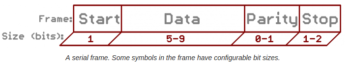
DATA FRAMING & DATA CHUNCK
Data framing generally refers to how data is "packed" to be driven in communication channel and correctly (directionally and entirely) be received.
To do that, it's almost ever required to add an header(start bit) and a tail(stop bit) to say when the chunk (term that indicates no lenght it's up to now precisely defined)
of data begins and finish, in addition also parity bits can be included in the package sometimes.
DATA SYNCHRONIZATION
Now, it comes out another agreement the talking microcontrollers must find: ENDIANNESS of data.
This obscure word simply set if the least- significant bit (LSB) or the most-significant bit (MSB) is sent first.
PARITY BIT
This additional part of data frame, works as low-level checking of data transfer. I feel I couldn't explain it better than with Sparkfun explanation:
"It comes in two flavors: odd or even. To produce the parity bit, all 5-9 bits of the data byte are added up,
and the evenness of the sum decides whether the bit is set or not. For example, assuming parity is set to even and was
being added to a data byte like 0b01011101,
which has an odd number of 1’s (5), the parity bit would be set to 1. Conversely, if the parity mode was set to odd, the parity bit would be 0"
Being additional and slowing transfer a while, it is not used that much.
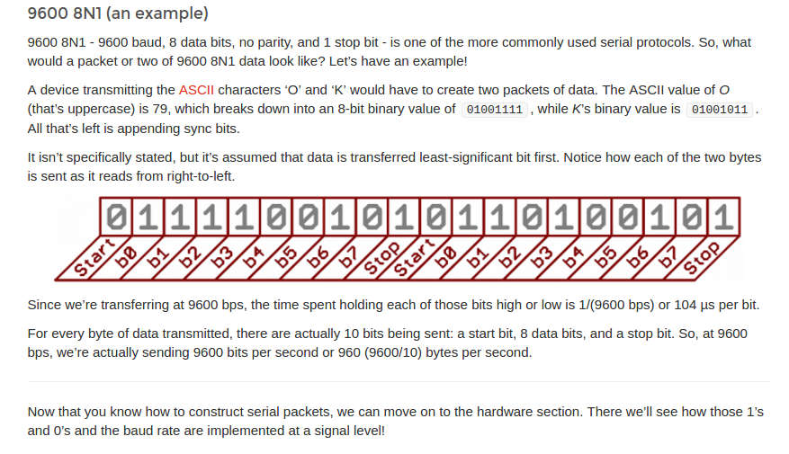
I here report a conventional data framing (9600 8N1) which clearly puts together previous definitions:
HOW IS SERIAL PROTOCOL IMPLEMENTED AT HARDWARE LEVEL
Generally speaking, serial protocol at hardware level can be seen as next image for what regards wiring:
 If data can be sent from both device on the same channel at the same time we talk about full-duplex communication, while if
just a device per time can talk it is called half-duplex.
If data can be sent from both device on the same channel at the same time we talk about full-duplex communication, while if
just a device per time can talk it is called half-duplex.
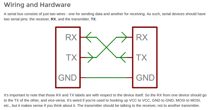
Wiring for serial communication shows up in different ways at hardware interface
and we'll see now that I'll briefly go through main ways of serial asynchronous communication implementations I'm interested in this week.
UART
I found great help in
Make: AVR Programming by Elliot Williams (Chapter 5:"Serial I/O")
at least for what regards UART and USART explanation and initialization.
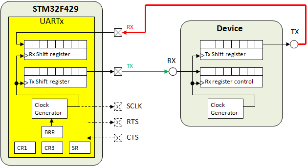
UART and USART idea may be confusing cause we refer to it both to indicate stand-alone ICs whose circuitry is responsible for implementing serial communication (both for sending and receiving) once connected to a board, but also this name refers to microcontroller's built-in peripherals (from datasheets you can see if your microcontroller none, one or multiple UART). In the second case, initializing serial communication results to be UART's register bit-value shifting as it was for I/O programming more or less:
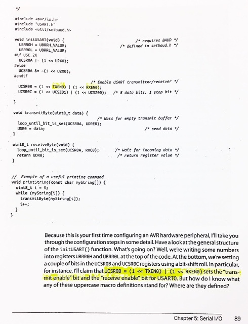
Another idea is to include UART.h library in your code and use initUART function.
Actually previous codes are for USART initialization but it's really close to what I was referring to; I felt quite free to shift a bit
among USART and UART definition:
 Explanation with an intuitive example:
 Our main interest stays in the fact that USART and UART work like serial-to-parallel communication translators.
As explained here, a Universal
(Synchronous-)Asynchronous Receiver/Transmitter:
Our main interest stays in the fact that USART and UART work like serial-to-parallel communication translators.
As explained here, a Universal
(Synchronous-)Asynchronous Receiver/Transmitter:
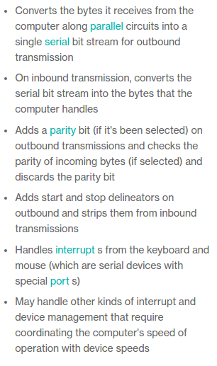 Some of them also have buffer memory to store temporarily data into.
SPI: Serial Peripheral Interface
To have a better idea of this serial protocol implementation, I mostly relied on Elliot Williams' book (Chapter 16)
but also Sparkfun tutorial is really nice and clearly written.
Main characteristics:
- SPI is fast and better suited for small number of devices connections;
- Receiving and Transfer of data have 2 different wires entirely dedicated
- Differently from UART, it is a synchronous protocol: with SPI third wire is entirely dedicated to clock synchronization and you don't have to worry about baud rate each time you send data, but you just have to decide first which voltage data would be read with before communicating
- There's almost no overhead in data framing so communication is faster (remember with UART -9600 8N1- 10 signals were required to send 8 bit); this function would be submitted to a fourth wire
Now, just two words about clock: as said, it is constantly kept sync but actually it is generated from one of the devices in communication, the one identified as master
who sends clock signal in SCK channel so as that all devices can set voltages used by MOSI (Master-Out Slave-In) and MISO (Master-In Slave-Out).
Arrows in the scheme of the picture above help a lot in understanding data flows and also descriptions given clarify ideas pretty well:
Last phrase is quite important: MASTER and SLAVE can do same things, their conventionally sad names just wants to define who sets clock for who.
In addition, differently from UART, both master and slave can receive and transmit at same clock tick on their respective (MOSI and MISO for transmitting, MISO and MOSI for receiving) lines, we so have truly full-duplex communications
Let's now go just a little bit deeper into...
...talking to sensors
Imagine to have a board (the master) onto which there's a LED you want to light up once another board (the slave)'s temperature sensor sees there are more than 23°C.
To receive data from the sensor, the master MUST send some (any) data first, which is actually ignored from the sensor but necessary for clock setting of slave board.
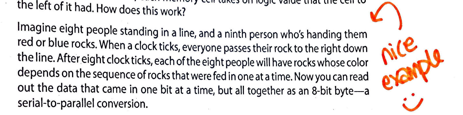
...serial-to-parallel convertion of data
Now, this topic's quite nasty but I just wanted quick understanding of what does go on into microcontrollers while such a fast process is going on.
According to the fact that CPUs work with bytes, there's an urge to re-assemble bits that are one by one sent at clock ticks: we need to pass from serial to parallel
data again. I understood there's a mystic entity into the microcontroller that allows us to put 8-wires connection a part (parallel communication-see above) and slim it
down to MOSI, MISO, SCK and SS wires: the shift registers. Those divine intangible presences can also work the other way up once it regards data sending but, since I really
little understood how they worked, I just got satisfied with this example:
I2C
Once you read well about SPI protocol, it shouldn't be that hard to move up to I2C.
Differences & Equalities with SPI:
- with I2C it is possible to manage up to 128 devices at a slower speed than SPI one
- each device can be given an address to be used in data package as prefix so as to send messages to the right addressee - this function was held by SS wires in SPI (didn't hear about it? see in the image above)
- it uses the minimum number of wires (just 2 for data and one for ground) but it thus give just half-duplex communication facilities
- I2C is a bit more complicated from user's standpoint
- I2C is synchronous protocol like SPI: master node is still charged to send out timing signal
Listed main differences, let's now see working features of I2C, also known as TWI or I2C -different names found their origin in escaping from
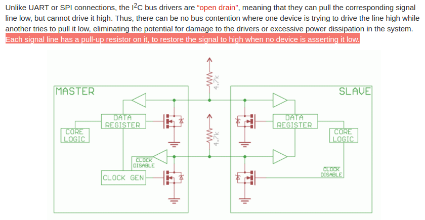
licensing issues. We said we have a line for data, which is called SDA, one for clock signal SCL and one that grounds the connection. Focusing on first
two, as always they both can assume just 1 or 0 values and in particular data line (SDA) can change its values only when SCL is low (0). With two exceptions:
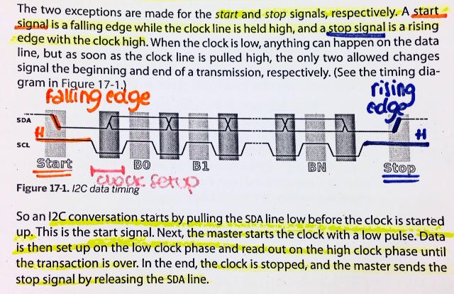
ADDRESSING SCHEME
As said before, each slave is identified by and address so that it can understand when it's being talked to. The most common way is giving 7-bit addres + 1 extra bit
which is required for read/write definition: is master wants to read from slave, the extra bit would be set high, if it wants to read from it would be low.
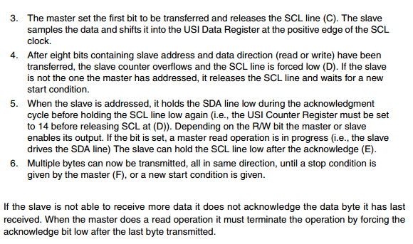
RECEIVING ACKNOWLEDGING
In I2C protocol, whoever is receiving something, it has to tell the sender if data have been correctly received or not. This, at bit level it is done by
adding a ninth bit after 8-bit data, a zero (ACK) tells the sender the byte has been received correctly and to continue sending, a one (NACK) warns there has been
an error and sender should stop sending data or it says the communication is going to end.
Code Writing
In code writing I considered working for my final project and making microphone board and
Braino
communicate but, since no one of my mates was working with SPI protocol. I preferred to started with I2C
protocol with the first intention to make Arduino and my
hello board
talk to each other, where Arduino would have be the master that sent a signal to the slave hello board to make the LED blink
To do that, Simone helped me a
lot in Arduino's Wire library
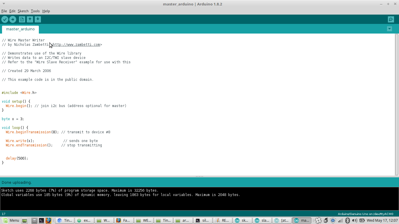
understanding. We together had a look to each function description and step by step analysed and rewrote it:
here Master Writer code source.
After some changes my master code (WORKING MASTER CODElooked like this:
TWI
It looked quite simple with someone else's help, but things would have got harder for Hello board (which was my case's slave) since Wire
library can't be used for Attiny44.
In its place TinyWireS library is used instead, because Wire library is too big to run onto Attiny44:
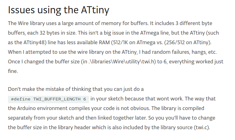
NB:"S" stays for slave :) for master functions look for TinyWireM.
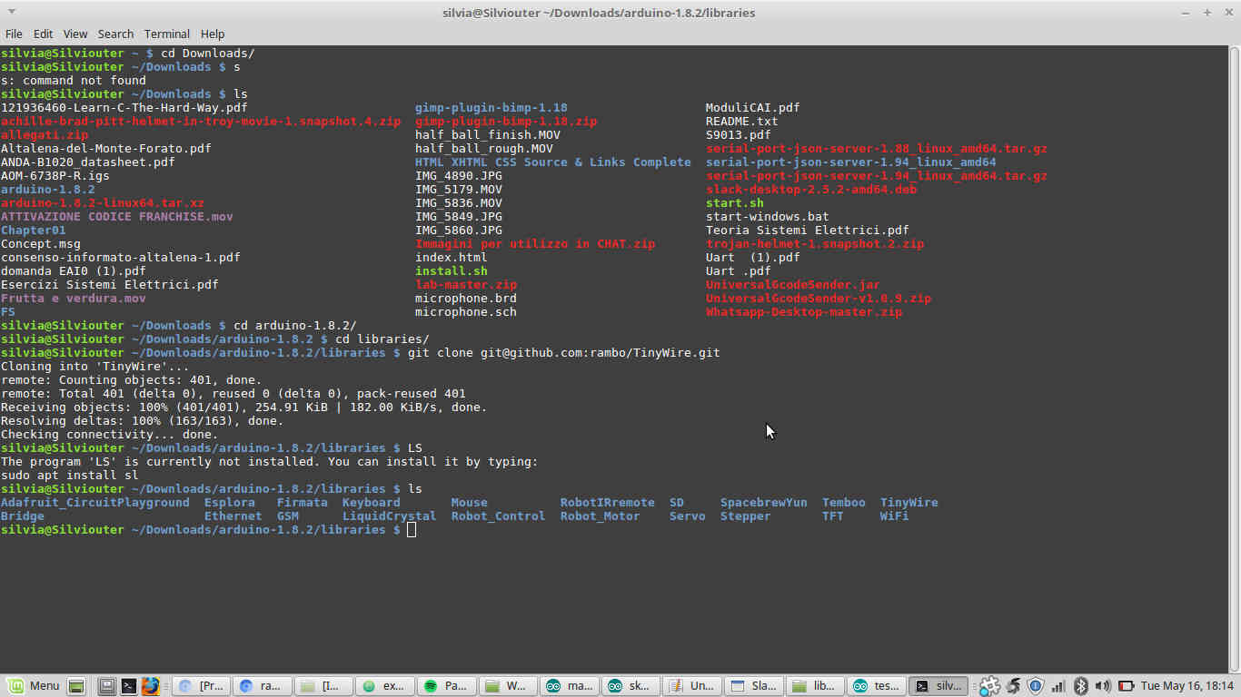
I moved into arduino's folder from shell and ran git clone SSHkey command:
 Now that this administrative issue had been performed successfully, I realized I needed a minimal understanding
of what TWI was. I therefore scrolled ATtiny44 datasheet:
Now that this administrative issue had been performed successfully, I realized I needed a minimal understanding
of what TWI was. I therefore scrolled ATtiny44 datasheet:
 I found this example of slave code for a LED-provided
board (actually two LED are working in the code).
I found this example of slave code for a LED-provided
board (actually two LED are working in the code).
I then tried to edit the code to make it suitable for my case. I therefore changed:
SLAVE CODE
- slave address - defined in master code
- output pin for LED - check ATtiny44 Arduino pinout
- I deleted functions related to LED2 - I just had an LED on hello board
- I substituted Blink function defined in the example with basic digitalWrite and delay cause I didn't feel much confident
DON'T USE FOLLOWING CODE
As soon as I clicked on Verify button, I got a little bunch of errors:
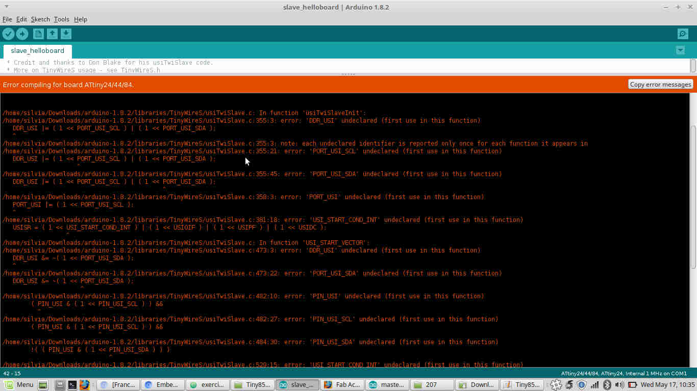 What the evil did I write??? Before debugging my code I tested example's one firsta nd I received same errors by clicking on Verify
even when simply copying and pasting code.
What the evil did I write??? Before debugging my code I tested example's one firsta nd I received same errors by clicking on Verify
even when simply copying and pasting code.
So there must be something wrong in the library I included (which was the .zip one), that was not the one I added into arduino/libraries.
I tried to:
- Substitute library into arduino/libraries ERROR: INVALID LIBRARY
- After Ctrl+Z of previous situation was done, I tried to copy and paste my slave_helloboard.ino's folder into arduino's one ERROR: TinyWireS.h no such file or directory
- I deleted and re-cloned TinyWire library SAME ERROR:
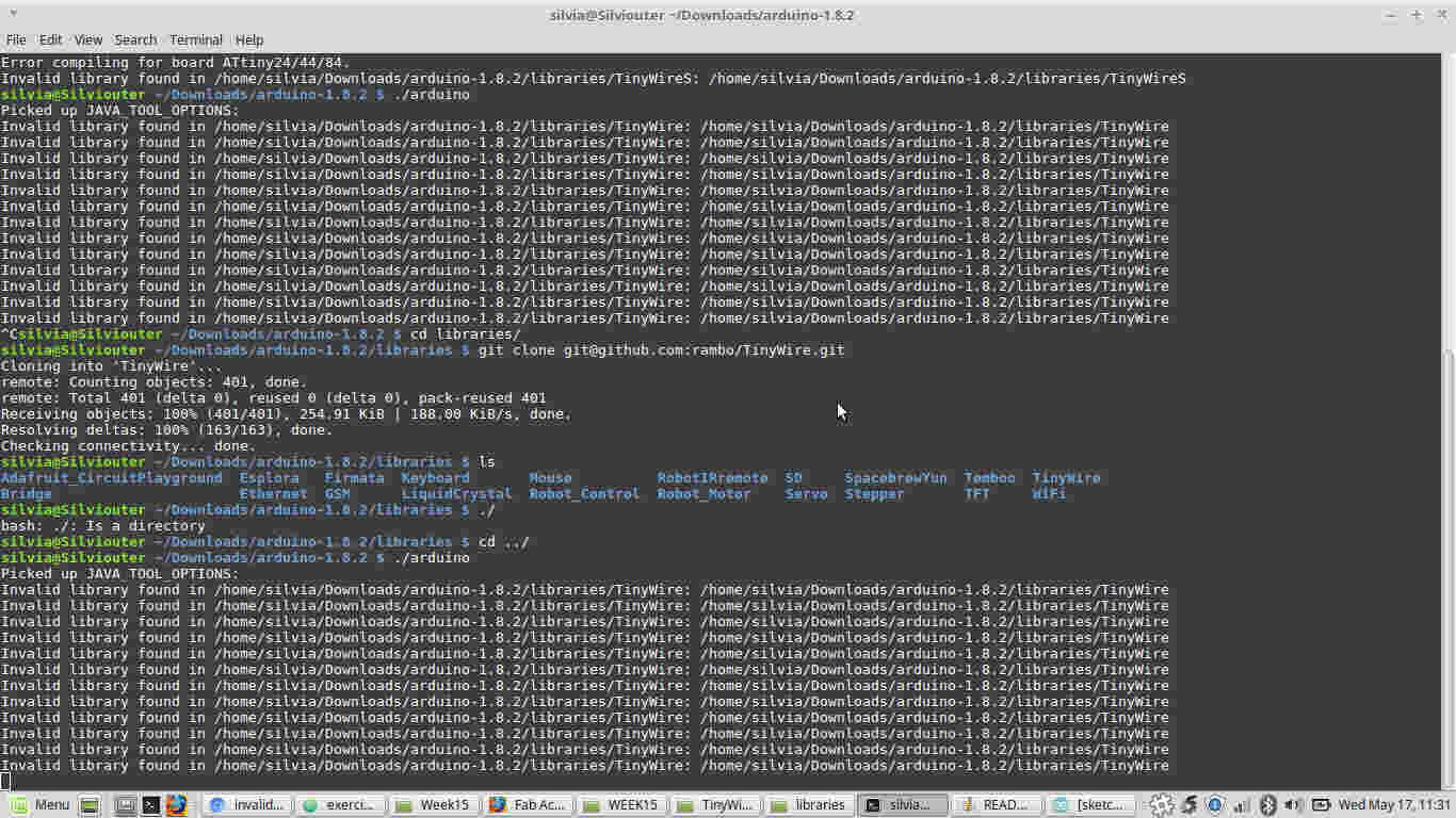 After asking my friend Simone where the problem may come from,
we soon realised it was due to library inclusion done with " " instead of < > and wrong settings in Tools-->Board (which had to be Attiny44), Tools-->Port and Tools-->Clock (external 20MHz - I had a resonator on the hello board).So...
After asking my friend Simone where the problem may come from,
we soon realised it was due to library inclusion done with " " instead of < > and wrong settings in Tools-->Board (which had to be Attiny44), Tools-->Port and Tools-->Clock (external 20MHz - I had a resonator on the hello board).So...
Silvia but I still hadn't connect the board to the USB port.Why should I do that? You needn't connect it up to this point but it's because some
TinyWire library version are intended not for all AVR microcontrollers and this would help you in seeing if you cloned the right version into arduino/libraries.
By the way, correct (I hoped) code I used in first test was the following:
I so connected my hello board to the ISP to USB port (check right connection between hello board and FabISP carefully) and uploaded the sketch:
 I disconnected FabISP and connected Arduino UNO to USB port and, after setting right board (Tools-->Board) I compiled master code:
Let the wiring party start!
I was now ready to connect Arduino and Hello board.
Since Arduino would be my master, it had to be connected to USB port and beside SDA and SCL pins I had to connect also 5V and GND pins of Arduino to hello board ones
so as to give power also to the second board.
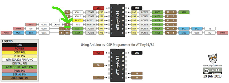
I therefore checked which AVRISP pin I needed using hello board schematic...
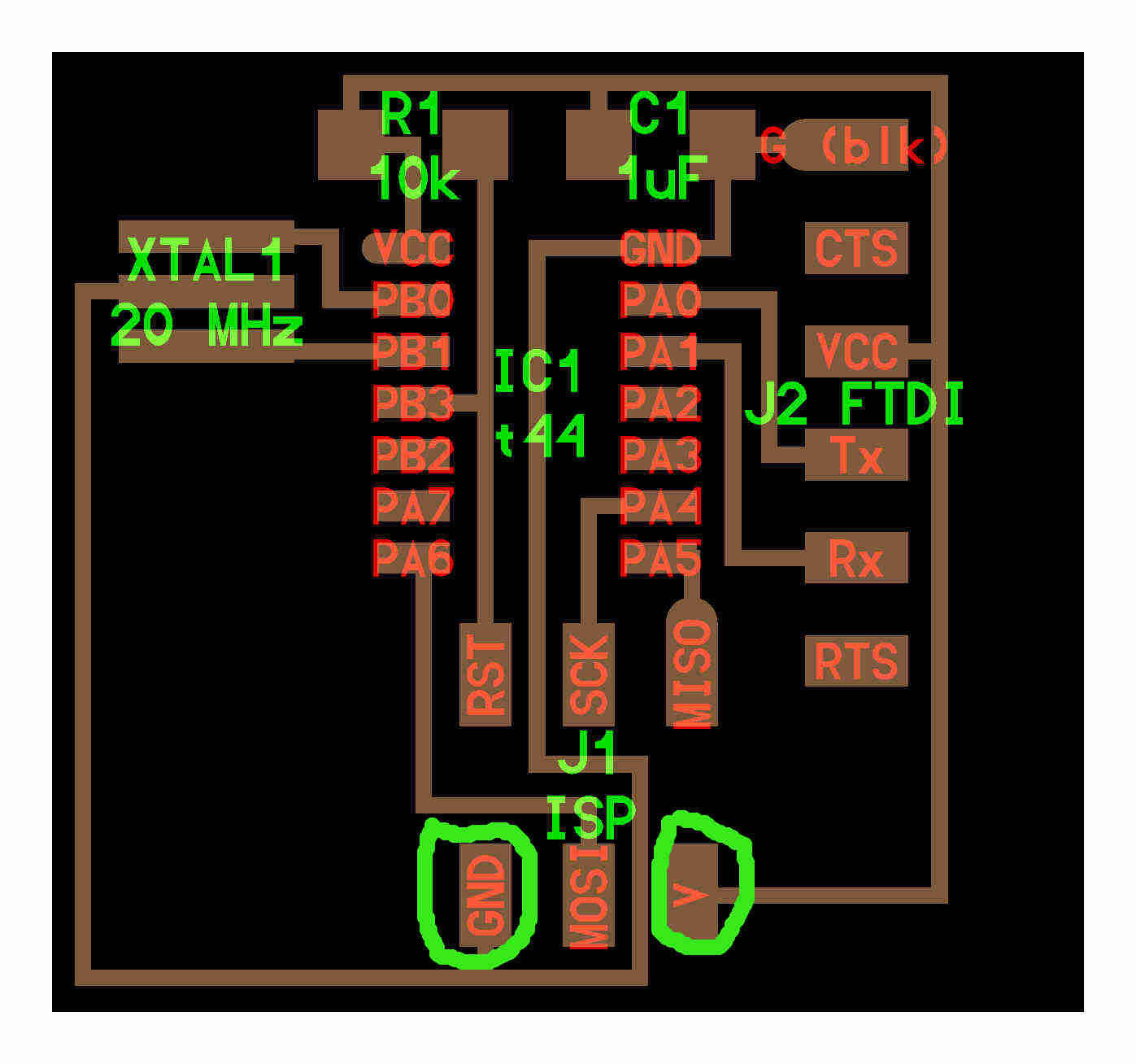 ...and attiny44 pinout
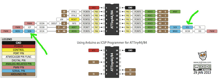
.jpg) And, for Arduino UNO:
And, for Arduino UNO:
 I double-checked connections between boards, connected arduino to USB port, but nothing worked.
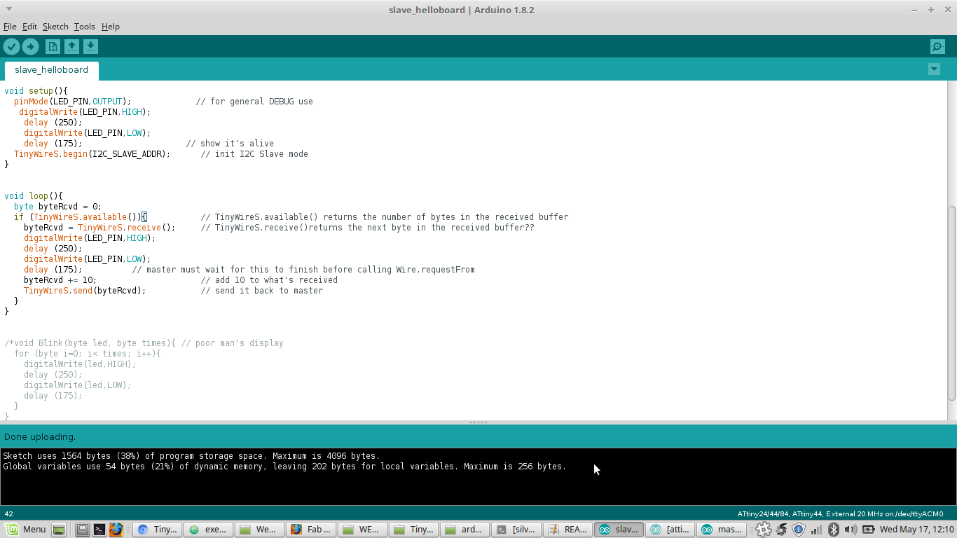
LED pin debugging
I was previously doubtful about pin number I used in slave code and I tried to change it:
WORKING SLAVE CODE
 I then re-compiled it using FabISP, then I reconnected it to Arduino and everything worked!! :)
ArduinoUno talking to HelloBoard from Silvia Palazzi on Vimeo.
Update 2nd July 2017 - Braino as slave and Final Project's board as master
I tried to repeat serial communication experiment with two board I made: this time I wanted my
Braino
(slave) send 1 or 0 random
to my final project's board (master),
which, according to the value received would turn on a led for 3 seconds or blink it twice.
The two boards I decided to use both contain ATtiny44 microcontrollers and have many exposed pins; in particular, Braino is also provided with minimal circuit needed to drive a
vibration motor (diode, mosfet...) but no external 20MHz resonator and both boards have external pull-up resistors.
The main difference with previous example was that I had to use TinyWireM
library. In fact, boards that have Attiny microcontrollers on
can't contain Wire.h library because it's too big (as said). So now it was time to download and put into arduino/libraries/ folder also
TinyWireM library.
I wrote the following codes:
MASTER
SLAVE:
When I uploaded slave and master codes on the boards they were intended to be for, at first nothing worked because in master code I wrote got == '1' and
got == '0', but even after fixing that, the behaviour I got was like the master was getting only 1 values (which sounded not that random to me):
I then had a deeper look at random function I used in slave's code and the problem came out:
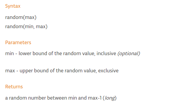 In fact, since I wrote random(0,1) the only value the function generated was 0. I then edited the code changing with
 radom(0,2):
Since I gain same behaviour, I continued debugging my code and reading from TinyWireM docu, I realized this library is set to run at 1 MHz.
So since now onward, I payed attention in setting the right clock (going through Tools-->Clock) both for master and slave (even if master board has an external clock,
SCL has to be set equally from both boards in order to have a time-correct communication otherwise LED could blink longer/shorter and also debugging
would become a bigger challenge) before uploading a code.
Anyway, when I connected the two boards, it was like the master only received 0 value.
Feeling that it may depend on random function, I decided to see if by me deciding to send just 1 or 0 (on the slave code, the master one didn't change), I gained the behaviour I wanted:
SENDING 1:
code
behaviour
I think I have to fix a bit clock synch so as to make the LED blinking effectively for 1000 or 800 or whatever longer time.
SENDING 0:
code
behaviour
So, owing to this result, I saw that the communication worked between the two boards if sending just a value (even with some clock debugging to be done), but random function didn't.
I then tried to change a bit my code, so as not to leave the value sents to chance, but making them change with cyclic nature. In the setup, I also set
SDA(pin) and SCL(pin) internal pullup, since I2C protocol requires it (and my Braino doesn't have an external one):
 code:
code:
Bluetooth communication
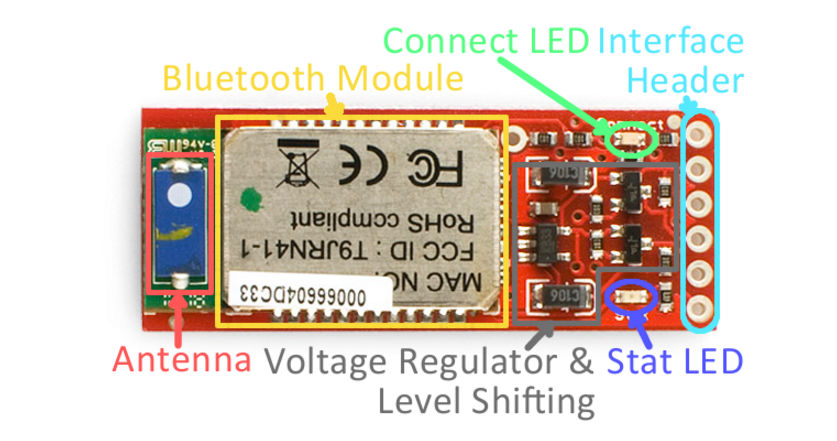
Quick overview about Bluetooth module (I took Sparkfun's Silver Mate as an example)
 I can't say Bluetooth is easy to be used but I found HUGE help in this tutorial.
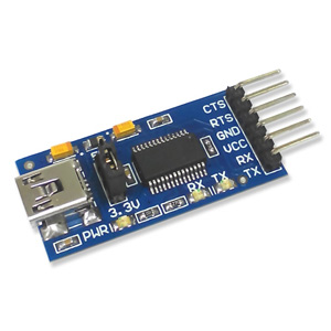
What you essentially have to know before starting with FTDI cables, serial monitor and AT commands (I was like WHAAAAAAAAAAAT!?!?!? at first too, don't worry) is that
there are two roles in Bluetooth modules communication: master and slave.
The master creates the communication channel to which the slave connects later on, then both modules can send and/or receive data.
Now, at hardware level, there are two types of Bluetooth modules: HC-05 and HC-06.
The first can be both a master or a slave while the second can only assume slave function.
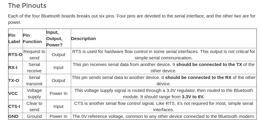
BT modules are provided with header that you would link to your board's microcontroller pins like this:
| Module's pins | Board's pins |
|---|---|
| GND | GND |
| VCC | VCC |
| RXD | TX |
| TXD | RX |
So basically you have to pay attention in inverting the receiving and transmitting line otherwse it won't work.
Then, the first thing to do is to configure the modules. To do that I used an Arduino UNO and I wired it to the module like shown in table (TXD of module with Arduino's RX and viceversa for RXD).
An important thing to do is to understand how to access AT mode, so as to send AT commands on serial monitor from the Arduino IDE: some modules are provided with a button to do that and you simply have to start pressing the button when
the module is getting power, removing VCC wiring while still pressing, reconnect it and only after leave the button, others require using a cable connected to a 3.3V source. How do I see if I enetered AT mode?
The LED on the module while stay on a little bit longer than usual and then change (slow down) blinking rythm.
Notice that AT command can be sent on serial monitor only at 38400 baudrate.
The code you have to upload onto your Arduino UNO is the following:
NB:for other Arduino Mega it would be different
Then, from serial monitor (after double checking AT mode is on) you have to send the following commands:
AT and the answer will be OK;
AT + cmode = 1 and the answer will again be OK;
AT + role = 1 so as to set the module your are working on as master (the value will be 0 to set as a slave; to ask how the module is now set, use AT + role? command) and the answer will again be OK;
AT + init to initialize devices research and the answer will be OK;
AT + inq to search for close devices and the answer will be the address of the device,like +inq:4D65:4D:CA6612,5A0204,7FFF and immediately after that another OK (if the device is already known, the module will NOW connect to it);
AT + bind = (connected bluetooth address) and OK again;
AT + pair = (address of the module you're going to be connected to) you are connecting to the module and if it goes well you get another OK.
Up to this point, you connected two Bluetooth modules and if you write something on one's serial monitor, the other will receive it.
For further exploitation about Bluetooth's AT commands, I'm still a beginner to help you, but we can spend two words on the library you need to include into your code and its main functions.
The one I used up to now is simply SoftwareSerial.h library, since with AVR microcontrollers like ATtiny44 and ATtiny45, having no RX and TX pin defined, you have to simulate receiving and transmitting functions on two
analog pins. Consequently, sending data would reveal to be a Serial.write function, while reading will be Serial.read.
Let's by now take a code I wrote for my final project:
What I do in the upper part is to define, the motor (output) pin, a variable (c) and my TX and RX pin - to know who they are, take your board, look at FTDI headers
and the one that goes to FTDI's RX will be your txpin and viceversa for TX and rxpin. Then I defined a virtual serial port with a class which I named "bluetooth", to set its baudrate in setup oart of the code.
Then, in the loop, I wrote classname.available to see if the BT is receiving data or not and if it does, I want them to be written in the variable.Serial.write function then gives me feedback on the serial
monitor about those values and if they are more than a certain value (10 in my case), a motor will vibrate.
Conclusions
This week's assignment was quite hard but I found it entertaining somehow. Still, I haven't reached my aim (make the board I would need for my final project talk to each other) and I got little blinking results but a deep diving into serial communication protocol (which covered really big part of my week) teached me lots of things I didn't know and that I hope I'll explore more in practice soon. Also, a future scope is to make more boards talk to each other and to go further than serial world and little of BT one to discover other kind of communications like Wifi.
Download
- MASTER ARDUINO - SLAVE HELLO BOARD