Exercise 10: Output Devices
Assignment 10: Add an output device to a microcontroller board you have designed and program it to do something.
I made this assignment two times, one before and one after Input Devices assignment. Infact the first time I made a very simple board with some Led, so I decided to make again the board using a servo motor. Furthermore I programmed using Make File for the first and IDE for the second board. I starded from the Hello Board both times.
Output one: Led and resistors.
Drawing, milling and soldering the board
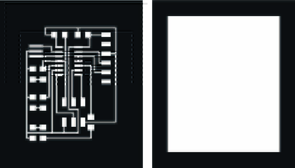
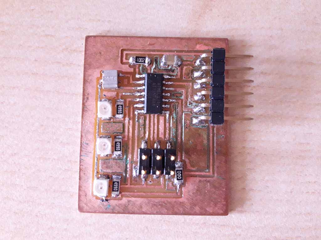
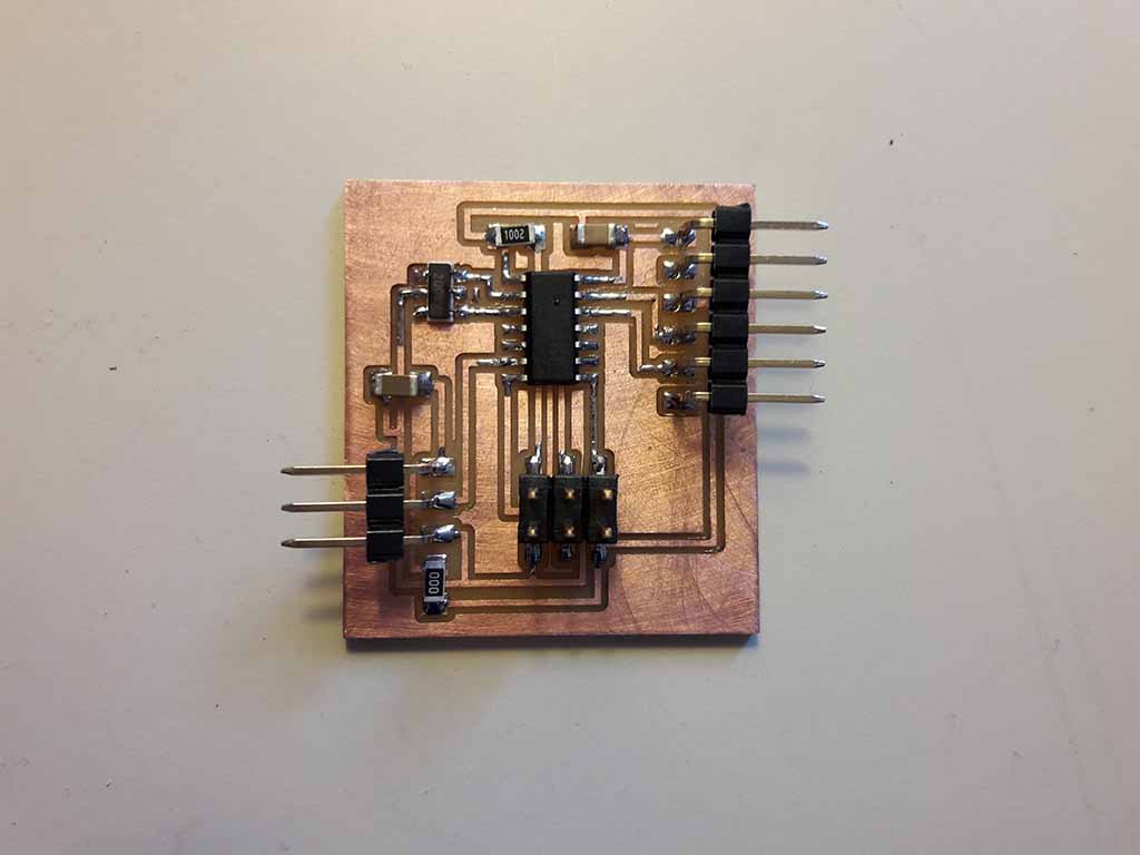
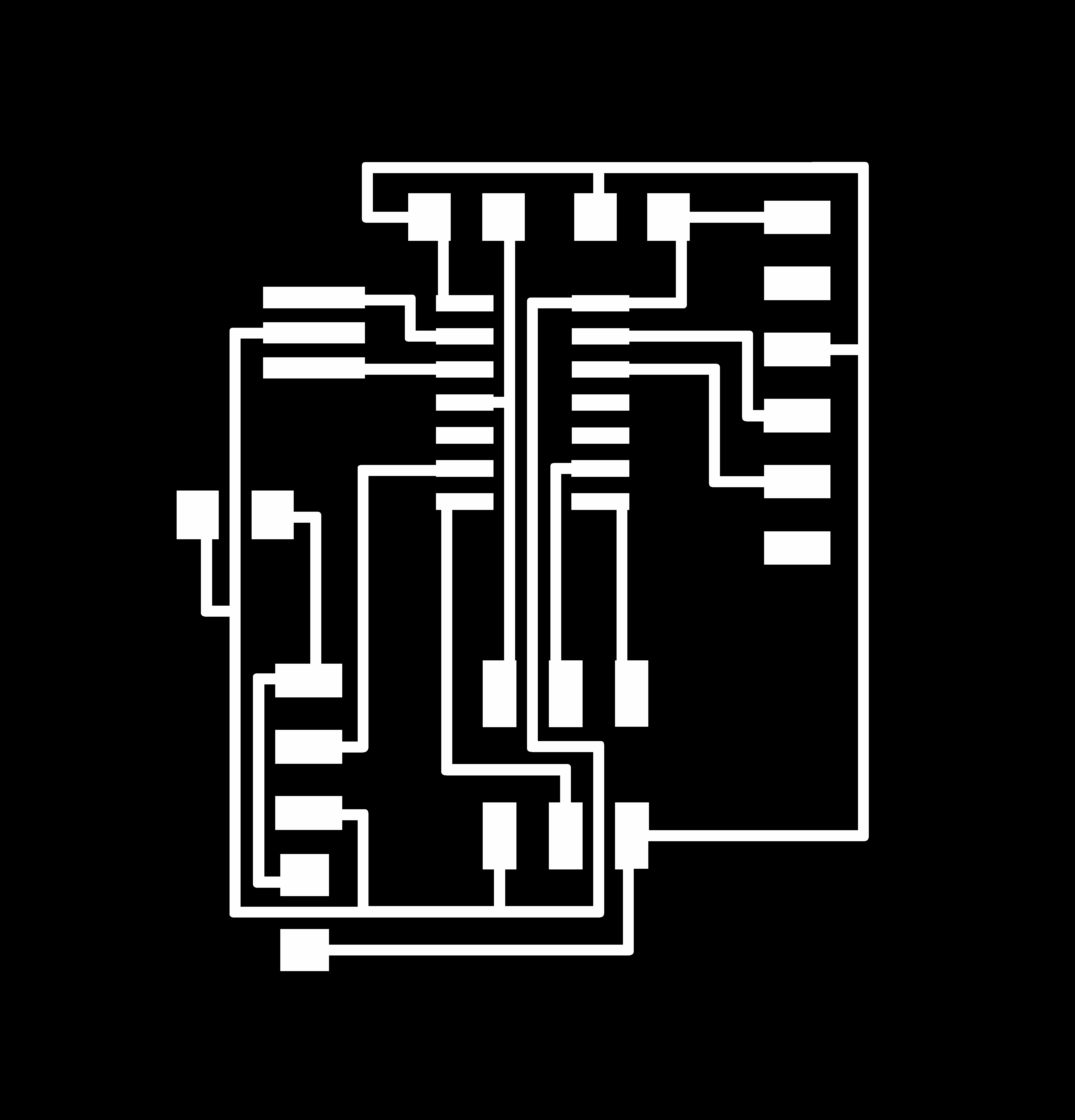
I decided to start using three Led and I draw the board with Eagle starting from the Hello. Below the PNG that I milled (Fig. 1). I had not problem using the milling machine, but when I was soldering I made two errors: I soldered the Led and the microcontroller overturned. Also I made a mistake in circuit design by connecting the Led to the reset pin (I made again the schematic Eagle file after correcting this Pins error and you can dowload it at the end of the page). Maybe I was a little distracted! Next time I will be more careful! I made the soldering again shooting microcontroller and Led. The I eliminated the resistor connected to the reset pin. You can see the result below (Fig. 2).
Programming the board
First of all I setted the Fuses writing on the terminal:
avrdude -p t44 -P usb -c usbtiny -U lfuse:w:0x5E:m
The setting was good and the terminal returned:
    avrdude: AVR device initialized and ready to accept instructions

    Reading | ################################################## | 100% 0.00s

    avrdude: Device signature = 0x1e9207 (probably t44)
    avrdude: reading input file "0x5E"
    avrdude: writing lfuse (1 bytes):

    Writing | ################################################## | 100% 0.01s

    avrdude: 1 bytes of lfuse written
    avrdude: verifying lfuse memory against 0x5E:
    avrdude: load data lfuse data from input file 0x5E:
    avrdude: input file 0x5E contains 1 bytes
    avrdude: reading on-chip lfuse data:

    Reading | ################################################## | 100% 0.00s

    avrdude: verifying ...
    avrdude: 1 bytes of lfuse verified

    avrdude: safemode: Fuses OK (E:FF, H:DF, L:5E)

    avrdude done.  Thank you.
When I tried to programm the board, I had troubles blinking the first LED. As I explaned in week 8, I attached it to the PB3 reset Pin and this is not correct. So I desoldered the first LED and used only the remaining two.
I wrote this code to program the board:
    #include
    #include
    #include

    #define F_CPU 20000000UL        /* 20MHz crystal oscillator */

    #define LEDB_PORT PORTB          /* PORTx - register for LED output */
    #define LEDB_BIT PB2				/* bit for button input/output */
    #define LEDB_DDR DDRB            /* LED data direction register */

    #define LEDA_PORT PORTA          /* PORTx - register for LED output */
    #define LEDA_BIT PA3				/* bit for button input/output */
    #define LEDA_DDR DDRA            /* LED data direction register */


    #define BLINK_TIME 1000/8     		/* time to wait after a button press */

    int main(void)
    {
    LEDB_DDR = _BV(LEDB_BIT);
    LEDB_PORT &= _BV(LEDB_BIT);

    LEDA_DDR = _BV(LEDA_BIT);
    LEDA_PORT &= _BV(LEDA_BIT);


    while (1) {
    LEDB_PORT |= _BV(LEDB_BIT);
	_delay_ms(BLINK_TIME);
	LEDB_PORT ^= _BV(LEDB_BIT);
    _delay_ms(BLINK_TIME);
	LEDB_PORT |= _BV(LEDB_BIT);
	_delay_ms(BLINK_TIME);
	LEDB_PORT ^= _BV(LEDB_BIT);
    _delay_ms(BLINK_TIME);
	LEDA_PORT |= _BV(LEDA_BIT);
	_delay_ms(BLINK_TIME);
	LEDA_PORT ^= _BV(LEDA_BIT);
	_delay_ms(BLINK_TIME);
    }
    }
I wrote this code to program the board and each Led turns on:
Output two: Servo motors.
Drawing, milling and soldering the board
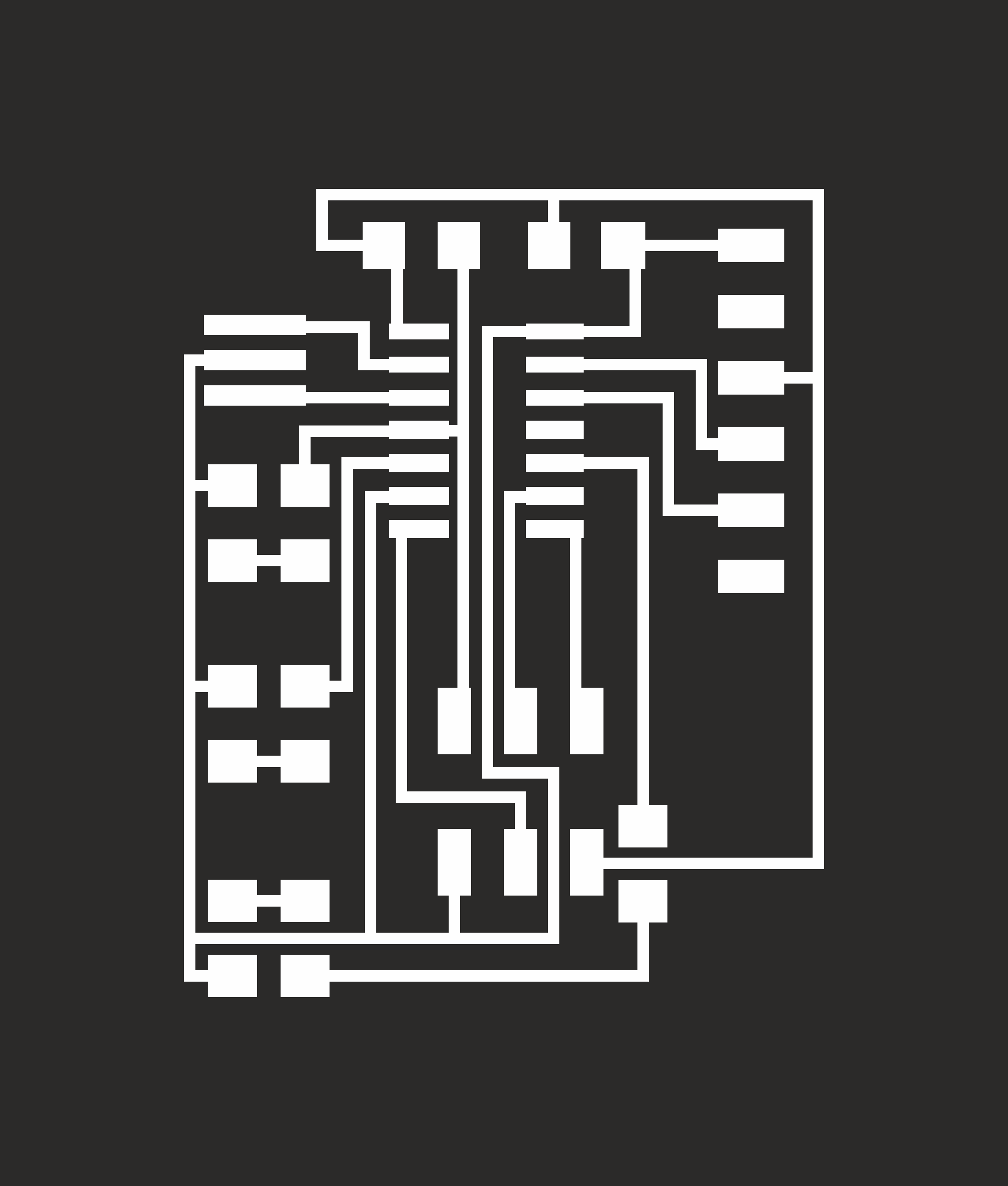
When I finished Input Devices, I decided to return on Output and to make another board using IDE to programm it. This time I used a servo motor! I stated from the hello board and I added a capacitor and pins to connect the servo motor. I milled and soldered it as usual. As with the first board I set the fuses.

Programming the board
I wrote this code to program the board using Arduino IDE.
    #include

    Servo myServo;

    void setup() {
    myServo.attach(PIN_A7);
    }

    void loop() {
    myServo.write(0);
    delay(1000);
    myServo.write(90);
    delay(1000);
    myServo.write(170);
    delay(1000);
    myServo.write(90);
    delay(1000);
    }
Loaded the code, the Motors started to rotate according to the programmed angles. The theoretical servo movement is limited between 0 and 180 degrees, but when I set 180 degrees I saw that it strained, so I set the range between 0 and 170 degrees.
As it worked, I tried to control the movement remotely. But, as explained in this tutorial, hardware serial is not available for ATtiny 44. The default configuration uses AIN0 for TX and AIN1 for RX. Because my board uses Pin A0 and A1 instead for the serial connection to the FTDI, I had to configure SotwareSerial at the beginning of the code.
    #include
    #include

    Servo myServo;
    SoftwareSerial mySerial(PIN_A0, PIN_A1);
    int angolo = 0;

    void setup() {
    myServo.attach(PIN_A7);
    mySerial.begin(9600);
    myServo.write(angolo);
    }

    void loop() {
    if (mySerial.available() > 0) {
    mySerial.read();
    angolo = (angolo + 10) % 180 ;
    myServo.write(angolo);
    }

    }
The program reads the serial port and, when there are data available, moves the Servo by 10 degrees for each character. I used the Modulo division which resets the value to 0 when the angle rreaches the maximum.
Download area
Download my schematic Eagle file for Led Output
Download my board Eagle file for Led Output
Download my edited schematic Eagle file for Led Output with correct Pins
Download my .png file for the Led Output traces
Download my .png file for the Led Output edge
Download my file for milling the Led Output traces with Roland MDX-40
Download my file for milling the Led Output edge with Roland MDX-40
Download the Makefile for Led Output
Download my schematic Eagle file for Servo Motors Output
Download my board Eagle file for Servo Motors Output
Download my .png file for the Servo Output traces
Download my .png file for the Servo Output edge
Download my file for milling the Servo Motors Output traces with Roland MDX-40
Download my file for milling the Servo Motors Output edge with Roland MDX-40
Download the code for the first version Servo Motors Output
Download the code for the second version Servo Motors Output