Exercise 8: Embedded programming
Assignment 8: Read a microcontroller data sheet, program the board to do something, with as many different programming languages and programming environments as possible.
How to program and connect the Hello Board to the PC
The first program I uploaded on the board was the hello.ftdi program provided by Neil. It is a simple echo program plus a Makefile:
I followed these steps to connect:
- the Fab ISP to the computer with an USB;
- the Fab ISP to the Hello Board using a SPI;
- the GND and VCC pins of the Hello board to GND and 5V;
- run the makefile.
I followed the instructions posted here in order to compile and upload the code from Ubuntu Linux:
    $ make -f hello.ftdi.44.echo.c.make
    avr-gcc -mmcu=attiny44 -Wall -Os -DF_CPU=20000000 -I./ -o hello.ftdi.44.echo.out hello.ftdi.44.echo.c
    avr-objcopy -O ihex hello.ftdi.44.echo.out hello.ftdi.44.echo.c.hex;\
    avr-size --mcu=attiny44 --format=avr hello.ftdi.44.echo.out
    AVR Memory Usage
    ----------------
    Device: attiny44

    Program:     760 bytes (18.6% Full)
    (.text + .data + .bootloader)

    Data:         64 bytes (25.0% Full)
    (.data + .bss + .noinit)


    $make -f hello.ftdi.44.echo.c.make program-usbtiny-fuses
    avr-objcopy -O ihex hello.ftdi.44.echo.out hello.ftdi.44.echo.c.hex;\
    avr-size --mcu=attiny44 --format=avr hello.ftdi.44.echo.out
    AVR Memory Usage
    ----------------
    Device: attiny44

    Program:     760 bytes (18.6% Full)
    (.text + .data + .bootloader)

    Data:         64 bytes (25.0% Full)
    (.data + .bss + .noinit)


    avrdude -p t44 -P usb -c usbtiny -U lfuse:w:0x5E:m

    avrdude: AVR device initialized and ready to accept instructions

    Reading | ################################################## | 100% 0.00s

    avrdude: Device signature = 0x1e9207 (probably t44)
    avrdude: reading input file "0x5E"
    avrdude: writing lfuse (1 bytes):

    Writing | ################################################## | 100% 0.00s

    avrdude: 1 bytes of lfuse written
    avrdude: verifying lfuse memory against 0x5E:
    avrdude: load data lfuse data from input file 0x5E:
    avrdude: input file 0x5E contains 1 bytes
    avrdude: reading on-chip lfuse data:

    Reading | ################################################## | 100% 0.00s

    avrdude: verifying ...
    avrdude: 1 bytes of lfuse verified

    avrdude: safemode: Fuses OK (E:FF, H:DF, L:5E)

    avrdude done.  Thank you.

    $ make -f hello.ftdi.44.echo.c.make program-usbtiny
    avr-objcopy -O ihex hello.ftdi.44.echo.out hello.ftdi.44.echo.c.hex;\
    avr-size --mcu=attiny44 --format=avr hello.ftdi.44.echo.out
    AVR Memory Usage
    ----------------
    Device: attiny44

    Program:     760 bytes (18.6% Full)
    (.text + .data + .bootloader)

    Data:         64 bytes (25.0% Full)
    (.data + .bss + .noinit)


    avrdude -p t44 -P usb -c usbtiny -U flash:w:hello.ftdi.44.echo.c.hex

    avrdude: AVR device initialized and ready to accept instructions

    Reading | ################################################## | 100% 0.00s

    avrdude: Device signature = 0x1e9207 (probably t44)
    avrdude: NOTE: "flash" memory has been specified, an erase cycle will be performed
             To disable this feature, specify the -D option.
    avrdude: erasing chip
    avrdude: reading input file "hello.ftdi.44.echo.c.hex"
    avrdude: input file hello.ftdi.44.echo.c.hex auto detected as Intel Hex
    avrdude: writing flash (760 bytes):

    Writing | ################################################## | 100% 0.74s

    avrdude: 760 bytes of flash written
    avrdude: verifying flash memory against hello.ftdi.44.echo.c.hex:
    avrdude: load data flash data from input file hello.ftdi.44.echo.c.hex:
    avrdude: input file hello.ftdi.44.echo.c.hex auto detected as Intel Hex
    avrdude: input file hello.ftdi.44.echo.c.hex contains 760 bytes
    avrdude: reading on-chip flash data:

    Reading | ################################################## | 100% 0.87s

    avrdude: verifying ...
    avrdude: 760 bytes of flash verified

    avrdude: safemode: Fuses OK (E:FF, H:DF, L:5E)

    avrdude done.  Thank you.
Unfortunately, no more ftdi cable were available at OpenDot, so I was not able to test my echo program and check if the program was running correctly on the ATTiny.
C code
Emanuele suggested me to use another program and blink at least the led attached to pin PB2. He pointed me to its week6 assignment, where he reposted a simple C code for blinking a led with an infinite loop.
    cddddz#include <avr/io.h>
    #include <inttypes.h>
    #include <util/delay.h>

    #define F_CPU 20000000UL
    #define LED_PORT PORTB
    #define LED_BIT PB2
    #define LED_DDR DDRB
    #define BLINK_TIME 1000

    int main(void)
    {
    LED_DDR = _BV(LED_BIT);
    LED_PORT |= _BV(LED_BIT);
    while (1) {
	_delay_ms(BLINK_TIME);
    LED_PORT ^= _BV(LED_BIT);
    }
    }
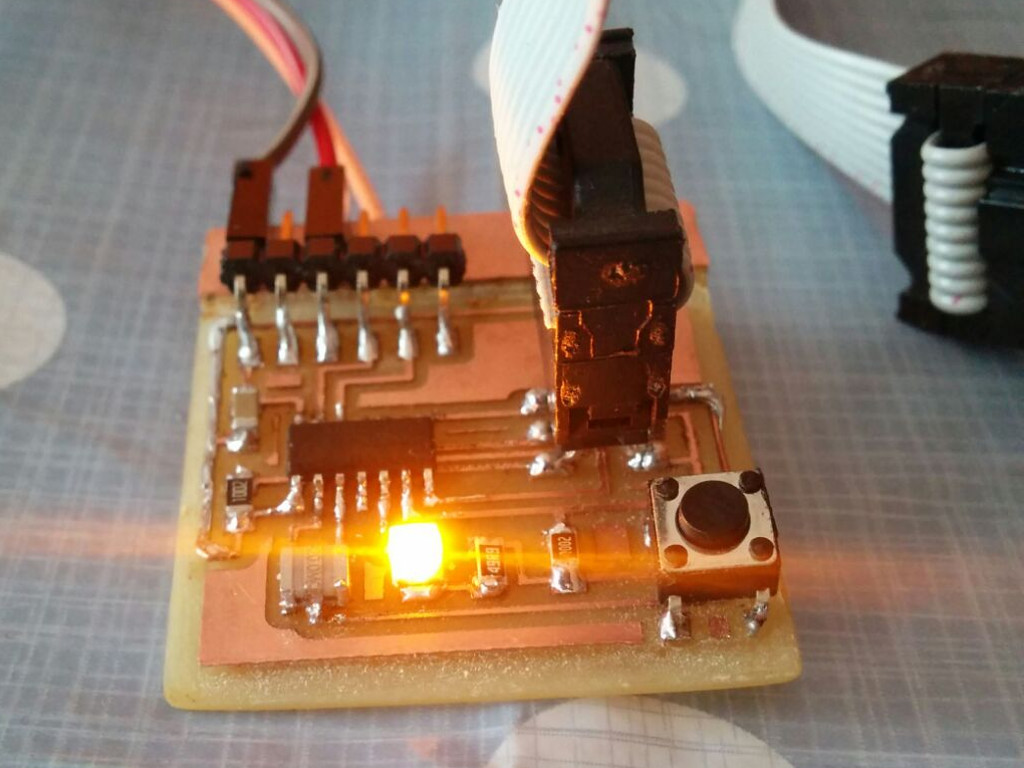
I used the the make file of the hello echo file changing the name of the project in the first line from PROJECT=hello.ftdi.44.echo to PROJECT=blink. Then I run again the commands to make and upload the binary.
And the led started blinking (Fig. 1)!
Arduino Ide
I tryed again to programm the Hello board after using Arduino Ide (see my Input Assignment to know hot the install and use it). i decided to use Led light to send an SOS signal: 3 short lights, 3 long lights, 3 short lights.
I wrote this code:
    void setup() {
    pinMode(PIN_B2, OUTPUT);
    }

    void loop() {

    digitalWrite(PIN_B2, HIGH);
    delay(100);
    digitalWrite(PIN_B2, LOW);
    delay(50);
    digitalWrite(PIN_B2, HIGH);
    delay(100);
    digitalWrite(PIN_B2, LOW);
    delay(50);
    digitalWrite(PIN_B2, HIGH);
    delay(100);
    digitalWrite(PIN_B2, LOW);
    delay(50);

    digitalWrite(PIN_B2, HIGH);
    delay(200);
    digitalWrite(PIN_B2, LOW);
    delay(50);
    digitalWrite(PIN_B2, HIGH);
    delay(200);
    digitalWrite(PIN_B2, LOW);
    delay(50);
    digitalWrite(PIN_B2, HIGH);
    delay(200);
    digitalWrite(PIN_B2, LOW);
    delay(50);

    digitalWrite(PIN_B2, HIGH);
    delay(100);
    digitalWrite(PIN_B2, LOW);
    delay(50);
    digitalWrite(PIN_B2, HIGH);
    delay(100);
    digitalWrite(PIN_B2, LOW);
    delay(50);
    digitalWrite(PIN_B2, HIGH);
    delay(100);
    digitalWrite(PIN_B2, LOW);
    delay(500);
    }
I uploaded it and soon the SOS signal started!
Reading the datasheet
During week 10 I attached an LED plus it's current limiting resistor to PB3. However, I was not able to program the board and Emanuele pointed me back to the datasheet.
So I searched and downloaded the full datasheet of the ATtiny44 from the Microchip website.
Reading carefully the first pages, I discovered that Port B is a 4-bit bi-directional port for Input and Output. However, PB3 is an exception because it has the RESET capability (and I/O and RESET are mutually exclusive operating modes).
To use pin PB3 as an I/O pin, instead of RESET pin, you have to program (‘0’) RSTDISBL fuse. However, setting this fuse disable further programming of the microcontroller.
Hence, I detached the LED and in all future versions of my board based on the ATtiny44 i did not use the PB3 pin for input or output, and I left it attached only to the ICSP programming header.