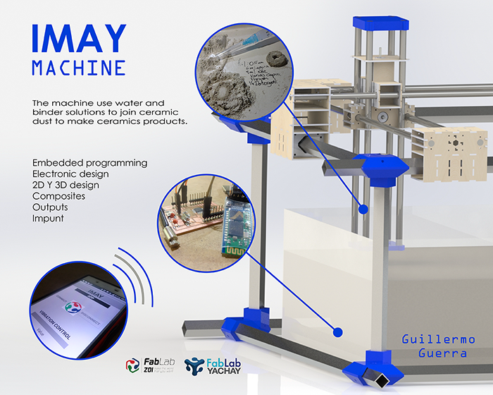
To my finally project, I make a different process to make a prototype faster on ceramic with the precision of a CNC machine.
I explore different options for take a new system of 3D printing in ceramic whit an concept in a machine
in which the size of printing is not a problem very important.
Composites
To do it we take recycling ceramic material plus natural binder. The recycling ceramic material is a compost of two types of ceramic
powder; the first is when you sand the imperfection of the pieces and the second one is the fail pieces that you take of the first burn.
Of the natural binder, we buy this to all production in the ceramic workshop.
Can I make a faster prototype on ceramic?
Is possible to join these materials?
Can I make 3D models using these composites?
Is it possible to exemplify the powder ceramic with natural binder?
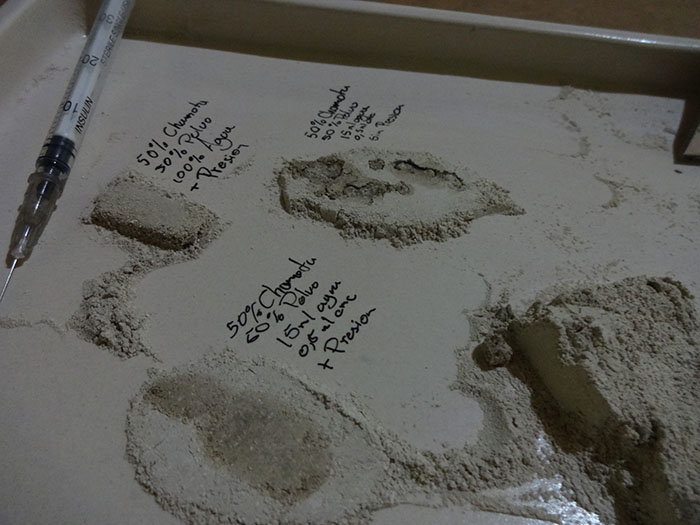
Ceramic Powder + natural binder
In this part experimented check the correct quantity to apply each one of them.
To ceramic powder, I take two different type states of material. The first is
the recollected of sand between take out the mold and the second of fail pieces
in the first burned. This combination add more structure of material.
Carboxymethylcellulose (CMC), Organic compound used as thickener.
To dilute it recommended leaving in water for 2 or 3 days.
To make this test, I take so mix with the different percent of these materials. To generate the proper consistency to
get this y make a different test of ceramic powder and the natural binder.
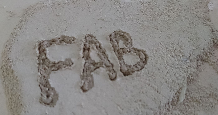
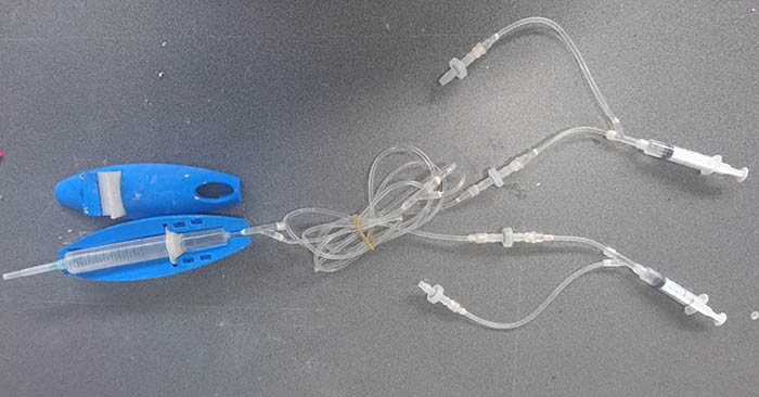
I need generate a material in which I can manipulate to lead on the next process to show the prototype and
I use the mix previously detailed. This mix can take a form in 3D for manipulate and generate a form with
controlled to the hands.
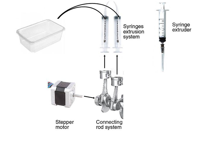
In the next video, I control this movement and the fluid control whit the hands, now automate the process developed by hand.
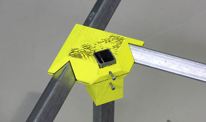
To extract the ceramic piece, I design a component that facilitates the process without damaging the same.
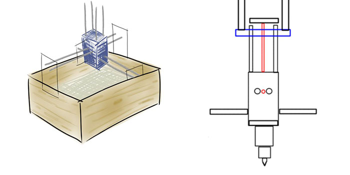
Machine Design
Demonstrate 2D & 3D modelling capabilities applied to your own designs
select and apply appropriate additive techniques
To my final project, I change the design of the machine we make in the assignment “Mechanical” and “Machine Design”,
I take the idea and the design and make changes.
To this part, I use solidworks to make the design and mechanical simulation to different changes to improve the previous
design and to be able to couple the different mechanisms of each member with his project.
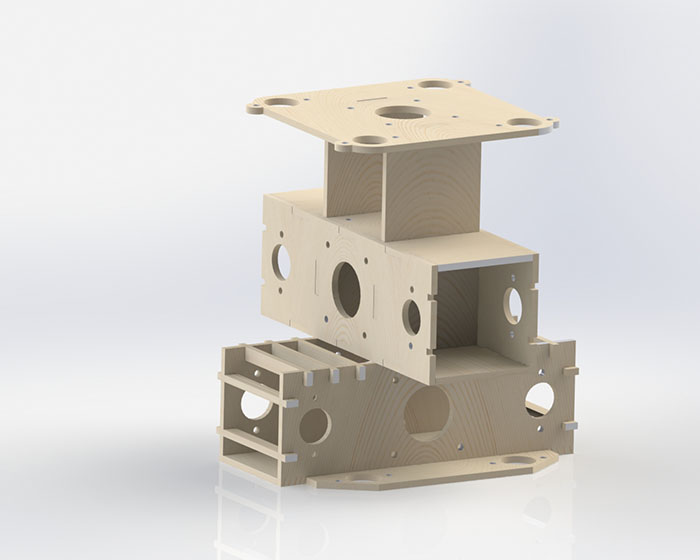
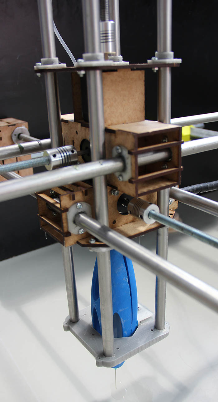
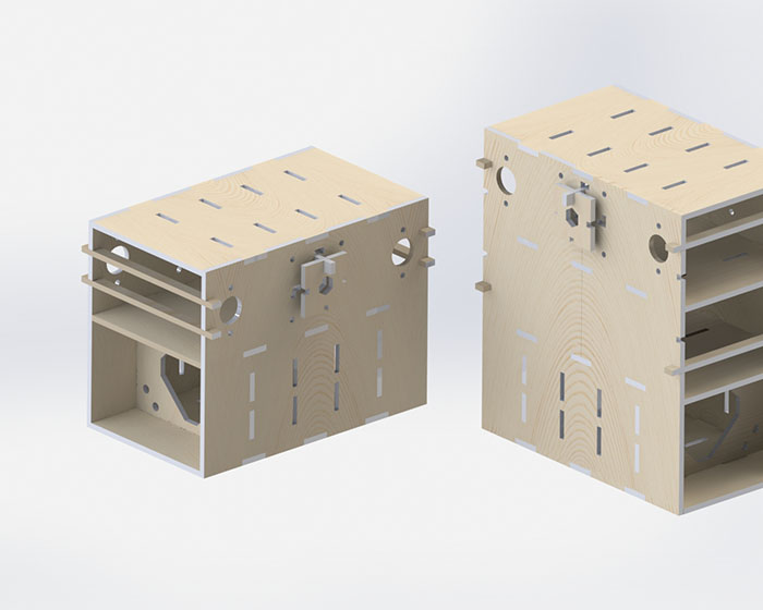
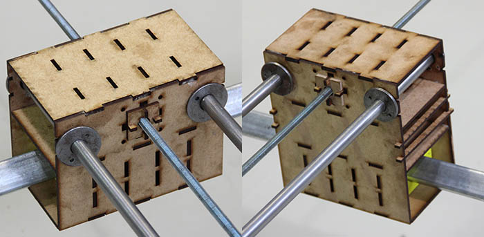
To the new design of the pieces, I combined 2D and 3D design to make in 3D print and laser cut.
This piece contains the motors to different axis and the extruder in the Z-axis. I make this in laser cut.
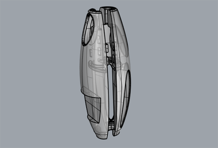
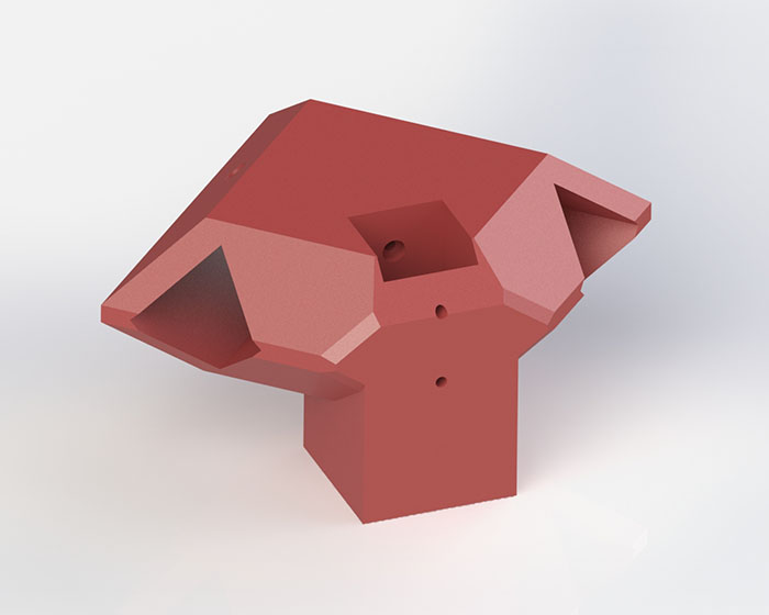
To my extruder I take the design the "Bioma" the machine of previous academy of Ecuador. This piece is make in 3D printing.
Next left a link for access.
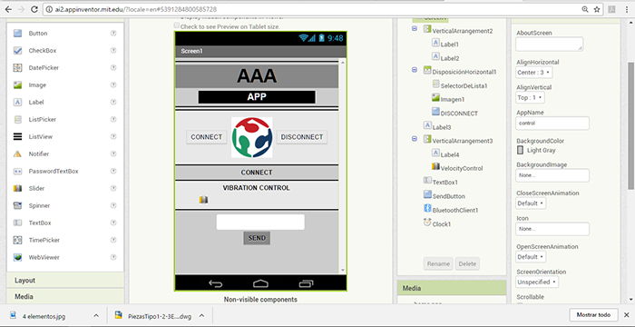
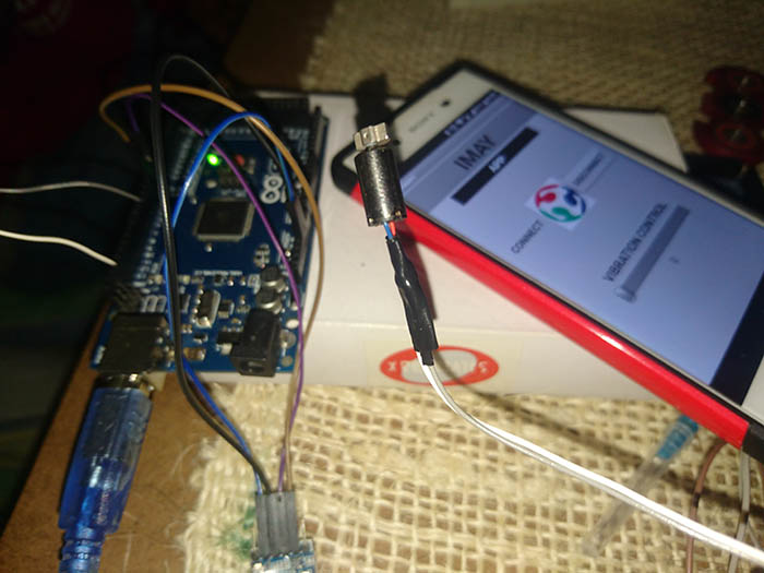
This application can control the vibration motors using a slider from zero to one hundred, this slider change the voltage value
to increase or decrease the intensity of vibration.
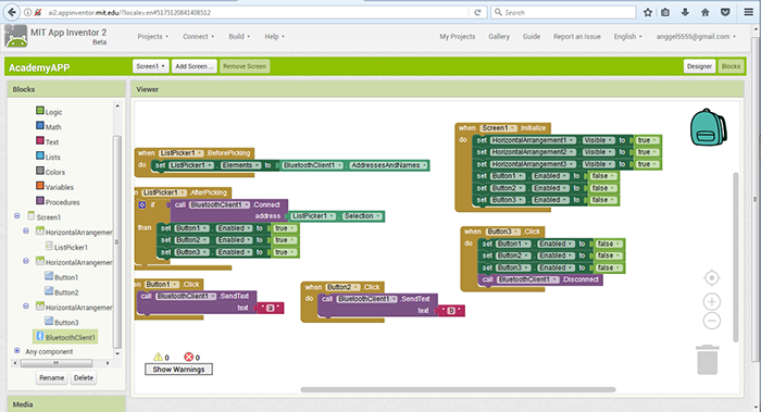
To make this application, I using App Inventor in a process I make the communication of the smartphone with the board designed
by a bluethooth module.
Steppers Motors Control
Output and Input Devices
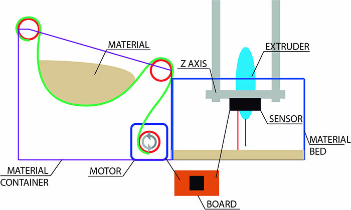
This system perform the function of controlling the fall of material, which is activate when the necessary height is greater to
the determined height which allow the activation of the stepper motor by means of the signals that are sent form the microprocessor
to the drier generating movement in the engine and this in turn drives the mechanism show below.
Materials:
Distance Sensor Sharp ir
Stepper Motor Driver A4988
Bipolar Stepper Motor Nema 17
Board Designed
Embedded programming
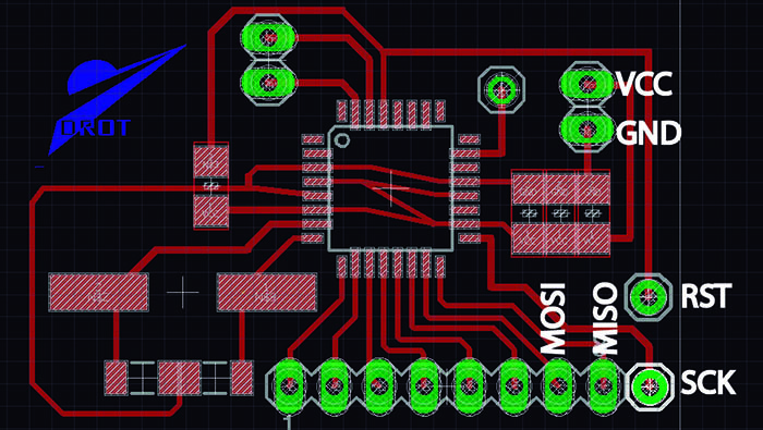
In the next image can see the pins to use for burned bootloader, this pins connect to the Arduino. I use an Arduino Mega to
connect this use the next pins:
MISO: 50
MOSI: 51
SCK: 52
RST: 10
GND: GND
VCC: 5v
Burn Bootloaders
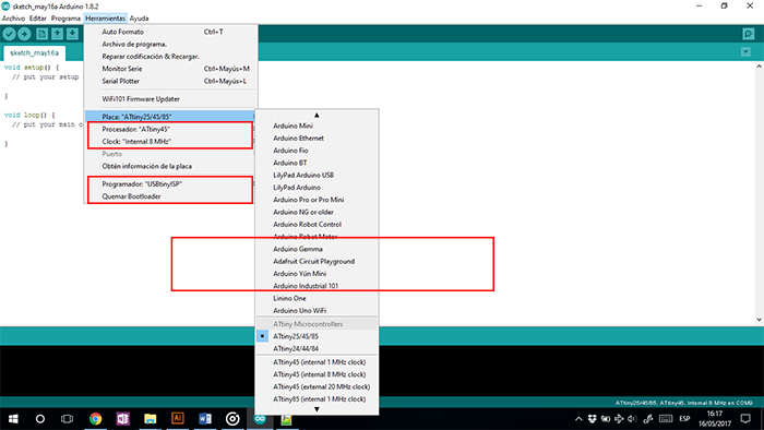
For make this. First select the microprocessor and is recommended work in 8 MHz, to check this
go to “Tools – Clock. In the same window select “USB tiny ISP” by way of programmer.
To end check in burn Bootloaders
Arduino test
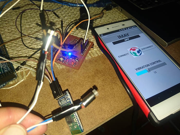
I use an Arduino Mega to make this test, connect the components to a protoboard and the Arduino.
To programing the vibration control, I use PWM pins to can modify the voltage value for make this I use the communication
with TX and RX using a Bluetooth module.
To programing the control of steppers motors, to make this I need the motor, the driver and sharp sensor, in this program
I census the height and this active the stepper motor.
When the two application are finish, I join this in the new file and make the functional test.
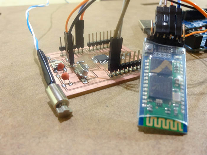
Satsha kit test
In the board, add the programing and the components, to perform an operation test. I take the Satsha kit file in the next page
we have many information.
SATSHA LINK
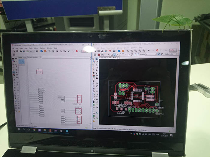
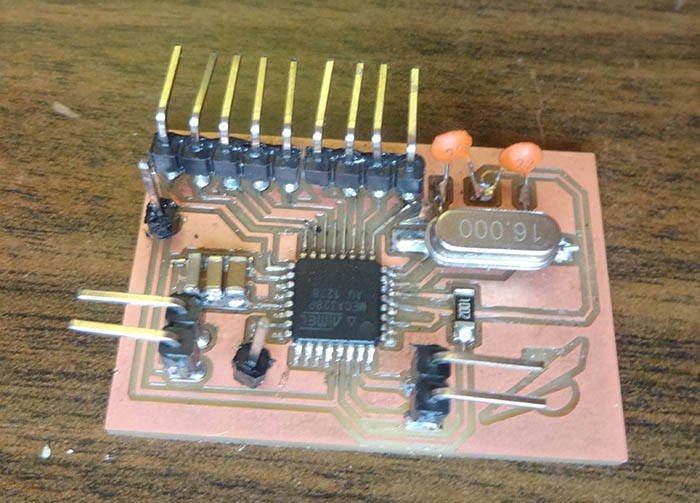
PCB board
To make this board, I modify the design based on my needs. I remove some headers and change the position of different components
and optimizing the components and position of the pins to my project.
What tasks have been completed, and what tasks remain? / What have you worked? What has not?
Only the vibration system remained unfinished in which it lacked a little more work to be able to apply it correctly.
What questions do you need to be resolved?
How to the vibration system compact the material correctly?
What will happen when?
Find the right way to generate material compaction
What have you learned?
I learned design and electronic production, embedded programming and improve skills in design and composite.