#week 10
OUTPUT devices
This weeks assignment
Add an output device to a microcontroller board you've designed and program it to do something
Connecting a stepper motor to the AtTiny board
and programming it
Since we are making an interactive game with two stepper motors on our group project, I chose to use the steppermotor as my output device for this week. The board I chose to program it was my FabISP (that I had trouble getting to work, but fixed it through this debugging) and AtTiny that I made in week 6 and programmed in week 8.
List of materials
• Arduino UNO
• Makeblock microstepdriver
• AtTIny
• FabISP
• 1 steppermotor
• USB cable
• Mini US cable
• 9 cables
• Powesupply
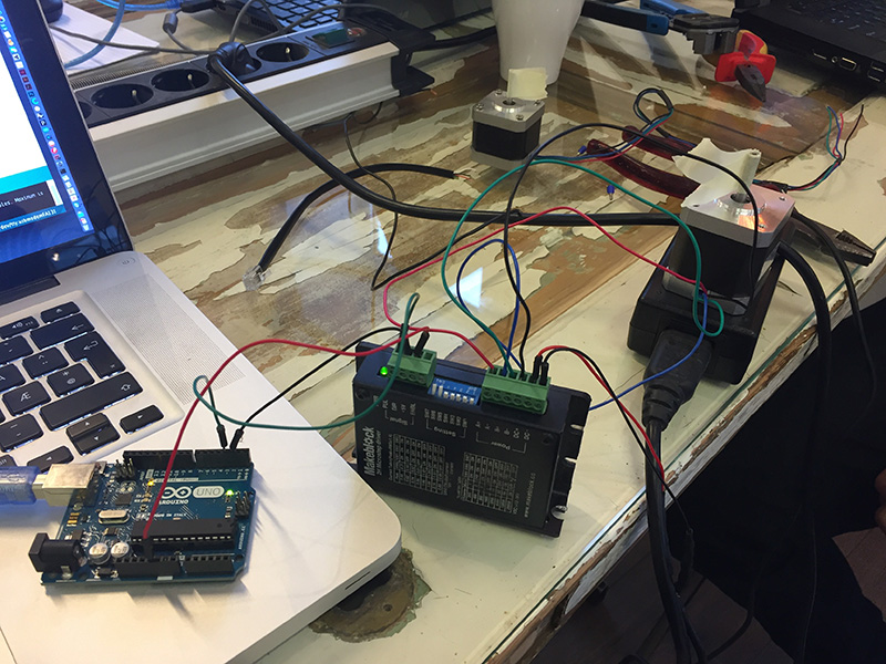
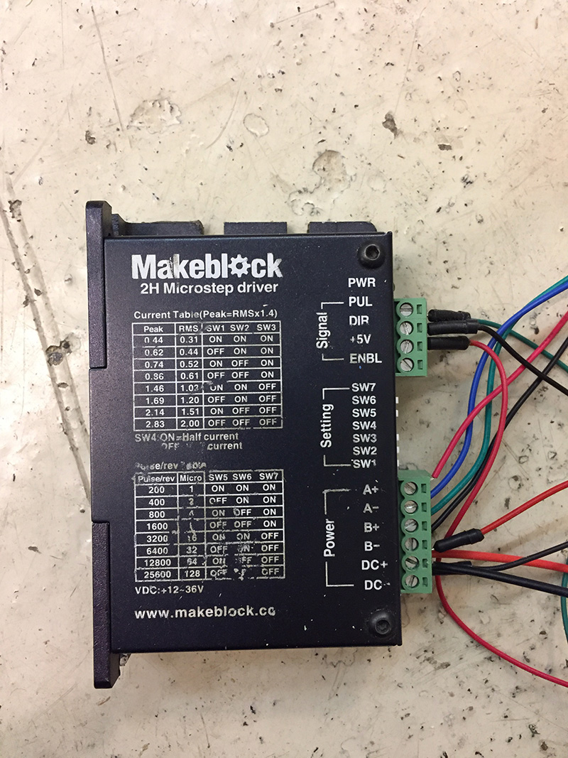
Connecting the Arduino to the MakeBlock Microstepper Driver
From the MicroStepper to the Arduino, the connections was set to:
DIR_PIN_ A to: 2
STEP_PIN_A: 3
5V to 5V on Arduino
The Stepper motor was set to:
Red: A+
Blue: A-
Green: B+
Black: B-
Power:
5Volt: DC+
Ground: DC-
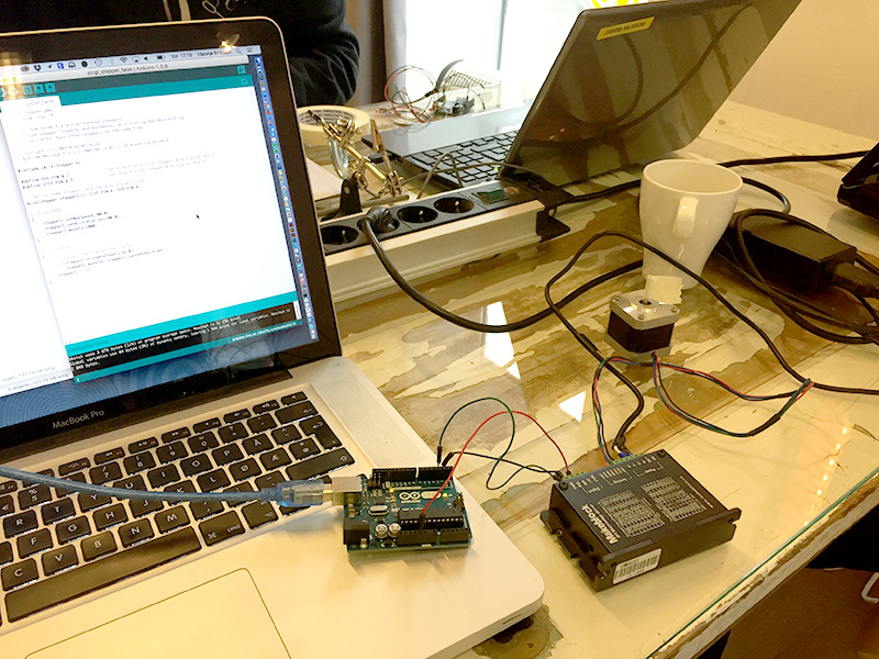
Programming with Arduino
Before programming the AtTiny, I made a test by programming the Arduino and running the code for the steppermotor. The code I run was "single_stepper_fade.io" from Fellesverkstedet repository on Github.
For this code, you also need to install the library from the same repo - called "AccelStepper".
Define pins to:
DIR_PIN_ A to: 2
STEP_PIN_A: 3
You can see a video of it working here
THE CODE
// MultiStepper.pde
// -*- mode: C++ -*-
// Shows how to multiple simultaneous steppers
// Runs one stepper forwards and backwards, accelerating and decelerating
// at the limits. Runs other steppers at the same time
// Copyright (C) 2009 Mike McCauley
// $Id: HRFMessage.h,v 1.1 2009/08/15 05:32:58 mikem Exp mikem $
#include <AccelStepper.h>
#define DIR_PIN_A 2 //Set Direction Pin for Stepper A to Digital Pin 2
#define STEP_PIN_A 3 //Set Step Pin for Stepper A to Digital Pin 3
// Define some steppers and the pins the will use
AccelStepper stepper1(1, STEP_PIN_A, DIR_PIN_A);
void setup()
{
stepper1.setMaxSpeed(200.0);
stepper1.setAcceleration(100.0);
stepper1.moveTo(1000);
}
void loop()
{
// Change direction at the limits
if (stepper1.distanceToGo() == 0)
stepper1.moveTo(-stepper1.currentPosition());
stepper1.run();
}
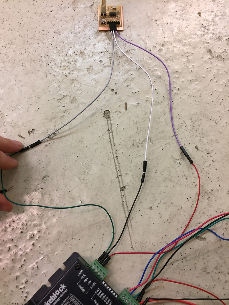
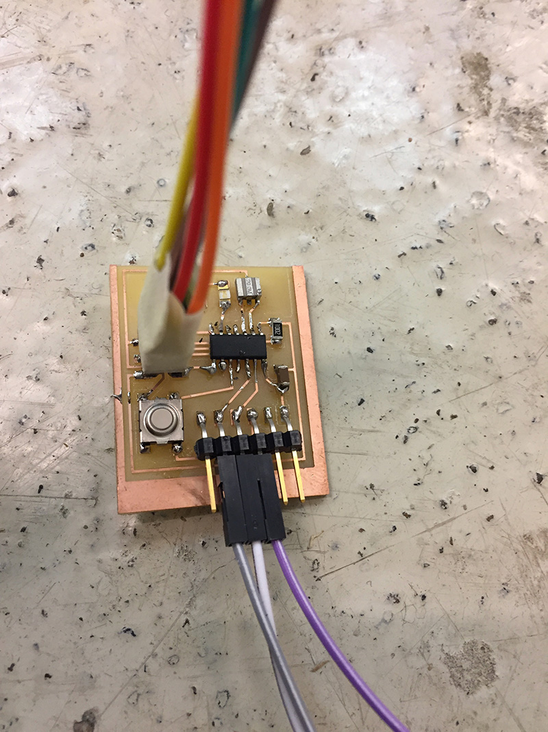
Connecting the AtTiny to the Microstepper
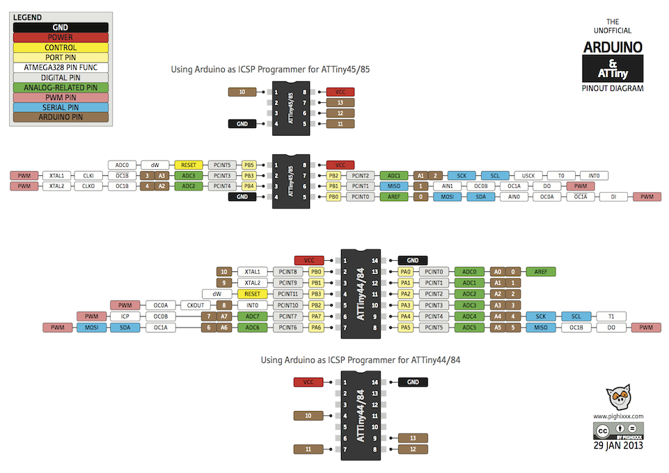
After the test run - I swapped the Arduino with the AtTiny. For working out what pins to use - I used the schedule "Arduino & ATTiny Pinout Diagram" that is shown to the right. The schematic I used was the number 3 from the top.
You can see a video of it working here
The pins ended up beeing:
2 = 11
3 = 10
5v = 1
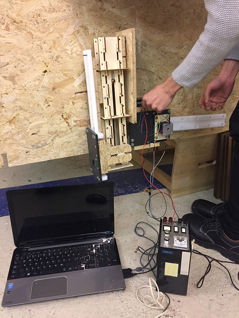
Mounting the steppermotor
Both Jakob and I used our AtTiny's for the machinedesign project. We mounted them on each of the two axis on the pingpong game for controlling the two steppermotors that would loop the code we had tried for the testrun.
You can see a video of the mounted stepper on the axis here
To read more about the Machine design project - go here