#week 6
Electronic design
This weeks assignment
Redraw the echo hello-world board, add (at least) a button and LED (with current-limiting resistor), check the design rules, make it.
Eagle
For this week I chose to follow the steps that was listed on the page:
http://docs.academany.org/FabAcademy-Tutorials/_book/en/week6_electronic_design/eagle_english.html
This page gives a clear and step by step how to go about using Eagle for the editing of the hell-world board.
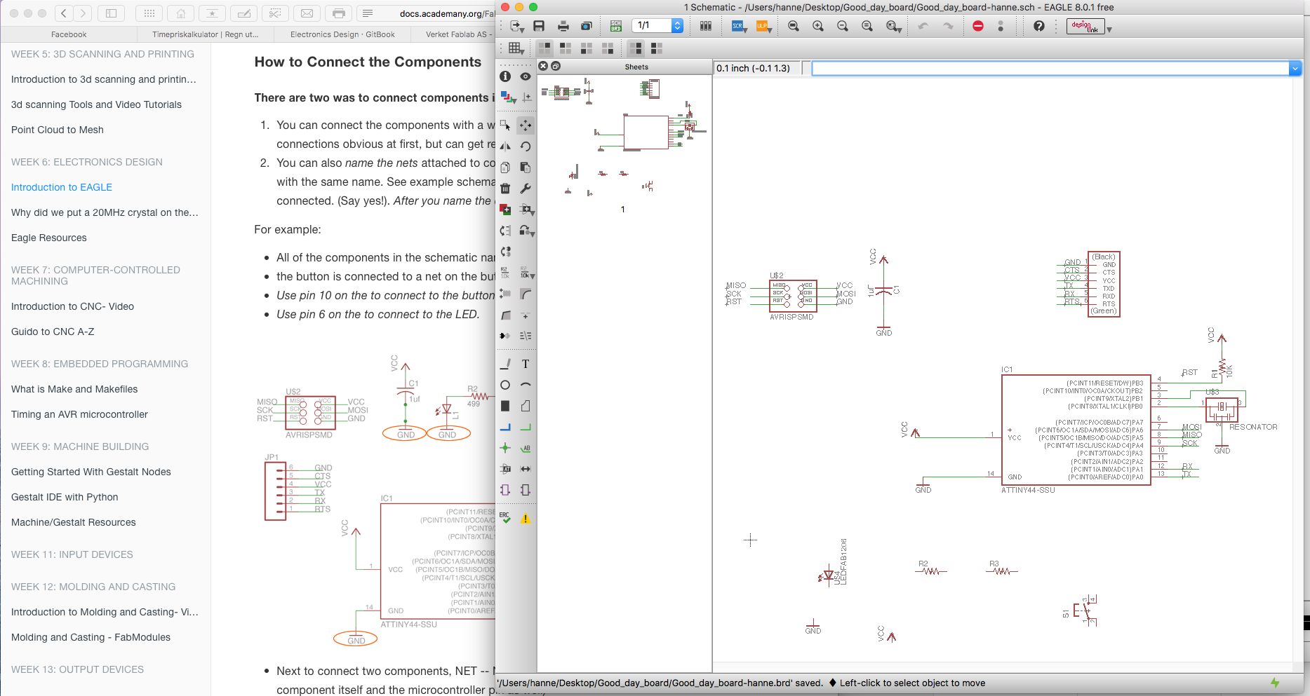
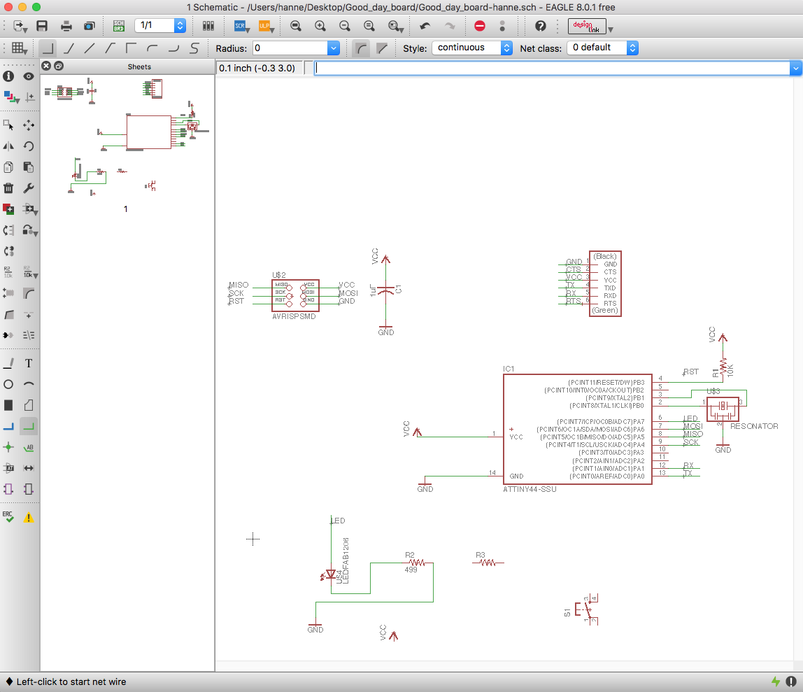
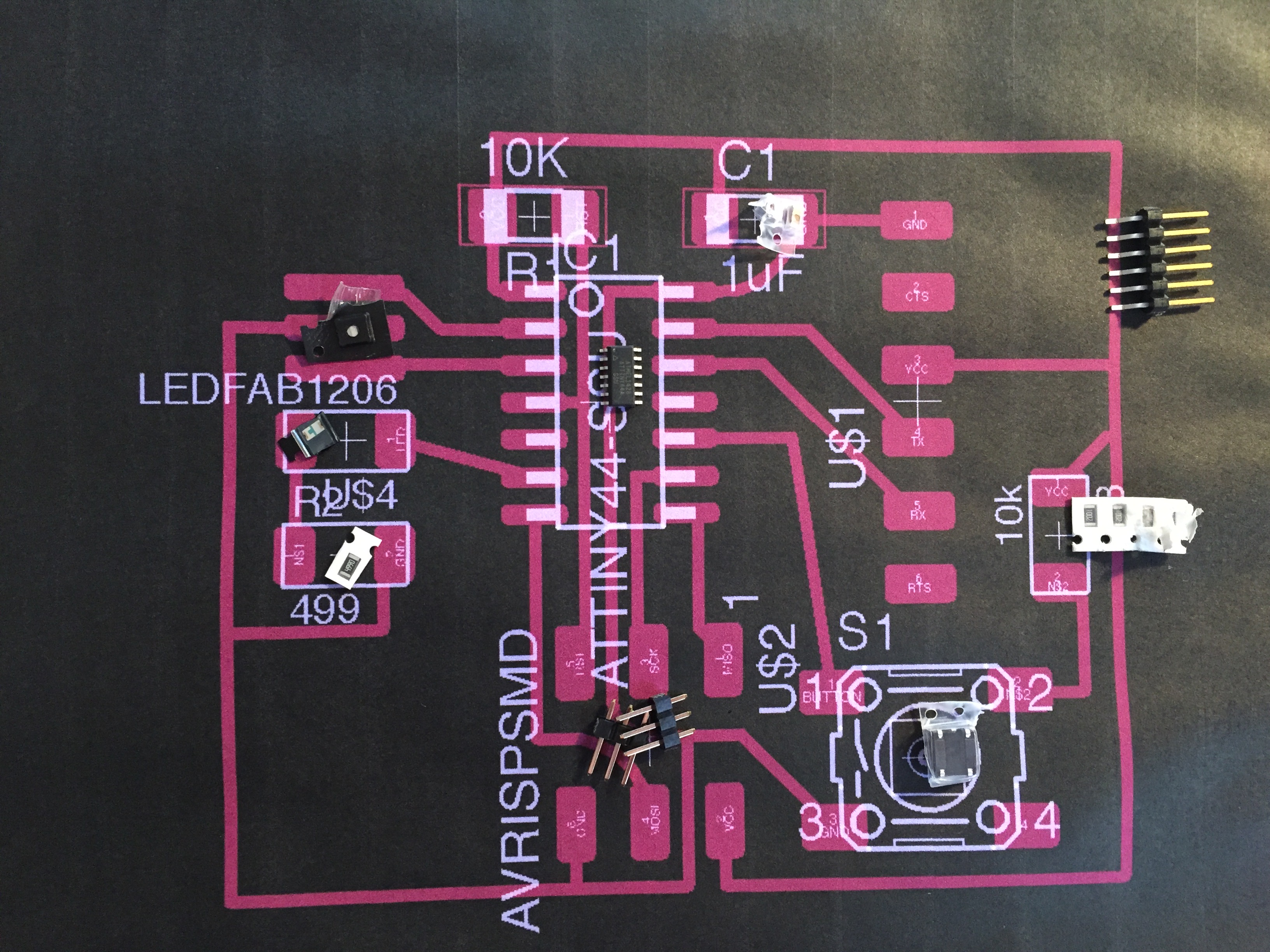
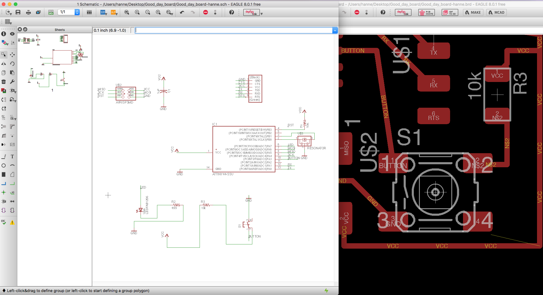
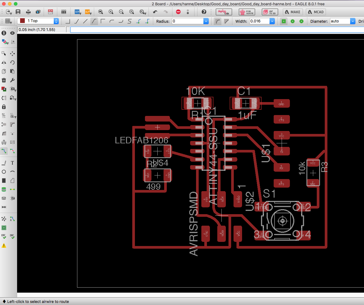
The "thing" about Eagle is that you need both the window for the schematics and the board open. In the schematics you load the components that you need on the board, and connect them together around the page. In the board window you go over and make sure the layout is how you want it, and place the components correct where you want it. Here you can delete traces and connect them as you like. The most interesting I found out in this project was how you have to solve the layout/routing - over/under on the board. I had a preconception that this was very much predetermined and that the program would solve this itself - so that there would not be an option on placing it differently. (there might be a way that this is possible but I did not find that at this point.)
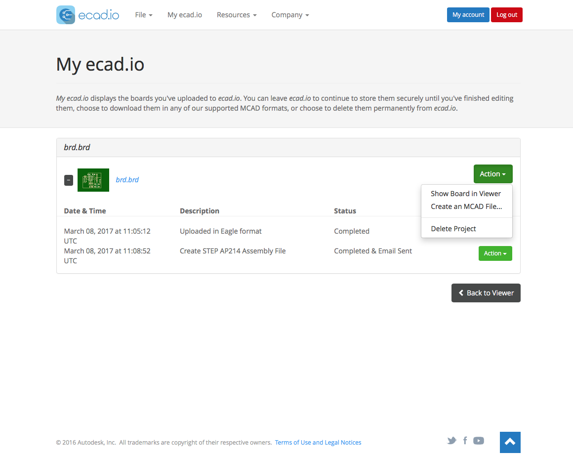
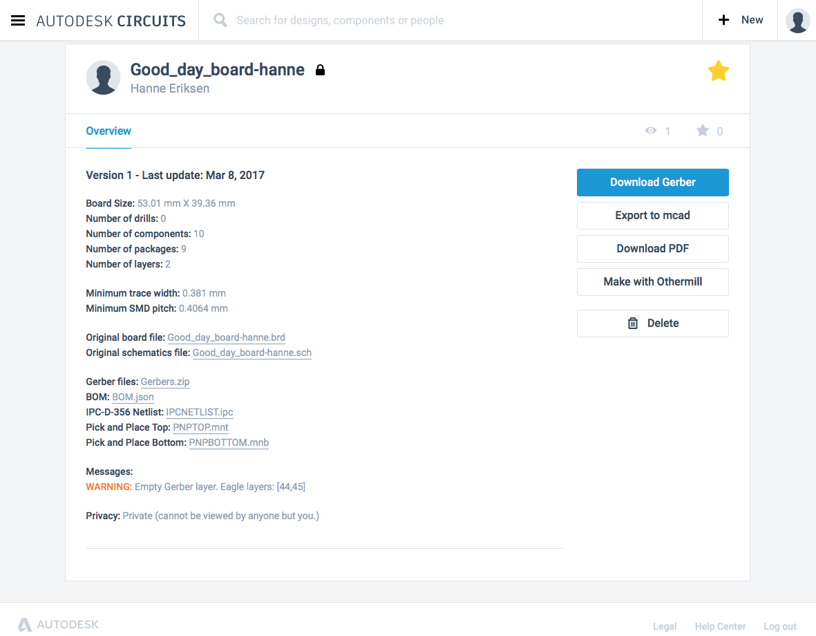
After I finished the design in Eagle, I exported the files directly from Eagle to Fusion360. There is a button in Eagle in the top menu bar - that is called "Make". This sends you to their homepage Myicad.io - where you choose the action "Create Mcad file". From there you download the mcad file and open it in Fusion360.
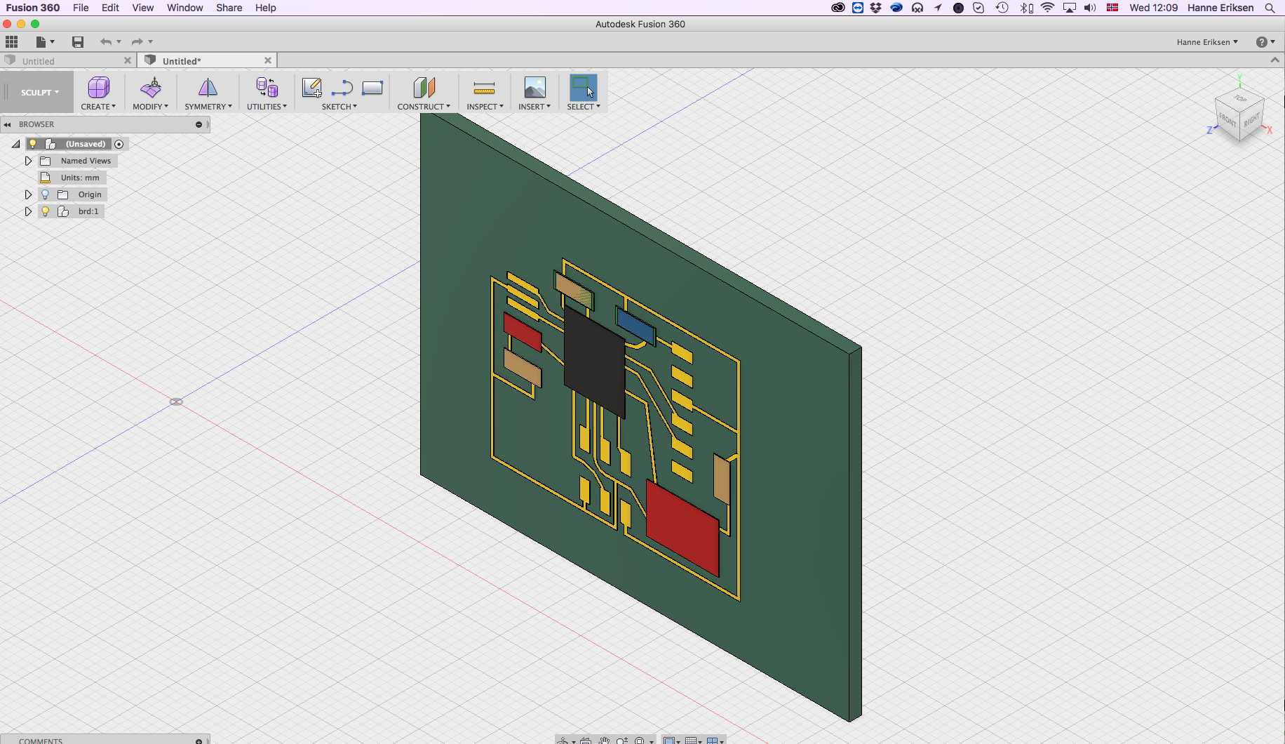
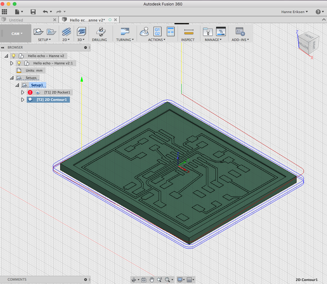
In Fusion, I added the contour around the circuit and the cut path for cutting out the board.
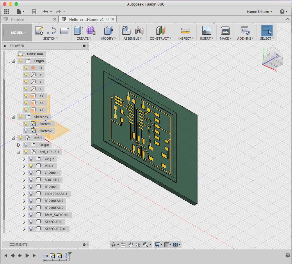
I then created the CAM setting for the milling job, with these settings:
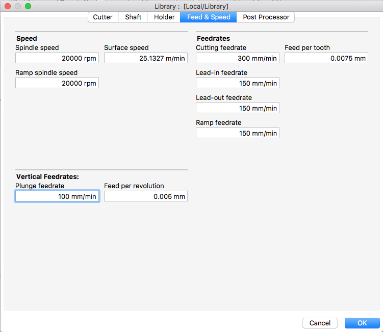
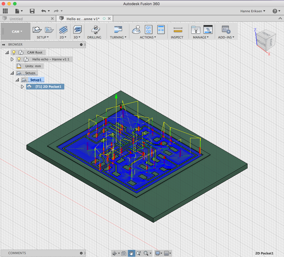
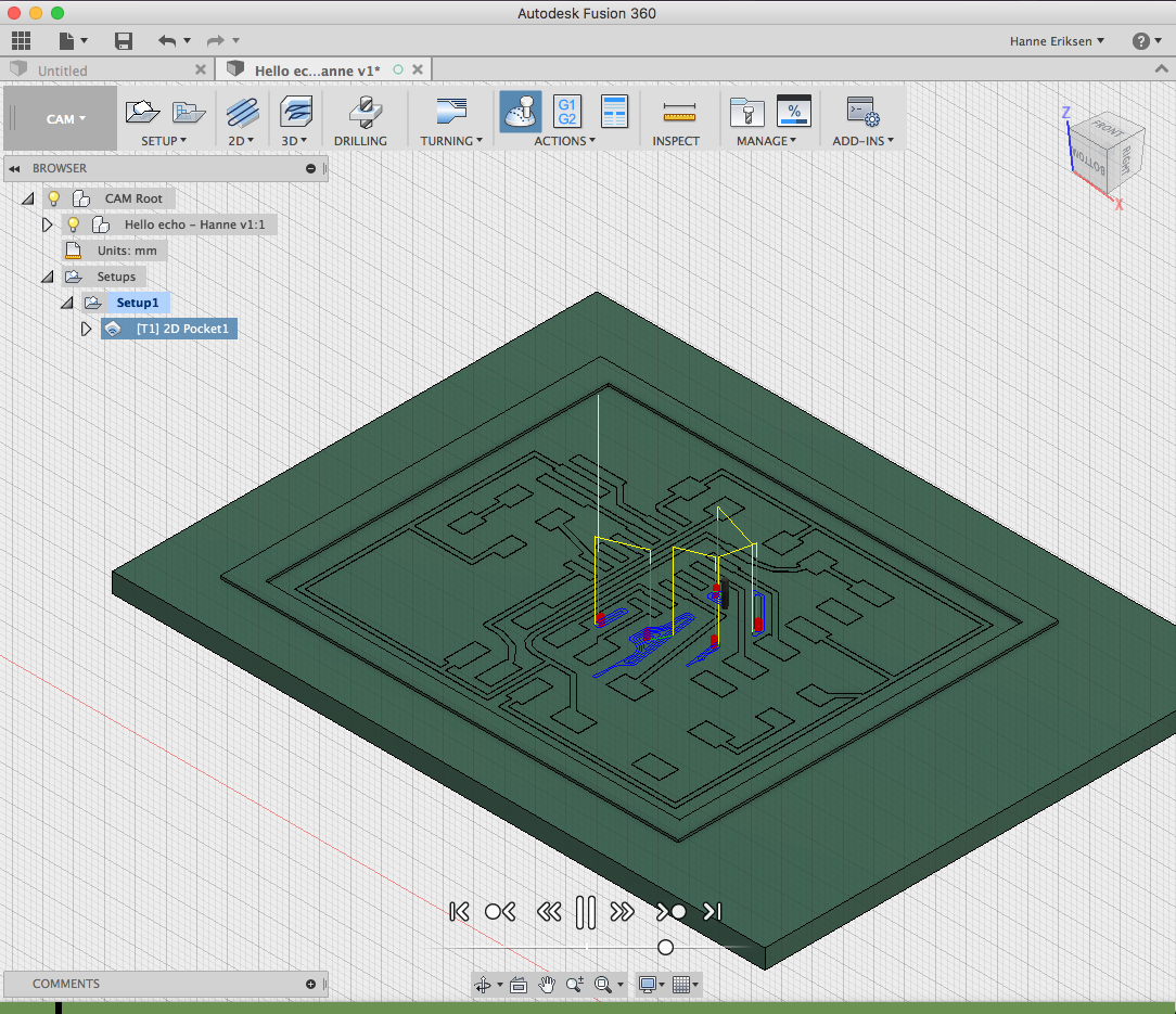
And before posting the job to gerenate the code, I did a simulation to check that everything was showing correctly. This simulation showed that the spindle was doing an unessesary long helix operation while plunging. I then went back and reduced the height of the helix function.
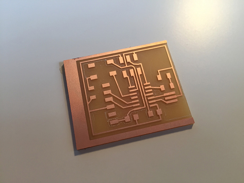
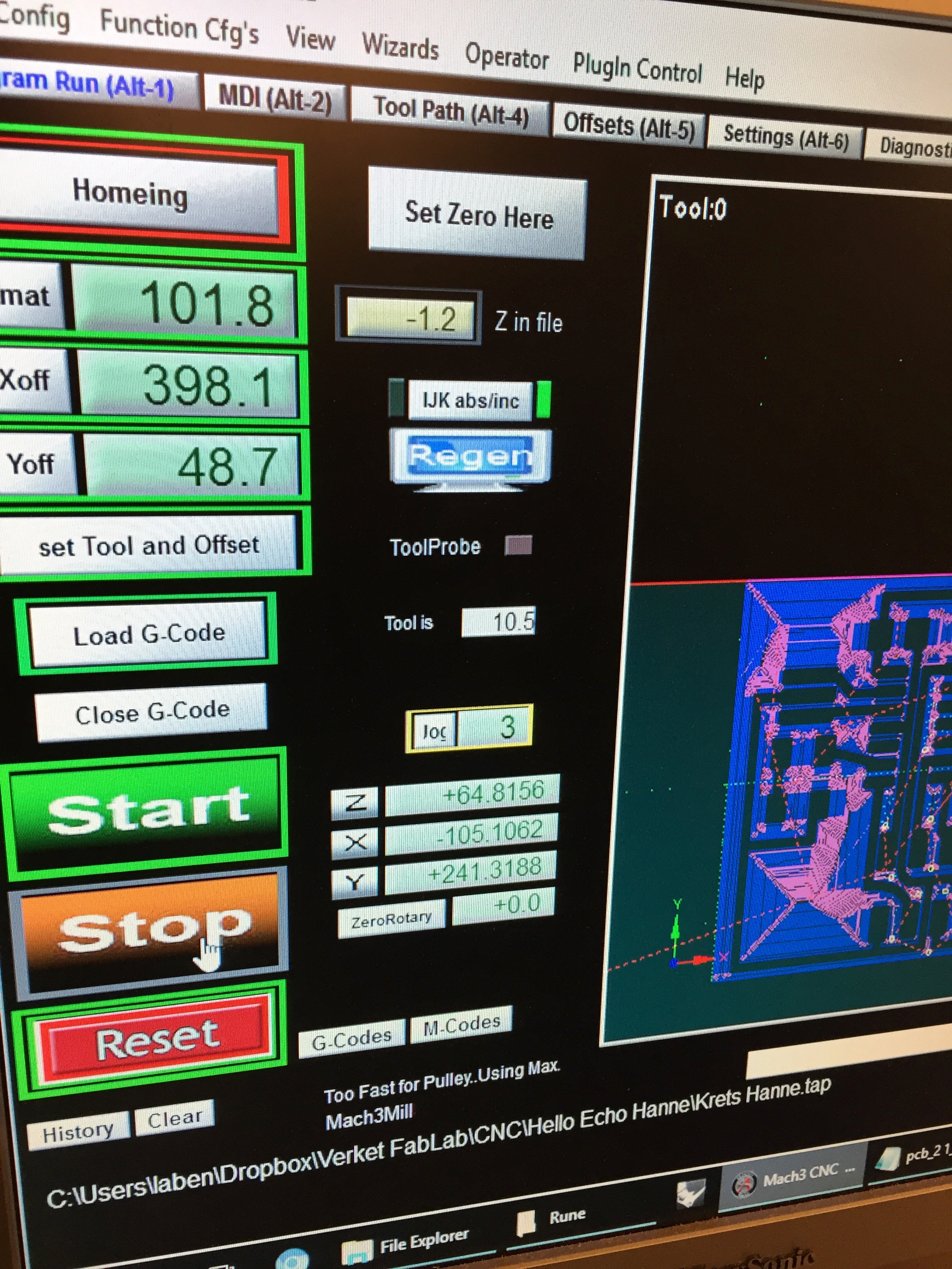
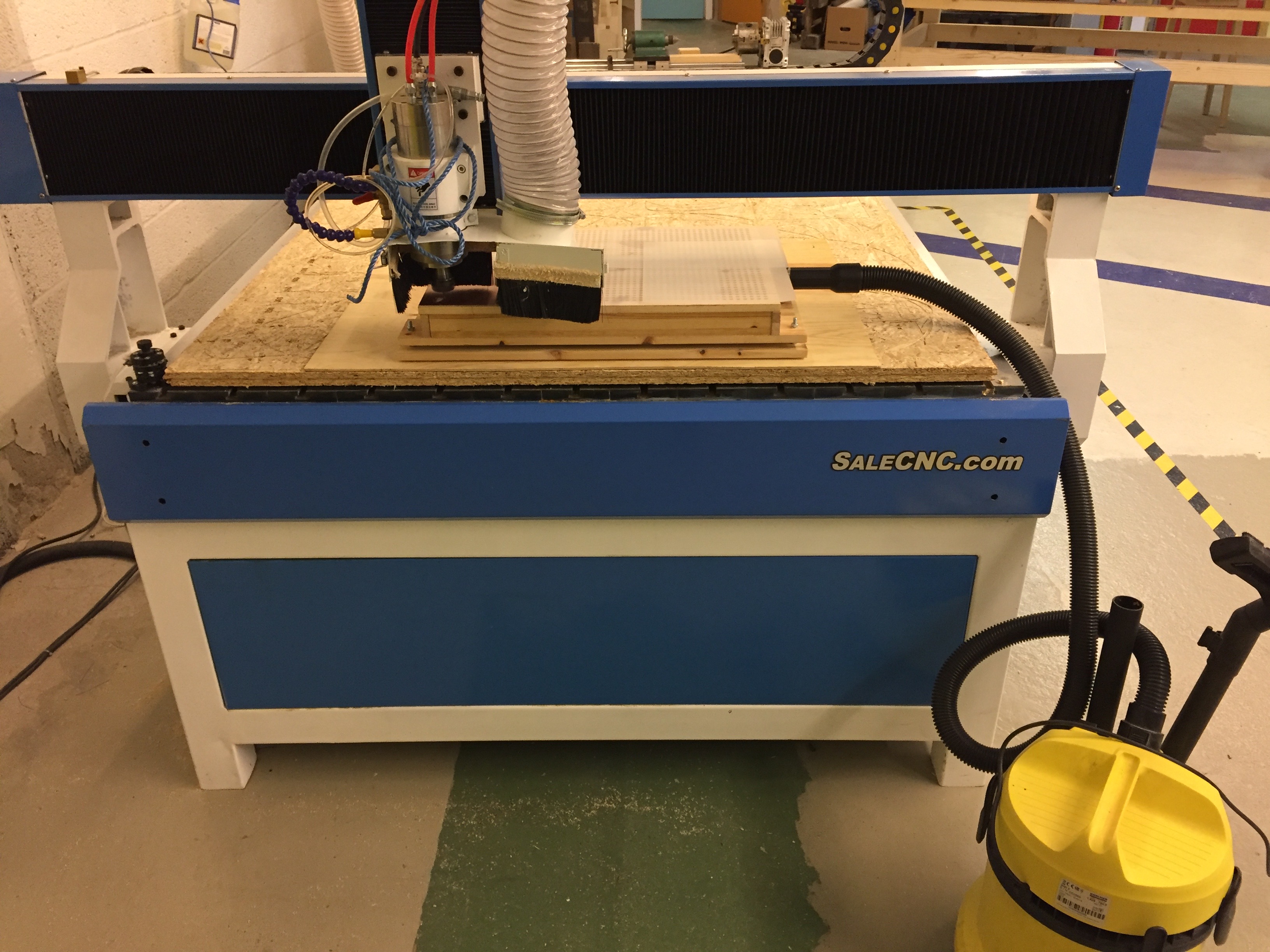
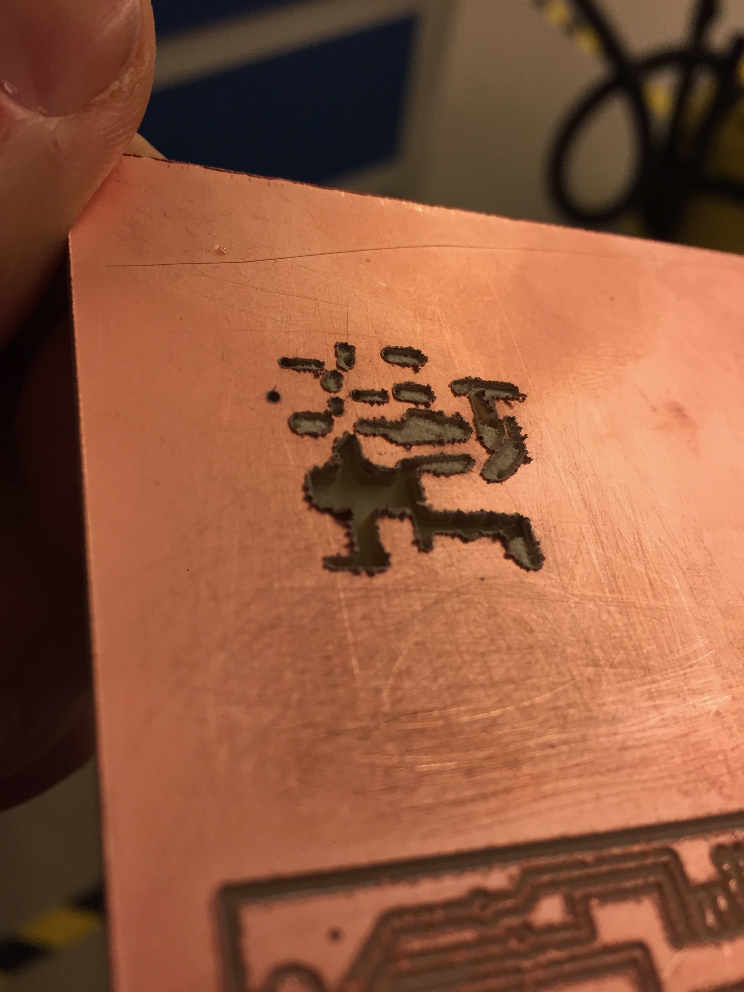
When I was ready with the files, I imported it to MACH3 for the PCB milling. The first time around I managed to forget to check the z in the file (showing -1.2 in the picture below). This resultet in the milling bit going way to deep into the PCB (impressingly enough, this did not break the bit!). So I made a second job where I adjusted the height for the right job settings.
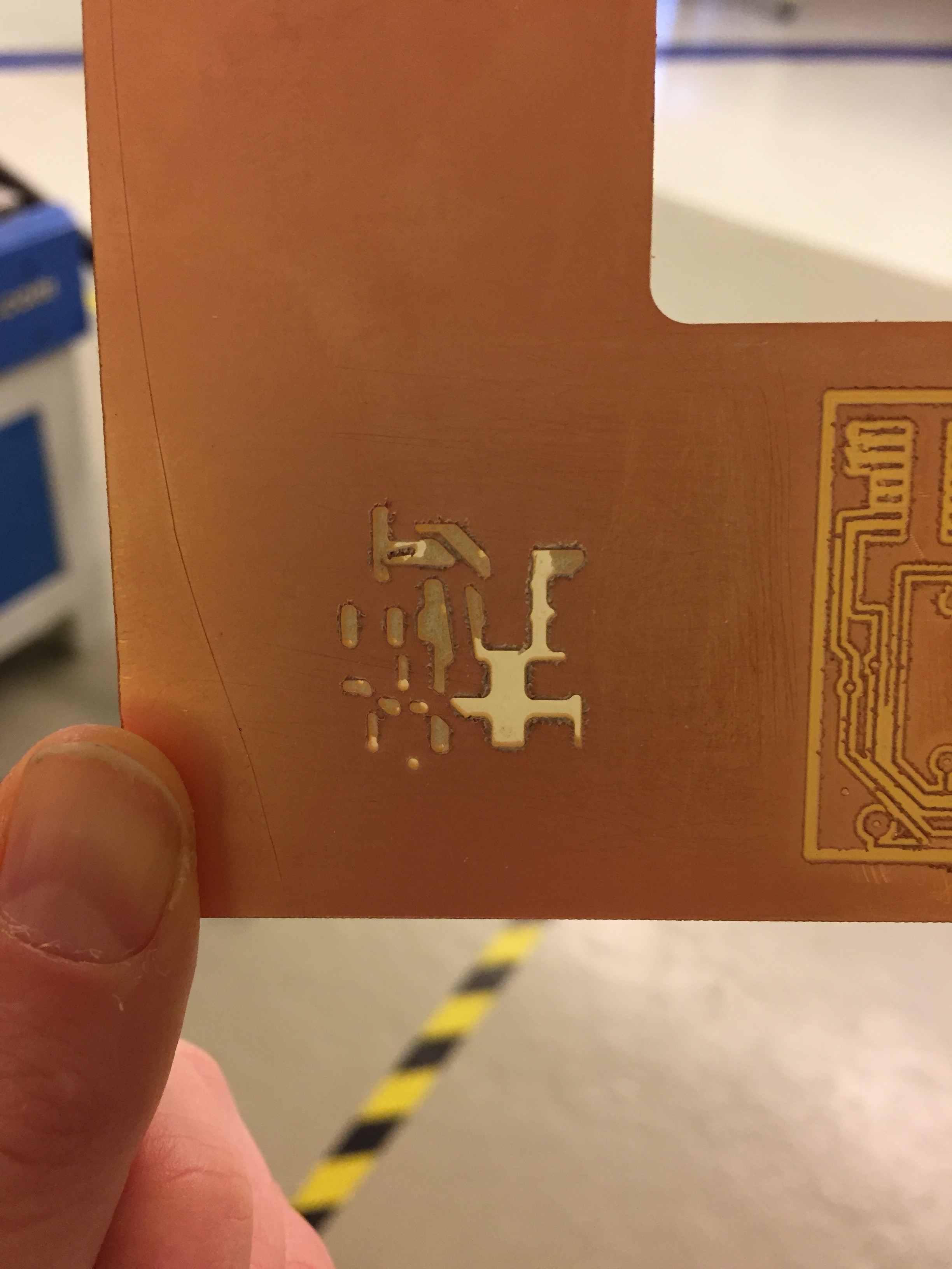
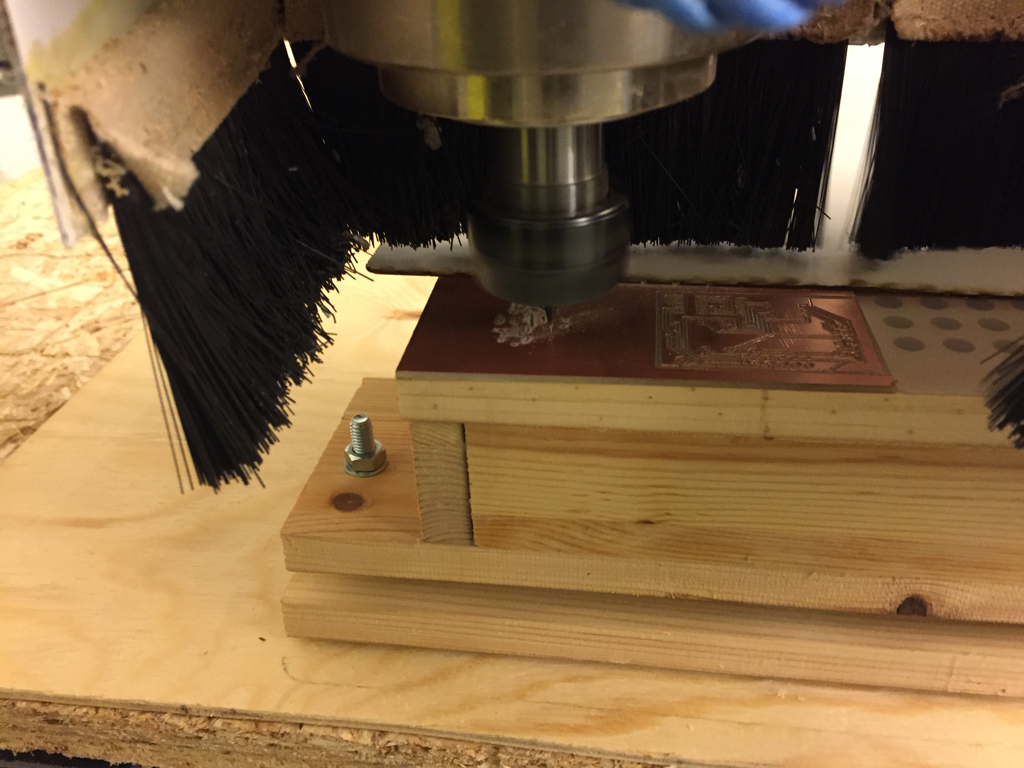
2nd round
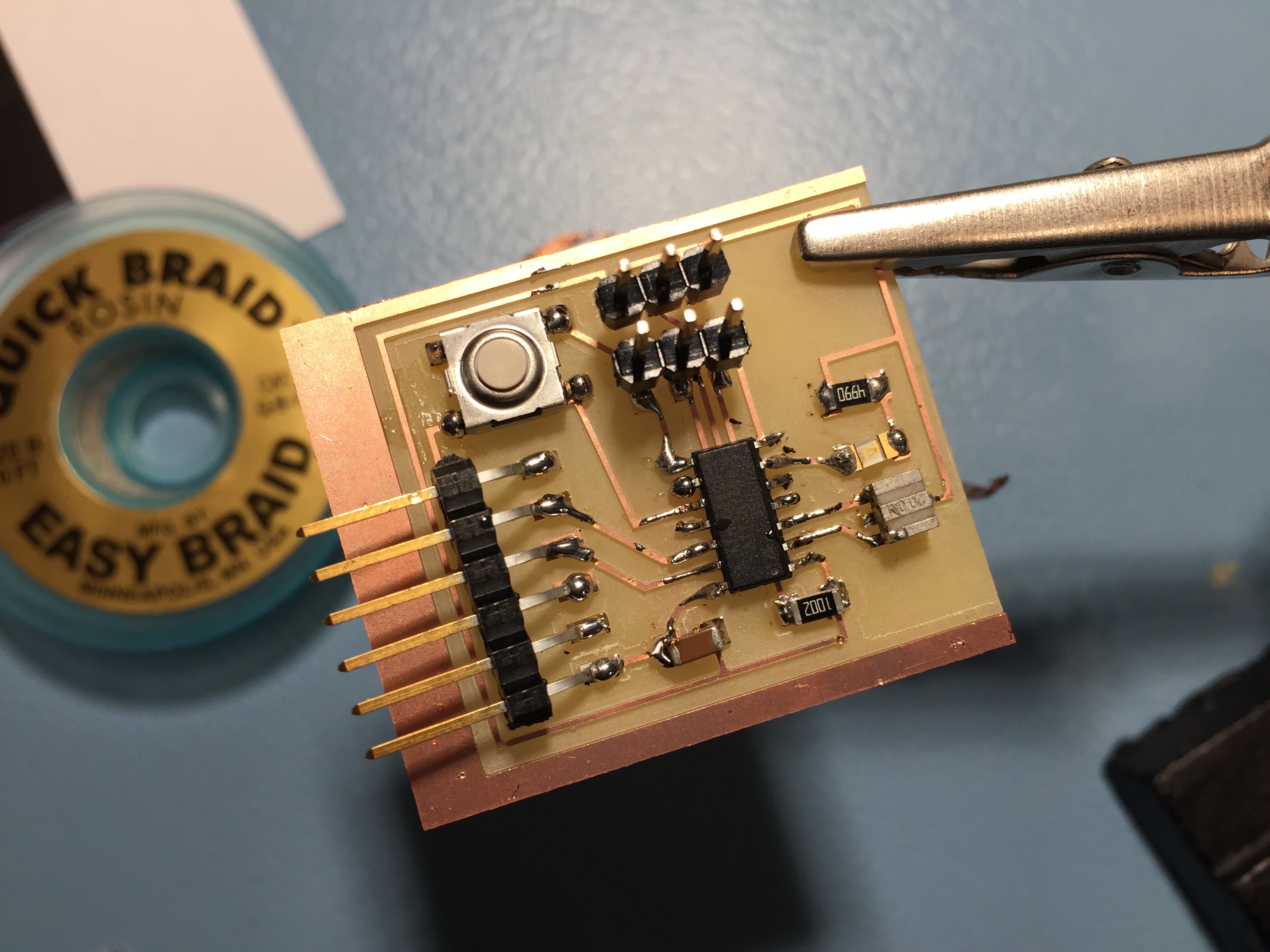
After milling the PCB, it was ready to get soldered! This part went a lot quicker than the first board we soldered, and it was quite cool to solder a circuit that I had "designed" myself and actually understood how the layout worked.