
Door bumper
3D scans
My designed test prints
Several years ago I built and experimented exensively with an Ulitmaker 1 which is a filament deposit 3D-printer. I then focused on high speed printing and investigated what limits how fast you could go.

.jpg)
I used the data that I gathered to write a crude "Flow thermostat" Cura plugin which aims to connect temperature control to the individual layer cooling time. I hope to revitalice the plugin and for this purpose I put up a separate Flow thermostat project page so I can keep track of it.

Verket Fab Lab is registred on 3d-hubs, a distributed 3d-printing service. This means that people can online-order prints to be made in the lab, for a fee. These machines are available in the lab:
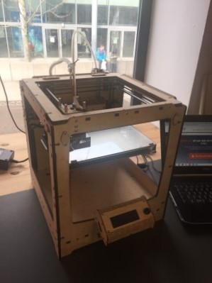
I built one of these in 2011. I have since donated it to the Oslo hacker/makerspace Bitraf, where it has been and is in continious use. It is serviced and upgraded by the members using it. I was satisfied with its high speed motion capacities but it's weak points were the original extruder grip and hotend max temperature.
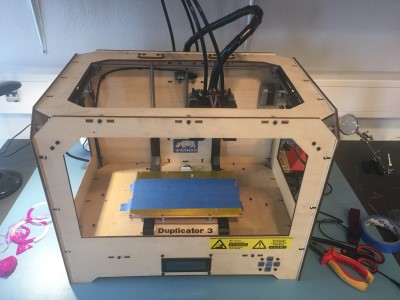
Could not find an offical site for this version. Made by WANHAO USA
It is eqiupped with two printing heads and has the extruder feed mechanism mounted right next to the hot end, this makes it more suited for printing with very flexible filaments compared to the other machines who feed the filaments through long bowden tubes between the extruder and the hot end.

Official site for Ultimaker2+
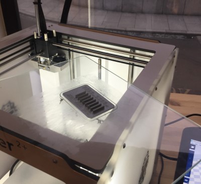
This is the printer I have been using for this weeks experiments. I am pleased to see that the main weak points in the Ultimaker 1 one has been adressed. The interface also feels quite a bit more professional.
.JPG)
.jpg)
These filaments types are available in the lab:
Acrylonitrile butadiene styrene (ABS) is a common thermoplastic polymer. Its glass transition temperature is approximately 105 °C (221 °F).[2] ABS is amorphous and therefore has no true melting point. For the majority of applications, ABS can be used between −20 and 80 °C (−4 and 176 °F) as its mechanical properties vary with temperature. The properties are created by rubber toughening, where fine particles of elastomer are distributed throughout the rigid matrix. Further reading.
Poly(lactic acid) or polylactic acid or polylactide (PLA) is a biodegradable and bioactive thermoplastic aliphatic polyester derived from renewable resources, such as corn starch (in the United States and Canada), tapioca roots, chips or starch (mostly in Asia), or sugarcane (in the rest of the world). In 2010, PLA had the second highest consumption volume of any bioplastic of the world. Further reading.
Semiflex is a thermoplastic polyurethane (TPU) that is considerably more flexible than the more traditional PLA and ABS. The material TPU has many applications including automotive instrument panels, caster wheels, power tools, sporting goods, medical devices, drive belts, footwear, inflatable rafts, and a variety of extruded film, sheet and profile applications. TPU is also a popular material found in outer cases of mobile electronic devices, such as mobile phones. It is also used to make keyboard protectors for laptops. TPU is well known for its applications in performance films, wire and cable jacketing, hose and tube, in adhesive and textile coating applications and as an impact modifier of other polymers. Further reading.
This was assigned as a group exercise. Me and Hanne (the other student locally here in Verket Fab Lab) discussed it and decided that we will use predesigned test prints from online sources. We will then try the same prints on the different printers in the lab to see if the results differ. I did choose the Ultimaker 2+ and Hanne worked with the Ultimaker+. We also ended up doing additional test related to our individual projects.
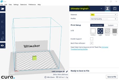
I found the way the new system for material settings to be confusing for a beginner. The official printing software Cura 2.4 asks you to create and select material profiles which it then ignores without telling you. The settings on the machine are used instead and if you want to update them there is a separate process for that.
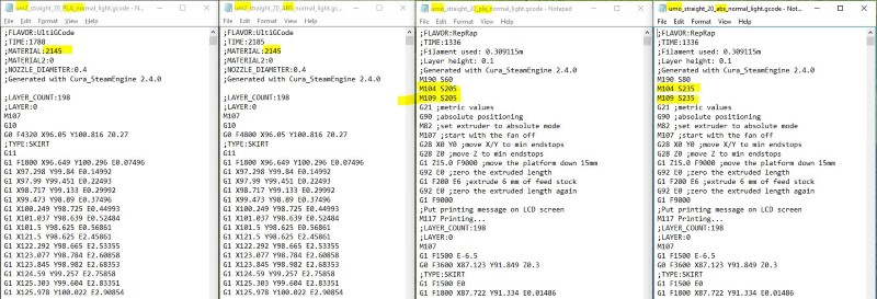
I also made my own experiment, changing the material settings in Cura 2.4 for the official Ultimaker+ and Ulitmaker2+ machine profiles and compared the Gcode output. The code generated with Cura 2.4 for the Ultimaker 2+ using ABS or PLA does not contain any temperature settings, it does when using Ultimaker+ as indicated by the M104 and M109 lines. (Official Gcode commands list)

Apparently it is not only me who found this confusing. Even the official Cura tutorial video misinforms the users by showing them to choose material in Cura for and Ultimaker 2+, this will do nothing.
I posted to the official Cura/Ultimaker forum with a suggestion to change the Cura menu or better inform the users to avoid this confusion.
I first tried printing ABS on blue tape with a heated bed. The corners started warping upwards due to that the ABS contracts while cooling, this caused the print to detach and get ruined.


I removed the tape and leveled the platform then I added glue to improve adhesion and tried again. Same problem twice more. So I switched filamemt to PLA. Instant success.
I really prefer PLA over ABS since the warping that caused build plate disbonding is such a headache with ABS.
Wall / Gap Test Print v2 (Customizable) from Thingiverse. (Backup)

I measured the gap sizes by testing which washers I could fit through them.
Printed gaps are up to 0,2 mm smaller than the theoretical dimension.
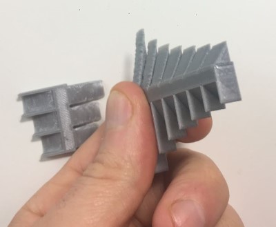
I cleanded of loose stringing and broke off the walls to be able to easily measure both their "waist" and maximum thickness as shown in the pictures.


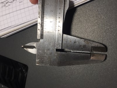
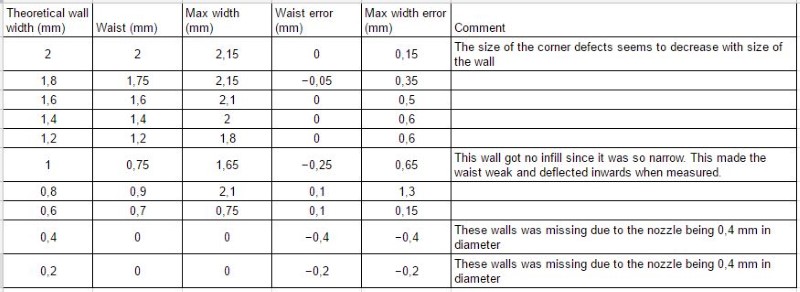
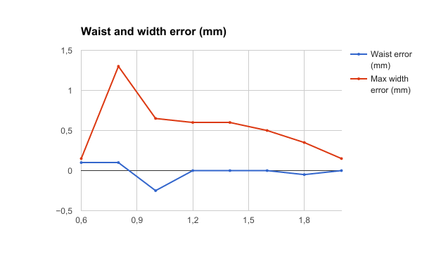
I see that the waist dimensions are way better than the total width, especially for small details where the corners seem to suffer.
Printing errors are more prominent at corners and can be up to 1.3 mm for small details. Waist dimension errors for properly infilled structures can be up to 0.1 mm.
I wanted to see the effects on larger objects so I designed and printed three test boxes with different corners. They are 20x20x10 mm each.
Step model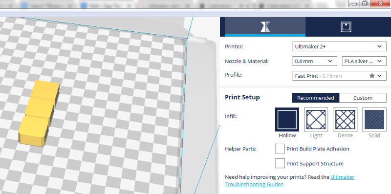

These are the resulting measurements. I measured the maximum width along the whole side of each box.
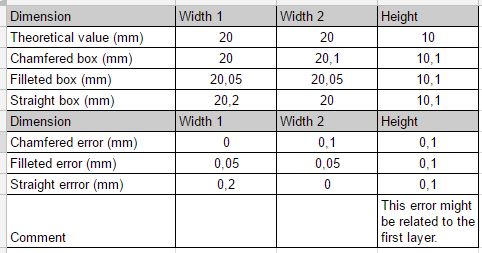

I also measured the waists witout the corners and no errors were above 0,1 mm.
The boxes with altered corners show no additional error on top of the expected 0,1 mm waist error from our previous test.
This implies that rounding or chamfering corners can be a good way of reducing errors for tight fits. However there is a significant possibillity that my errors are created when the printer transitons from one object to the next meaning that the same error could appear in other places as well.
Exterior width dimension errors of up to +0,1 mm is to be expected with the Ultimaker 2+.
Larger errors might appear in sharp corners or where the printer transitions from object to object.
Gaps might be 0,2 mm narrower than intended.
We found this nice bridging test and calibration on the Ulimaker site. Find Hannes tests here.
Using the fast print settings in Cura for Ulitmaker and silver PLA filament. The filament temperature is set on the machine


The results from this "plug and play" test was suprisingly good! I am sure the results could be imroved with further by following the guide, (perhaps by lowering the speed and or temperature,) but it is already very close to what the ultimaker guide deem "Nice bridges".

Desings with long bridges will suffer a sag proportional to their length. Do not desing tight fits around a printed bridge.
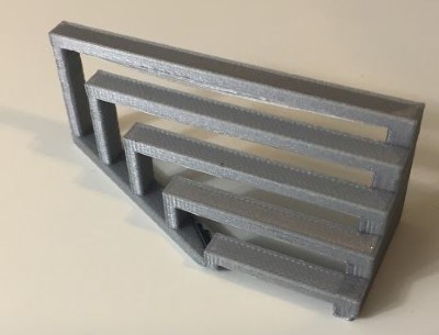
Overhang Test Print (Customizable) from Thingiverse.
.jpg)
.jpg)
.jpg)
Surprisingly good results for my "plug and play" test!
There are some errors in the early layers. That might stem from contamination from black filament residue on the nozzle since my failed test with ABS or overheating due to the heat coming from the printerbed for the first 2 mm.
Clean the nozzle to avoid contamination.
Free overhangs look flawless down to 25-30 degrees.
The Ultimaker 2+ can print functional free overhangs down to at least 12 degrees using these settings and materials.
I wanted to design and print flexible door handle bumpers for my new apartment. I saw that the lab was equipped with Ø3 mm Semiflex filament so I wanted to use that.
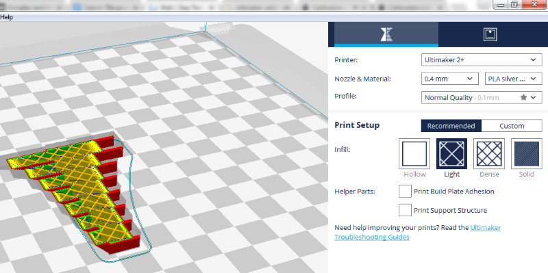
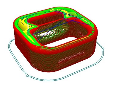
Traditional FDM software like Cura from Ultimaker uses "2D infill." This means that the infill is completely straigth and continious along the veritcal axis (like an extrusion). This will always give the prints an uneven directional flex depending on the print direction. Instead I wanted to experiment with 3D infill, specifically Cubic internal structure such as the Type A Machines generate for their 3D printers using their machine specific version of Cura.
I designed a simple object to test out settings for the infill and wall thickness so that they would provide the right bounce.
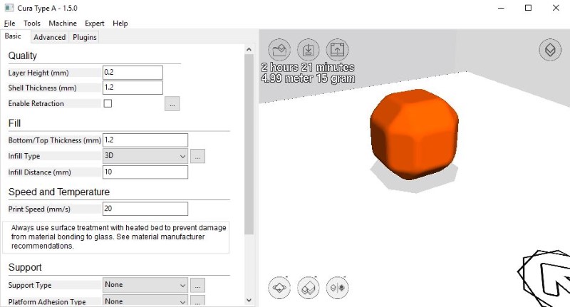
I used settings from the producers site.
Type A Cure profile .ini-file
Most importantly a continious 20 mm/s feed for all printing to keep an even flow with the flexible filament that otherwise will act like a spring in the bowden tube.
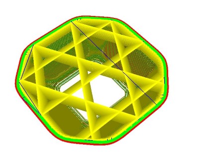
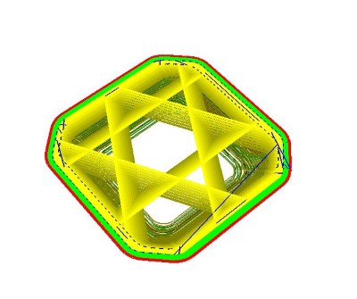
Here you can see a simulation of the 3D infill. Note that the program only renders a few layers at a time, the infill pattern goes all the way through the object and resembles stacked cubes standing on their tips.
I had to add new materials to the Ultimaker 2+ on it's own controller so I followed the official instructions for Material setup on the UM2+ machine. I am amazed that it works so well with generic filament profiles. Previously when I have used the Ultimaker Original filament diameter and precise temperature control was apsolutely crucial. The improved extruder and hot end must be more forgiving!
Type A machines does not come with a postprocessor for Ultimaker 2+. This meant that the gcode generated did not work plug-and-play. Since I could not find a way to easily alter the postprocessor I choose to copy in an replace the "start" gcode from a reference file generated with regular Cura. It is quite possible that the fan off and retraction instructions were unecessary and plain coordinates would have worked, I'll try that next time.

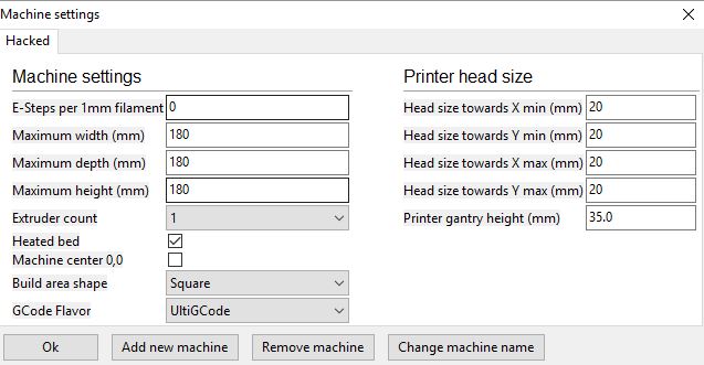
I also altered the machine settings since the type A machines are considerably bigger than the Ulitmaker.
This together made the part print fine in the flexible filament.


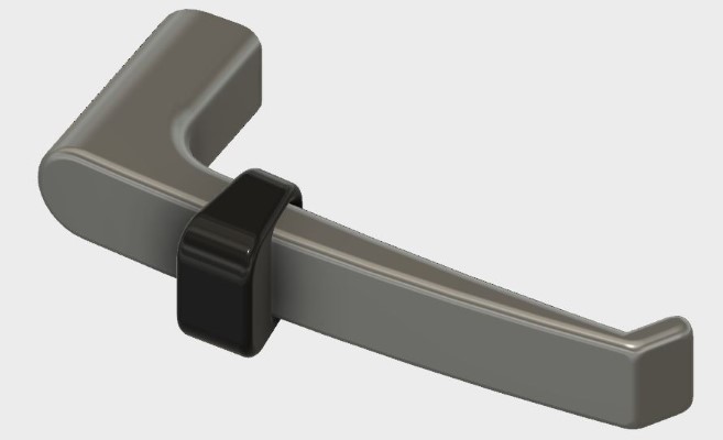
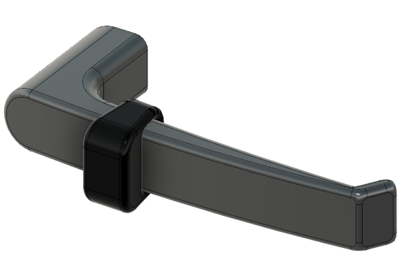
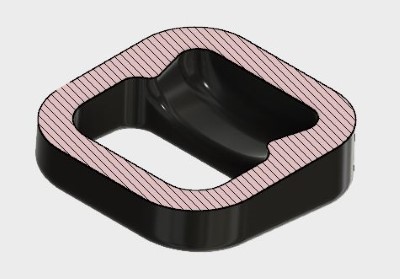
I designed my door bumper and its handle (for reference) in Fusion360. I gave it an internal cavity to give it a more interesting shape and to contol how it would compress when "bumped" against the wall. The inside cavity would be impossible to machine with 3 axis subtractive machining techniques.
I first measured the handle I wanted to design a bumper for and then recreated the handle dimensions in a fusion 360 sketch.

Extruded the sketch to form the handle body.
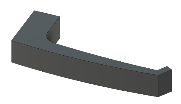
Added approximated fillets to all edges.

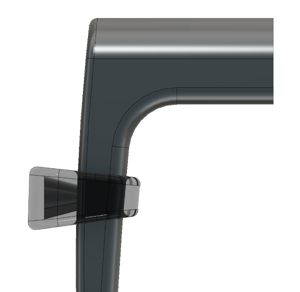
Created an offset plane and a sketch where I wanted the bumper to snag on the taper of the handle
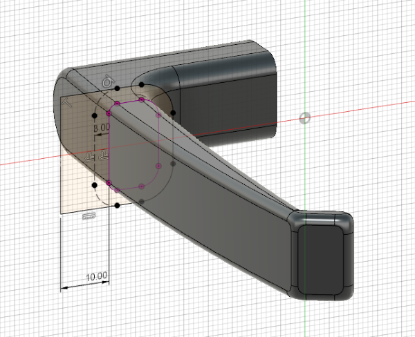
Created a second plane at the intended width of the bumper

Lofted the two sketches together to form the bumper body. This makes the bumper inner and outer shape follow the handle evenly.
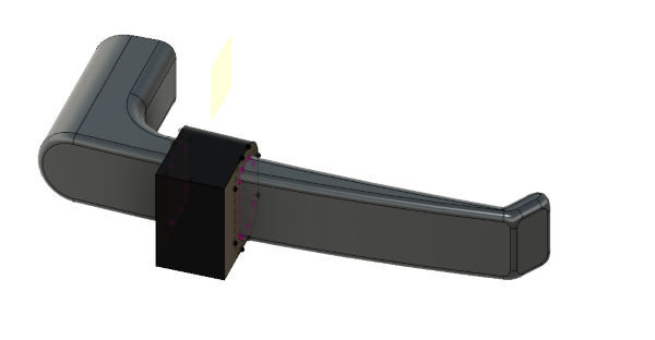
Created another sketch from the top and extruded it with the intersect mode so that it cut the bumper body to a taper. The bumper only needs to be wide where it contacts the wall surface.
Added fillets to all edges of the bumper. It looks better, is stronger, prints better and makes it less likely to damage the wall on impact.
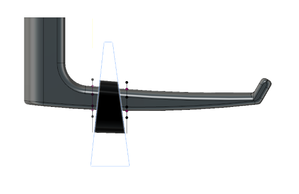
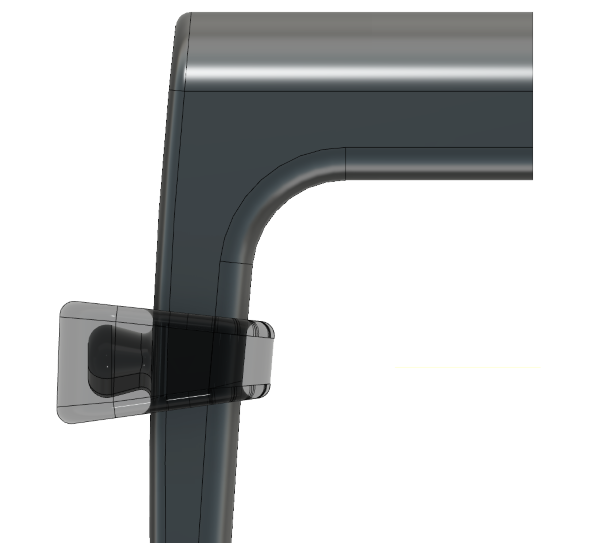
At this stage the bumper could still be milled 2-sides using a 3 asis mill. So I looked for reasons to make its geometry more advanced. I decided to give it an inside hollow that would be impossible to reach with the 3 axis mill and that might change how the bumper compressed when hitting the wall.I did this by adding a sketch to the inside face of the bumper and cut-extruding outwards with a 15 degrees outward taper angle. Shown below in 75% opacity.
As usual I added fillets to all sharp edges.
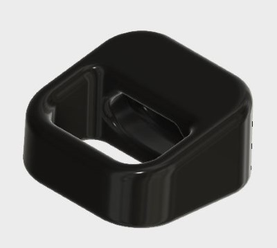
I edited the sketch to give the opening to the internal cavity a flat roof (that the 3D printer can bridge) to avoid "noodeling" with this soft filament.

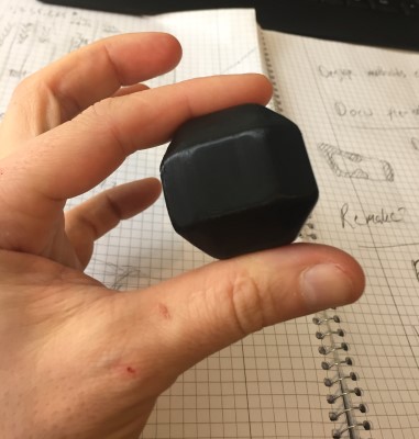
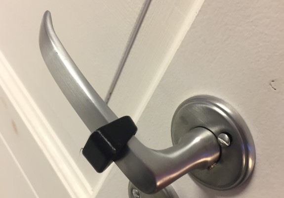
I printed it using the same settings that I had tested out before.
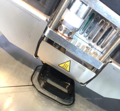
It fits fine on the handle! It performs OK as a bumper, I think I could have used thinner walls or less infill to make it even softer, it is a bit too hard to be optimal but works!
UPDATE: 123D Catch has been discontinued by autodesk and replaced with Autodesk Remake. All my experiences are from using 123D Catch and may or may not apply to Remake.
123D Catch is a smartphone app from Autodesk using a series of pictures to generate a 3D model. This 3D scanning method is called photogrammetry. Which in practical tearms mean that you take pictures all around the object you want to scan and the computer tries to create a matching 3D model based on how the object looks different in the photos from different angles.
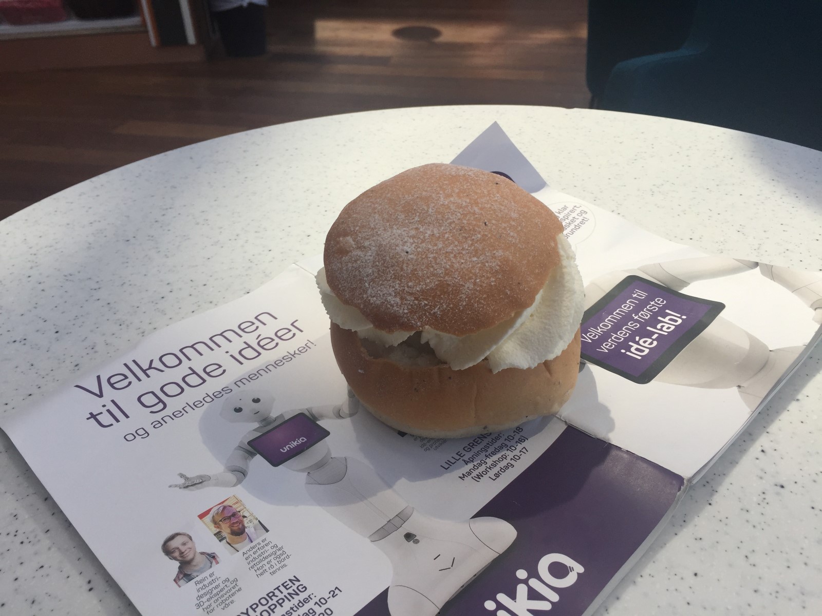
While I was traveling to Sweden I took the opportunity to try and scan a bunch of different objects around the airport. I tried a luggade trolly, a high chair, a coffe cup, a chokolate pastry and got really bad results. Most likely due to a combination of the objects being shiny and me not providing a good enought background or enough photos. I finally got a good result with a local traditionall pastry called Semla. I put a magazine underneath to give the software more reference points it as I had seen recommended in this video.
My delicious semla! Whilst being scanned.
The resulting textured 3D model.
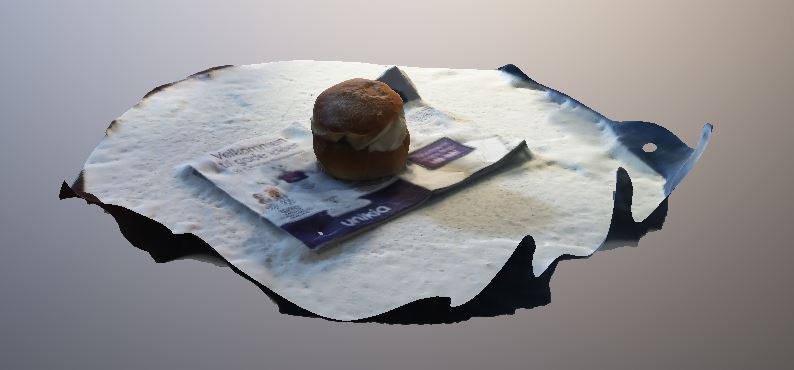
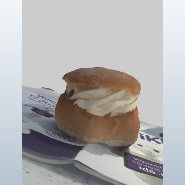
Semla pastry in .stl format scanned with 123d Catch
Verket Fab Lab is equipped with a wheeled structured light 3D scanning setup. It is based on a rolling frame with a desktop computer (for the GPU power) running the DAVID 3 scanning software. It has an height and angle adjustable tray with a commersial projector and a webcam. The operator moves the rig around the object and stops to scan it from many angles. Many other structured light rigs are stationary and instead move the object on a rotating platform.

.jpg)
Odd-Egil, the creator of this scanning rig gave me and Hanne a guided walkthough of the scanning process. I was the model for Hannes scan and I tried scanning a manakin hand. We both practiced the cleanup and exporting on my head-scan.
A 90-degree calibration screen is used to calibrate the software. The web camera will find the dots printed on a paper glued to its surface and the know 90-deg angle will be used for calibration. The screen is placed at the distance you want to scan from.
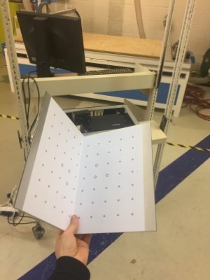
David uses the projector to project a test pattern onto the calibration screen. It monitors the resulting projection through the webcam and compensates for any distortion and angle between the camera and projector.

When it is calibrated David uses the projector to project a perfect chess pattern on the inclined planes, with the squares meeting at the points printed on the paper. This represents the calibrated "scanning window". The size of the clibration screen determines how large each scan can be, so in order to make larger scans you need to first make and calibrate with a bigger screen. Using a window not much bigger than your object helps reduce noise.

This is me bing scanned

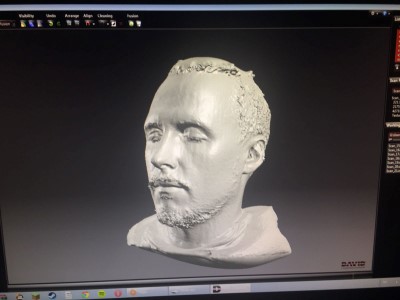
This is the model after merging the different angles together.
Having good settings when scanning helped us generate less noise.
I imported the obj-files into Rhino and started removing stray "blobs" to make the model more useable. I have not yet printed the model but I look forward to doing so later.
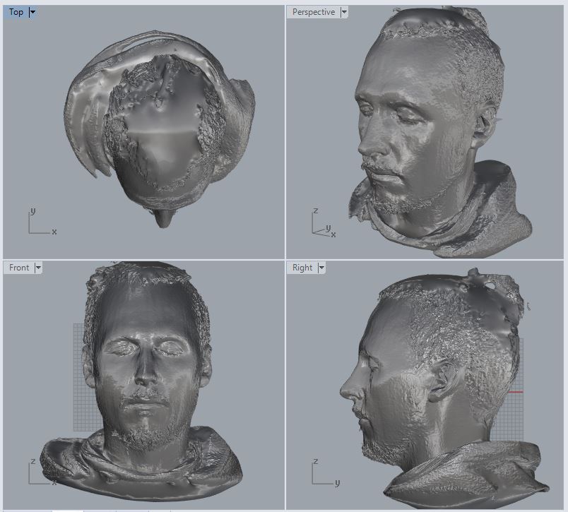
Note that the top of the head looks like there is ice-cream melting there, it is due to lacking image information and could have been mitigated by taking more shots from high up.
I'll keep working on the head in rhino, I hope to print it in the same flexible material used above when I have more time!
I like the idea of always having access to a basic 3D scanner in my pocket (photogrammetry apps) even if the models probably will not be of a super high quality.
I am impressed with the quality of the fused mesh we got out of David and I like the "hacked" setup using a commercial projector for the light patterns. However the process is quite slow and the models still needs quite a bit of cleaning. I would like to try an even more automated setup.
I think 3D scannning is most useful for copying, storing or referencing complex organically shaped objects like body parts, natural shapes or sculptures. When it comes to creating a 3D model of machine made objects I think it is usullay smarter to just measure the object and CAD the relevant parts anew.
Example: 3D scan a crumbling ancient statue so that its shape is preserved digitally.
Example: Measure the size of your circuit board that you want to design a case for. Scanning and cleaning the scan will take longer and you will get more precise measurements with calipers.
I like 3D printing, it is a great tool to have in my repertoar. It is not a one-stop-solution but has really good uses. It is also very statisfying how fast you can iterate evaluating a printed model, change it in CAD and print it again to see if your changes had the effect you thought it would. This iteration usally takes much longer and this slows down learning. I recommend 3D printing as a good tool to learn CAD together with.
Pros:
Cons