It's easy to think about building something super-cool
as far as you don't have to make it
Maybe a mini vacuum cleaner or a long blond hair humanoid... Maybe a spaceship or a time-travelling machine...
Cool yeah?
Yeah, that would be great to be shown in your portfolio but when you start with very little knowledge about 3D design and none about
embedded programming, what you really aim to is improving your skills and make something working...not just to be the cool-one.
As you go deeper into a project idea,
you have to face with your actual abilities and with their limits and in a second you drop off from your spaceship to a very simple
3-axis something.
That doesn't mean 3 axis means low results: large part of the most useful and widespread machines work on x, y and z, so just respect state of art and
built something that won't make you feel ashame.
First Idea
As soon as Chiara Corbo and me
formed a group, we started thinking about something we could
realized, given our low skills in programming ( that part was the most abridging one).
First thing that came to our mind
was an interactive wardrobe that should pull down and push out your shirst as you select its row. After spending half a day on sketching it down,
we soon realized this project had main problems:
- room needed for a extendable bracket;
- structure dimensions;
- material costs
So we discarded that idea and git back with empty minds.
Inspiring Tiger
When first idea fell apart, Chiara Corbo
and I started blasting away unattainable ideas but in the end we
just couldn't find something nice to develop. So, Chiara Corbo
suggested to have a walk around
(Siena can be really inspiring in sunny days ;) )
and hers
revealed to be the greatest proposal she could ever made. We went to Tiger and something caught our attention:
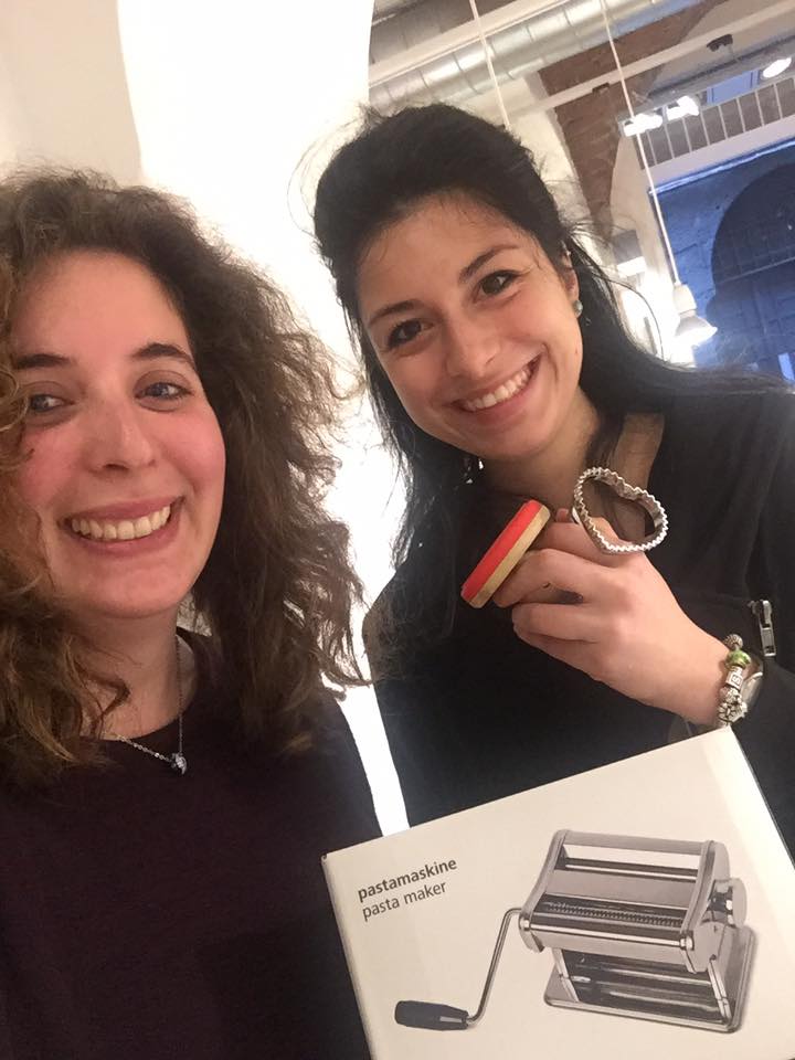 Yeah, you got it: we wanted to make a BISCUIboT
Planning BISCUIboT development
Nice name....but what the evil is it for?? BISCUIboT is a very simple system
that is intended to level off your short
pastry and to cut rows of biscuits out.
Therefore it looks like a 3 axis machine:
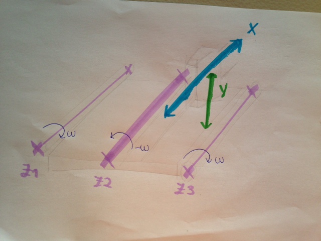
 With Chiara Corbo, we sketched the shape of the machine easily on paper:
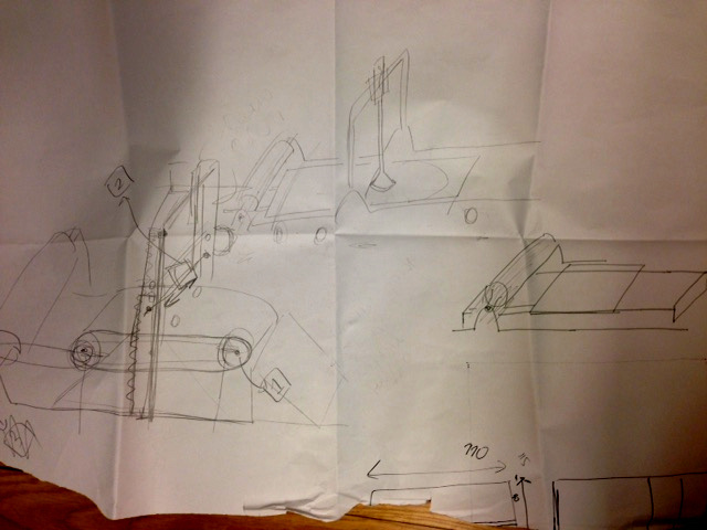 (This scambled-looking drawing is just intended to show initial chaos about project features ;) )
We then agreed that owing to our several university commitments, that this week I could take on the greatest part of the
design. Anyway, she gave me great help with biscuits
ROLLERS
If the first issue didn't scary me that much at this point,
I still had to design the rollers in a suitable way for winding cloth ( or whatever I would made belt of ) and slipping it.
After a first attempt saw them shaped like sharp gears with an intention to 3D print them but I then realised this would have:
- made their tips fragile
- hindered a smooth and continuous dragging
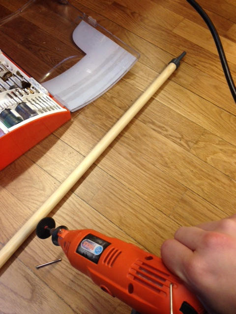
I so decided to use a wooden pole of 18mm diameter. Why 18 mm? Because the material I would like to use for lateral components and board
is 18 mm height wood, so, having a pole of close diameter can help dragging ( no height detachment = no sliding obstacle).
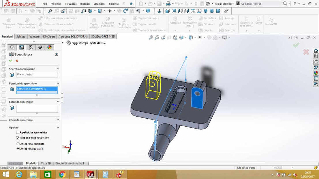
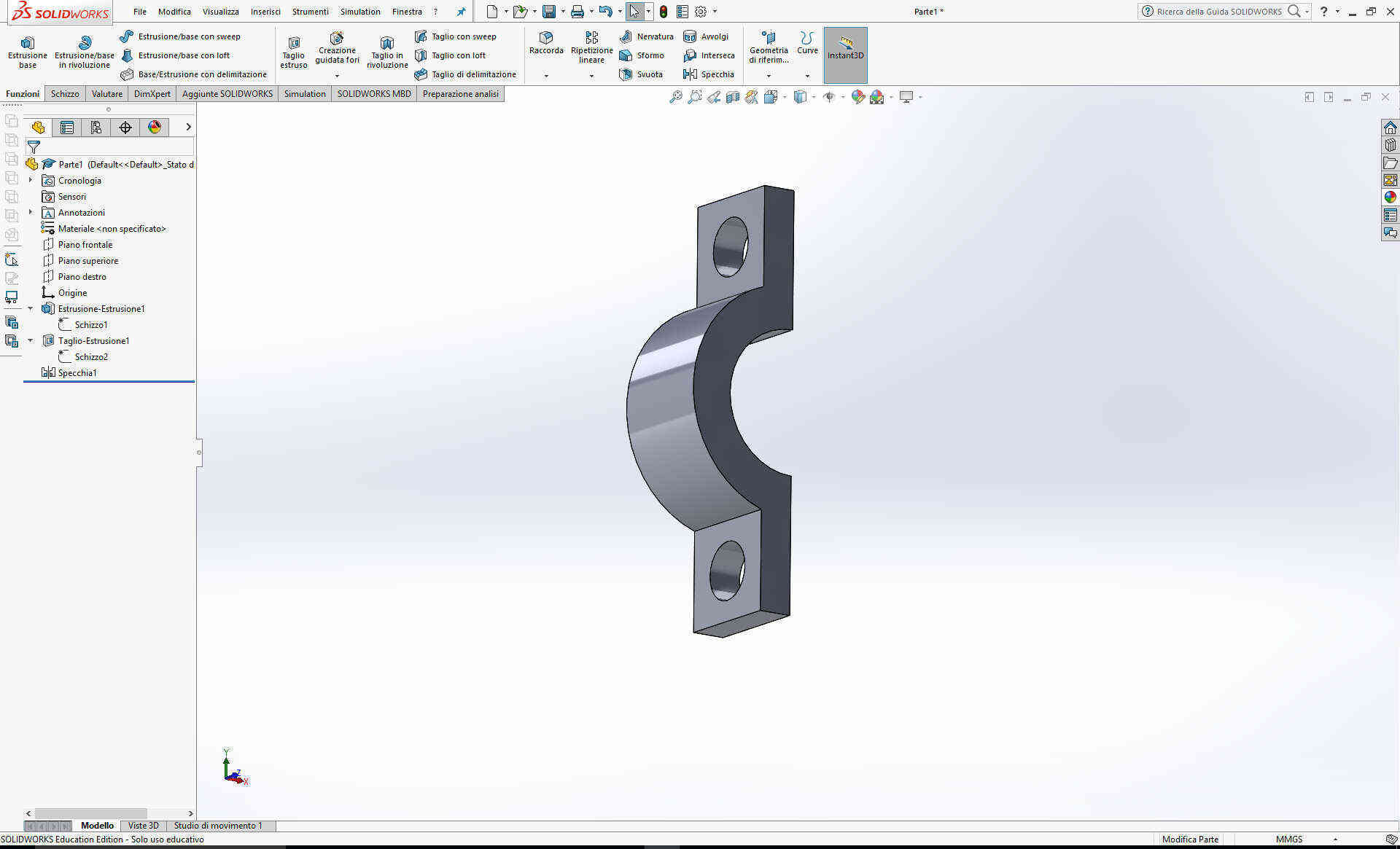
I so needed pole-bearing(internal diameter: 8 mm) and pole-
pulley converter.
My designs looked like that:
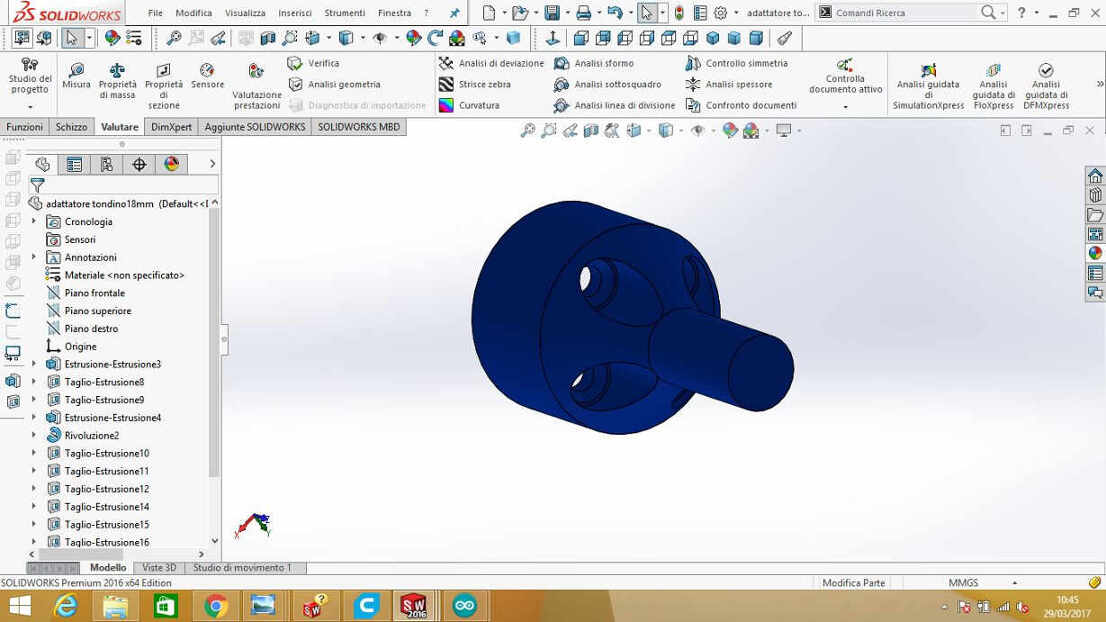
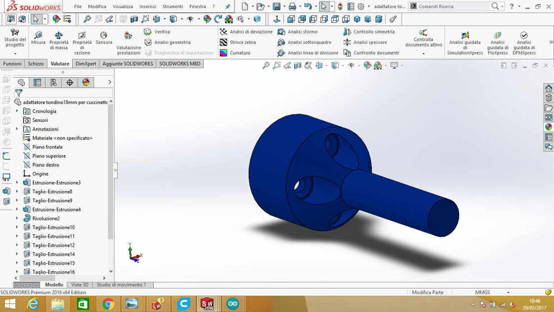
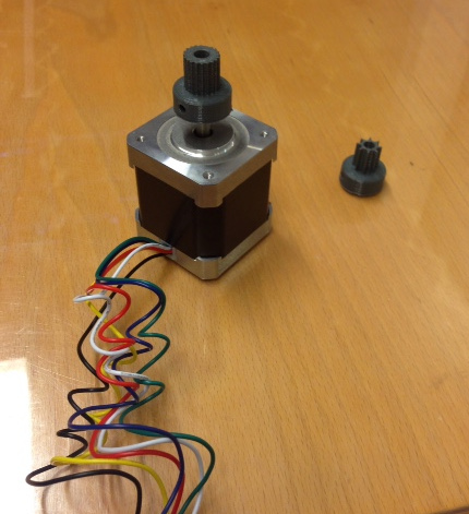
 NB: the last one is for NEMA 17 motor.
The intention is to stick part of GT2 belt onto the poles and sew another part in the inner side of the conveyor belt to make the sliding smooth and easier.
Similarly, for the rolling pin my intention is to use a 50 mm wooden pole if I can't find one at home - I can't 3D print it not only because it is
quite high but also because I need it heavy.
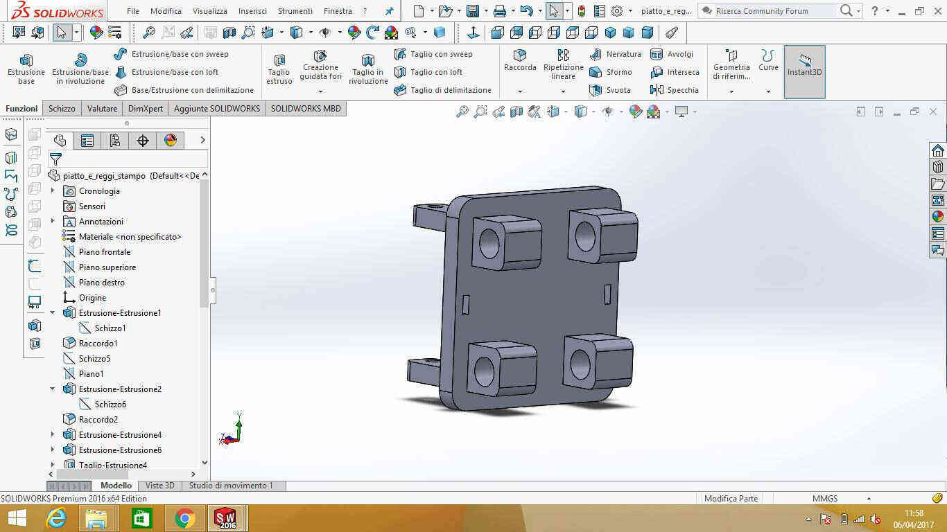
CART
Another problematic point of my design was mold-holding cart. I would have liked to use just a motor to move it both up-and-down and left-to-right but I couldn't find
a compromise that could suit my design, withouth endangering stability and dimensions tightness.
As for shape, I took great inspiration from two students's machine
of FA 2016, Luca Giacolini
and Flavio Lampus: the
G00 x6000.00.
I liked a lot the GT-2 toothed inner cut of the cart
and I wanted to applied it to mine beside providing it with a suitable mold holder.
At first, I made weak mold clip and had no toothing in the internal cut:
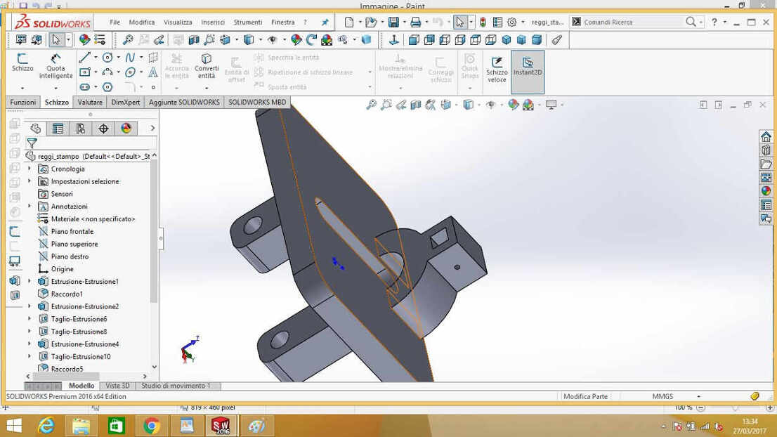 NB: notice that I made a single-direction blocking spot without considering that this coul create a torque in the other direction.
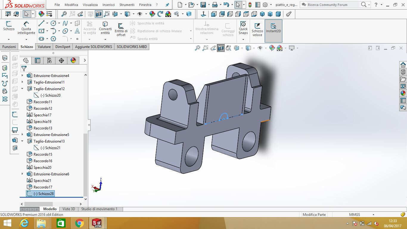
I so made a more robust holder:
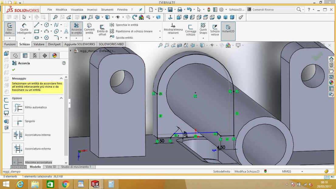
 Before grabbing it to the cart, I wanted to round inner cut edges cause the pulley had a larger diameter in the upper and lower parts of teeth, which showed an angle
NB: there's a big mechanical error in this procedure that I will explain below so dont trust first following steps!
 I so went through Functions-->Fillet and selected upper edge and then I repeated this action for the lower one.
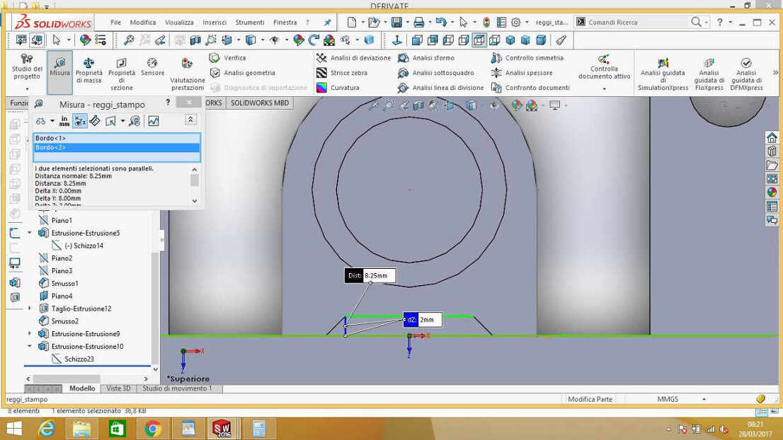
Only
after that,
I could design mold-holder connection:
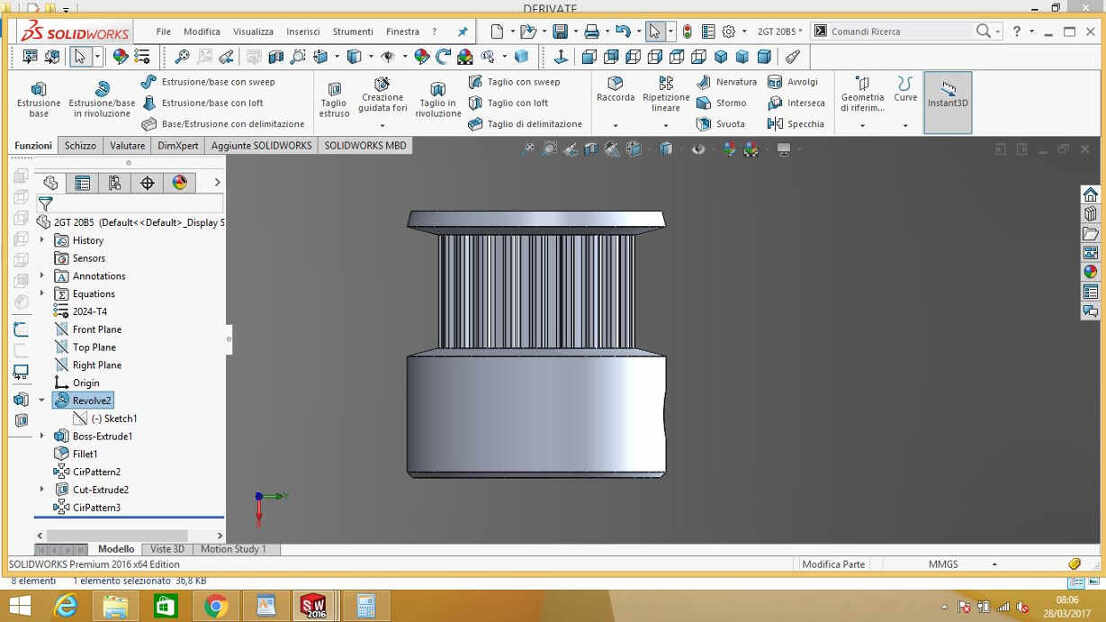
 To see minimum height I had to leave from surface I first checked on pulley design:
 I then extruded it:
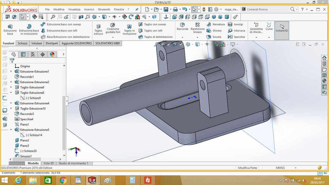
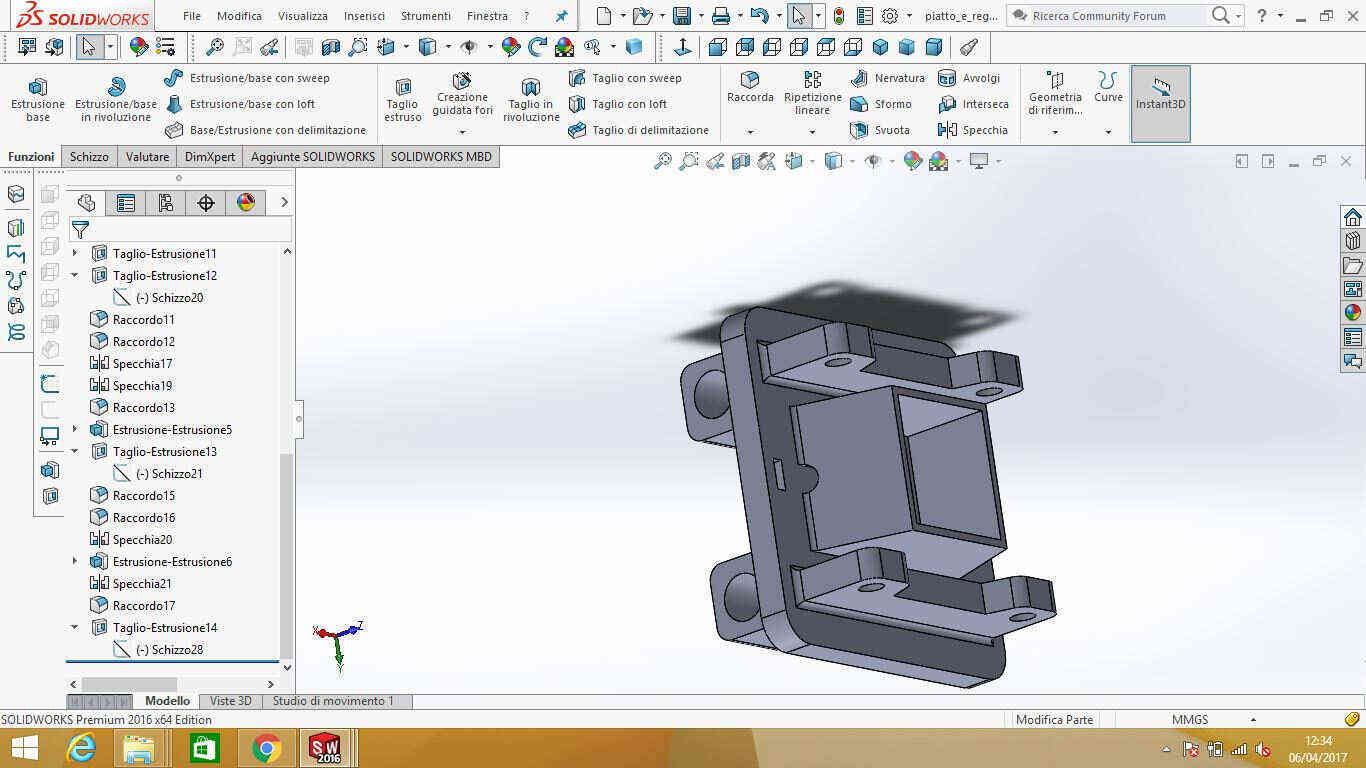
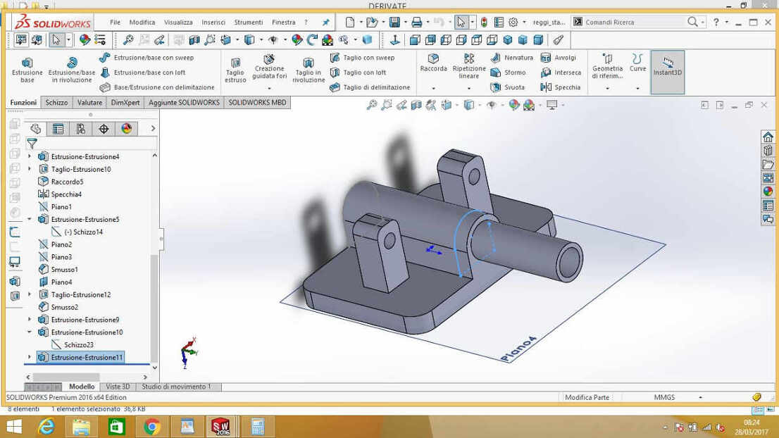 In the end my cart looked like that:
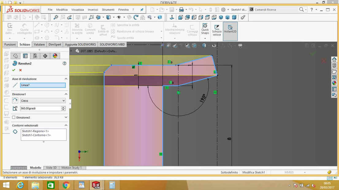
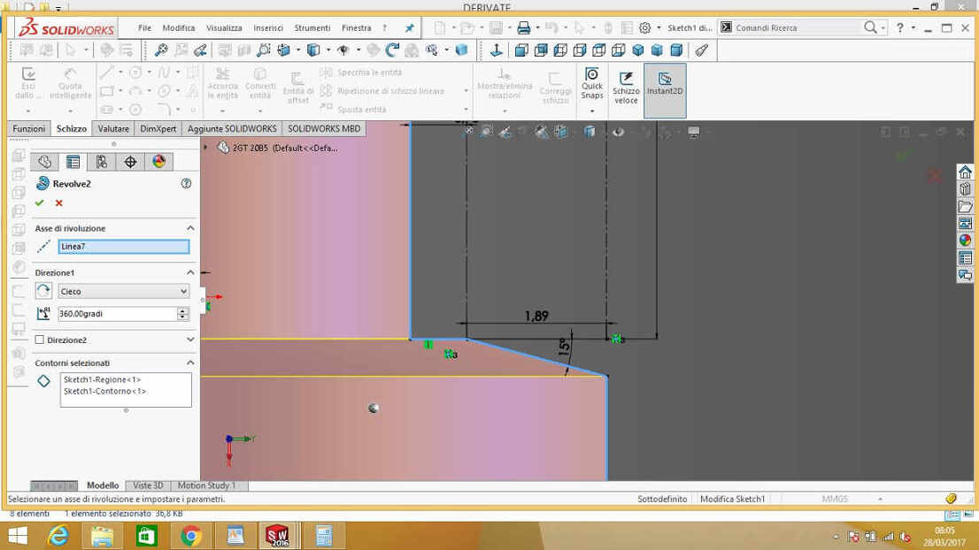
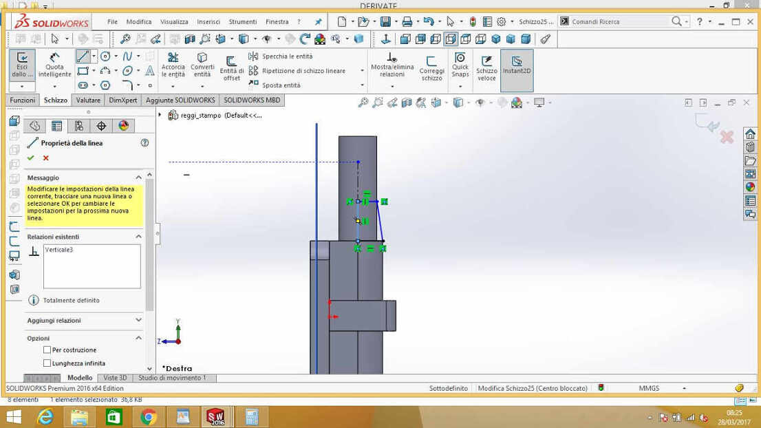
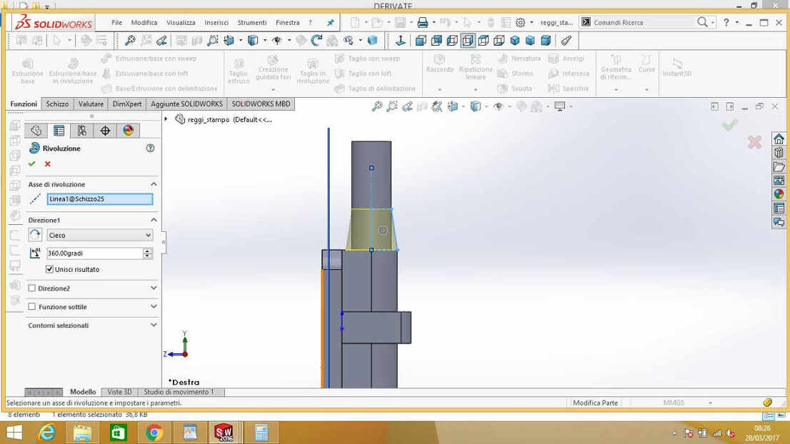
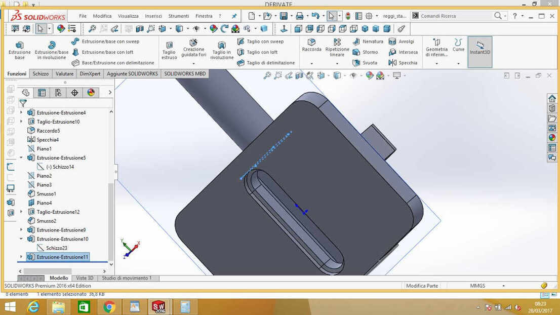 I mellowed edges with a sketch revolution:
 ...and added proper holes from m3 screws (to be placed identically on mold) so as to block the part.
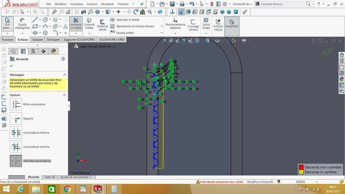
I now had to add toothing to cut inner surfaces, whose height corresponded to pulley slot area height.
Maybe I just couldn't type right words to find on the internet because I found no help, but I realized that
basically I needn't to have teeth in semicircular surface, toothed sides would have been enough for movement
transmission (save practical experience wouldn't deny it).
I so looked for GT-2 basic unit sketch
in order to use Mirror function in sketch tools.
To copy a sketch and paste it into another part you have to:
- 1 - open sketch you want to copy;
- 2 - select it in Feature tree;
- 3 - go through Edit-->Copy;
- 4 - pick part of interest in another part;
- 5 - go through Edit-->Paste;
and we then agreed that owing to our several university commitments, that this week I could take on the greatest part of the design. Anyway, she gave me great help with biscuits
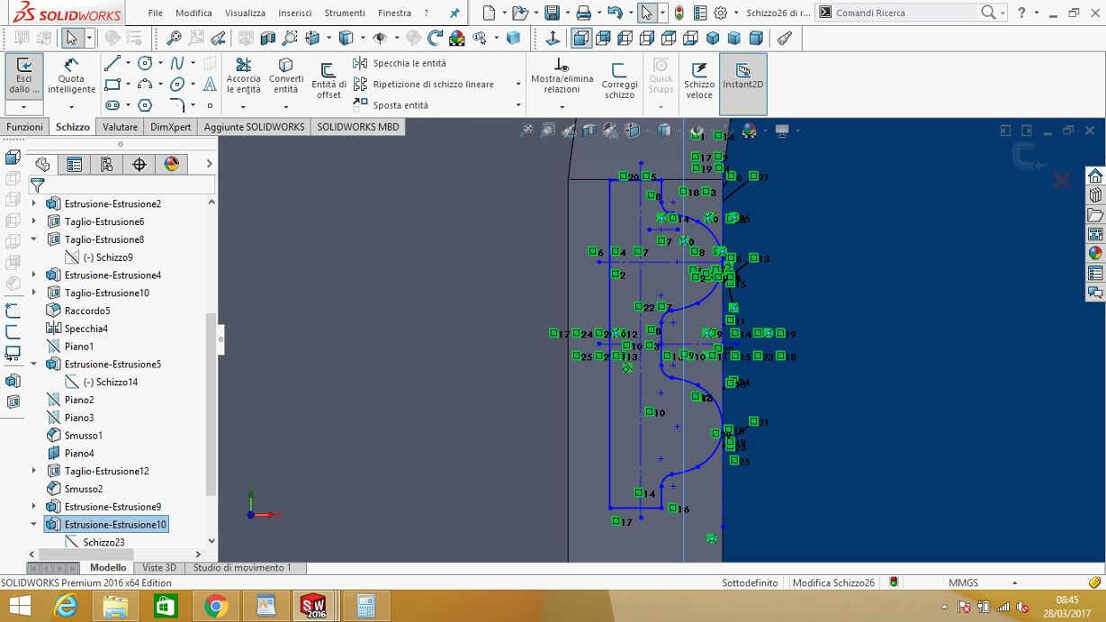 I then used Mirror tool until I covered all the surface:
ERRORS
There are two mistakes I care witnessing in previous screenshots are:
- wrong side mold-holder;
- pulley-integration impossibility
For the first one, there's no much to say: KEEP CALM AND SKETCK HARD.
 After Chiara designed the mold, I made two holes for screw-blocking in right position.
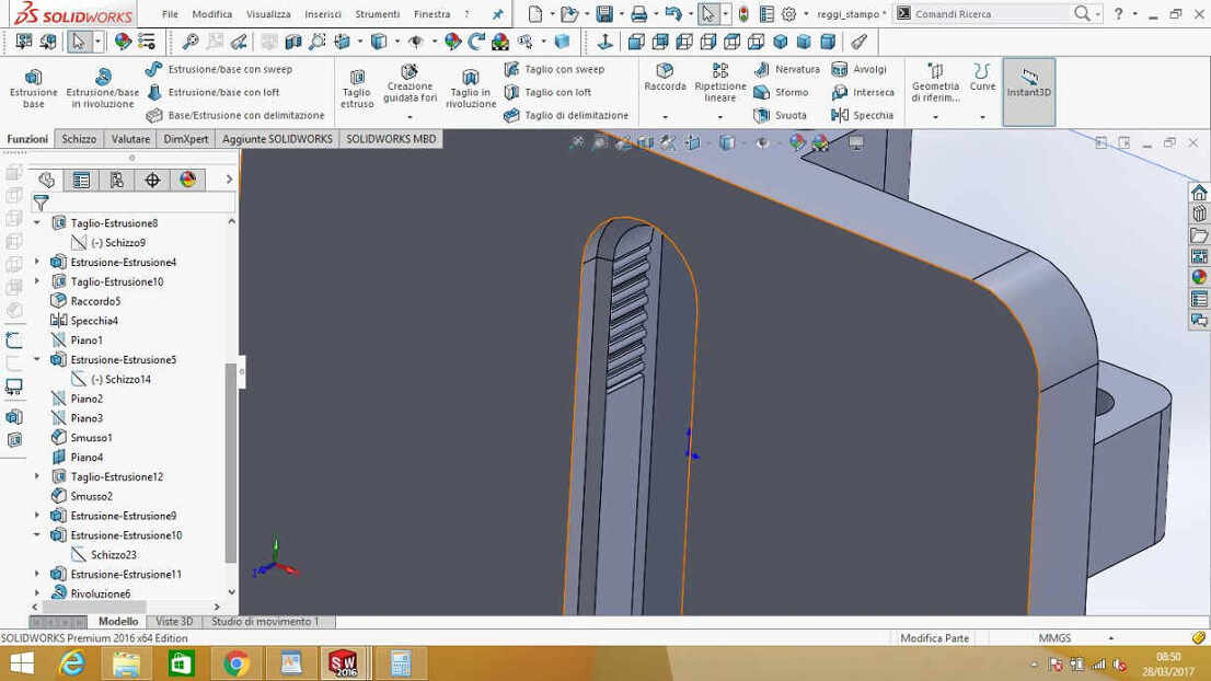
For the second one, there's less immediate evidence: to see the problem you have to imagine inserting the pulley into the cut of the cart.
If you focus pulley shape, you'll soon understand that there's little need in upper edge rounding cause the upper part of the pulley
is larger than the space I left between two teeth rows, so there's no way the pulley can enter its position.
Anyway, the easiest solution
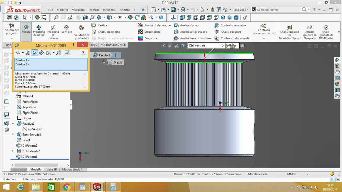
I found consisted in using a different pulley shape, with no larger roof. To design it, I looked for GT2 pulleys
on Thingiverse. If you look into Apps window, under models slider, you can
edit pulley with Customizer app.
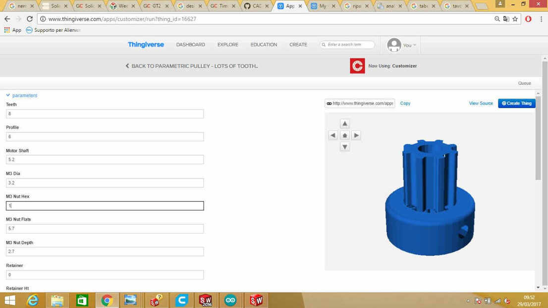 NB: in Profile voice you have to enter you pulley type number, written in README.txt file in .zip folder or
in models note on Thingiverse - in my case GT2 2mm corresponded to number 12.
NB: in Profile voice you have to enter you pulley type number, written in README.txt file in .zip folder or
in models note on Thingiverse - in my case GT2 2mm corresponded to number 12.
At first I tought that in GT2 mm, "2 mm" stood for bore diameter of the pulley so I chose GT2 5mm gained this result:
 which evidently didn't suit my belt size.
I then understood I had to take GT2 2mm pulley and I gave it 20 teeth and it suited my NEMA 17 well.
 NB: I still have to see if in practice my solution works well.
Design & Materials
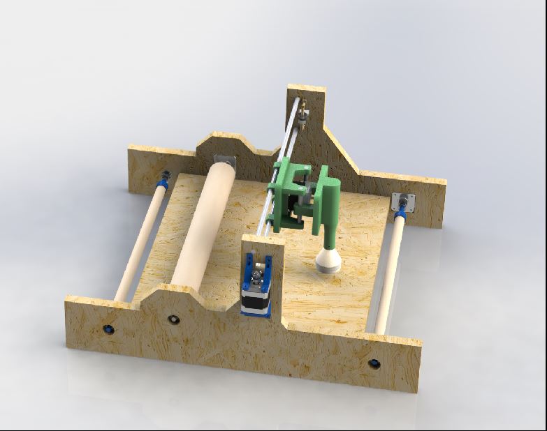
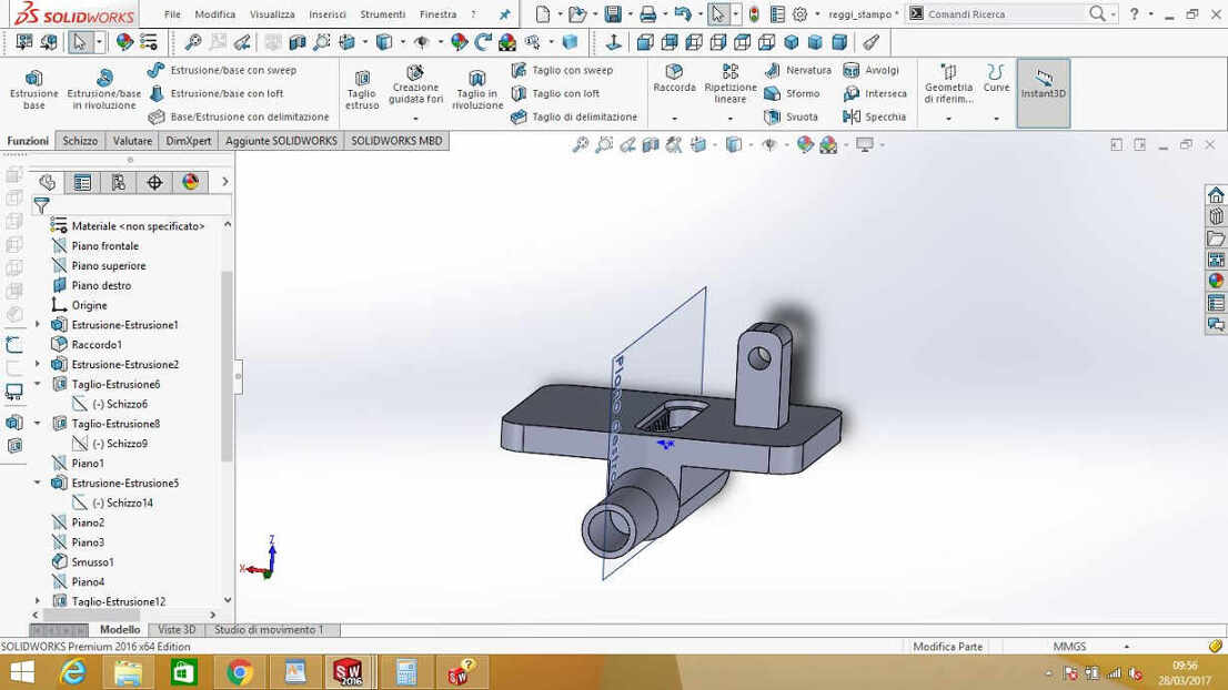
Other parts looked quite easy to be designed and making the assembly helped me in checking everything fitted well.
Result:
MATERIALS
Our plan is to buy the least material as possible. What we need is:
- OSB (or wood in general): for chassis;
- WOODEN POLES of 18 (2) and 50 (1) mm for rollers and rolling pin;
- 3 BALL BEARINGS;
- 4 NEMA 17 motors;
- GT2 belt 2 meters more or less;
- PULLEYS 3 of 5mm bore, 1 of 8mm bore and the one I made on Thingiverse;
- PLA to print connectors and cart;
- 8mm diameter BAR
You can find .SLDPRT files in Download section ( I promise to convert all file names and README in english soon).
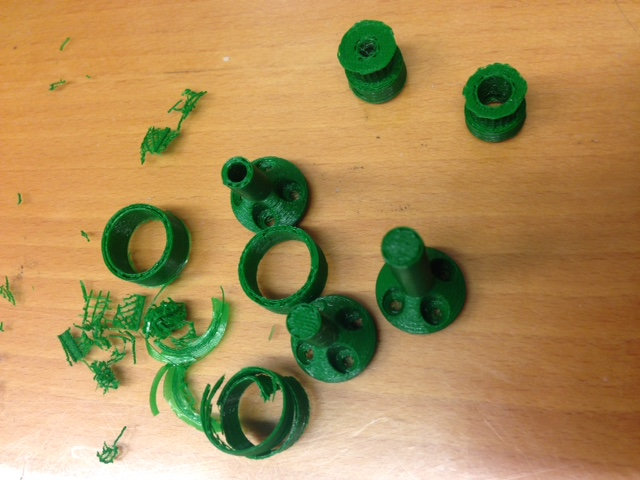
Printing tests
I started printing some components with very bad results:
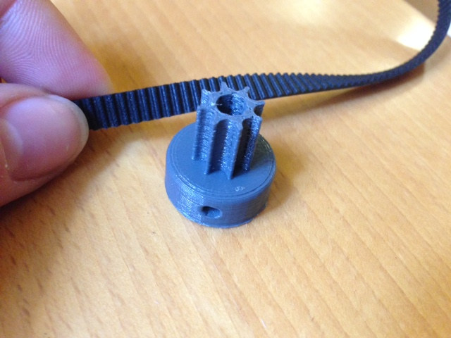
 PULLEYS were printed with 0.2mm layer height, 60 mm/s speed100% infill (from Cura) to be very robust but I didn't add touching-buildplate support, so the upper part
look very wavy and weak. Anyway, the joint with GT2 belt fixed well so it may be just an aesthetical imperfection - and if that doesn't make
the belt slipping over that won't be a big issue.
PULLEYS were printed with 0.2mm layer height, 60 mm/s speed100% infill (from Cura) to be very robust but I didn't add touching-buildplate support, so the upper part
look very wavy and weak. Anyway, the joint with GT2 belt fixed well so it may be just an aesthetical imperfection - and if that doesn't make
the belt slipping over that won't be a big issue.
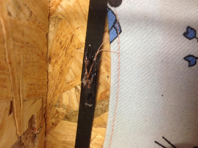
CONNECTORS: I used 20% infill with same speed and layer height values but the result looked so fragile that just holding tightly the
round-shaped edge to test solidity, I broke them. I could separate layers very easily:
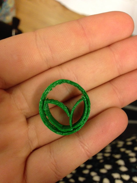 That made me think this was probably due to wrong filament extrusion settings.
Conclusions
Design took quite long to me cause it was a complex system to be developed due to my little (improving) skills but I'm quite satisfied
of the result. Also, I really like our project idea and I hope it could widespread as a nice home-cooking tool.
My intention is to cut, print and
join all components together in the next days and then I will immediately dive into motors programming aspect. I know that would be the
hardest part to me so I want to have time enough to work on it.
Update - 17th April 2017
Chassis cutting with Shopbot
First parts we need to start building with were two sides and board of the machine. We needed them to be quite heavy and stable so we rejected
lasercutting 6mm plywood and decided to use remaining OSB used in week7.
Chiara assisted me in milling procedure.
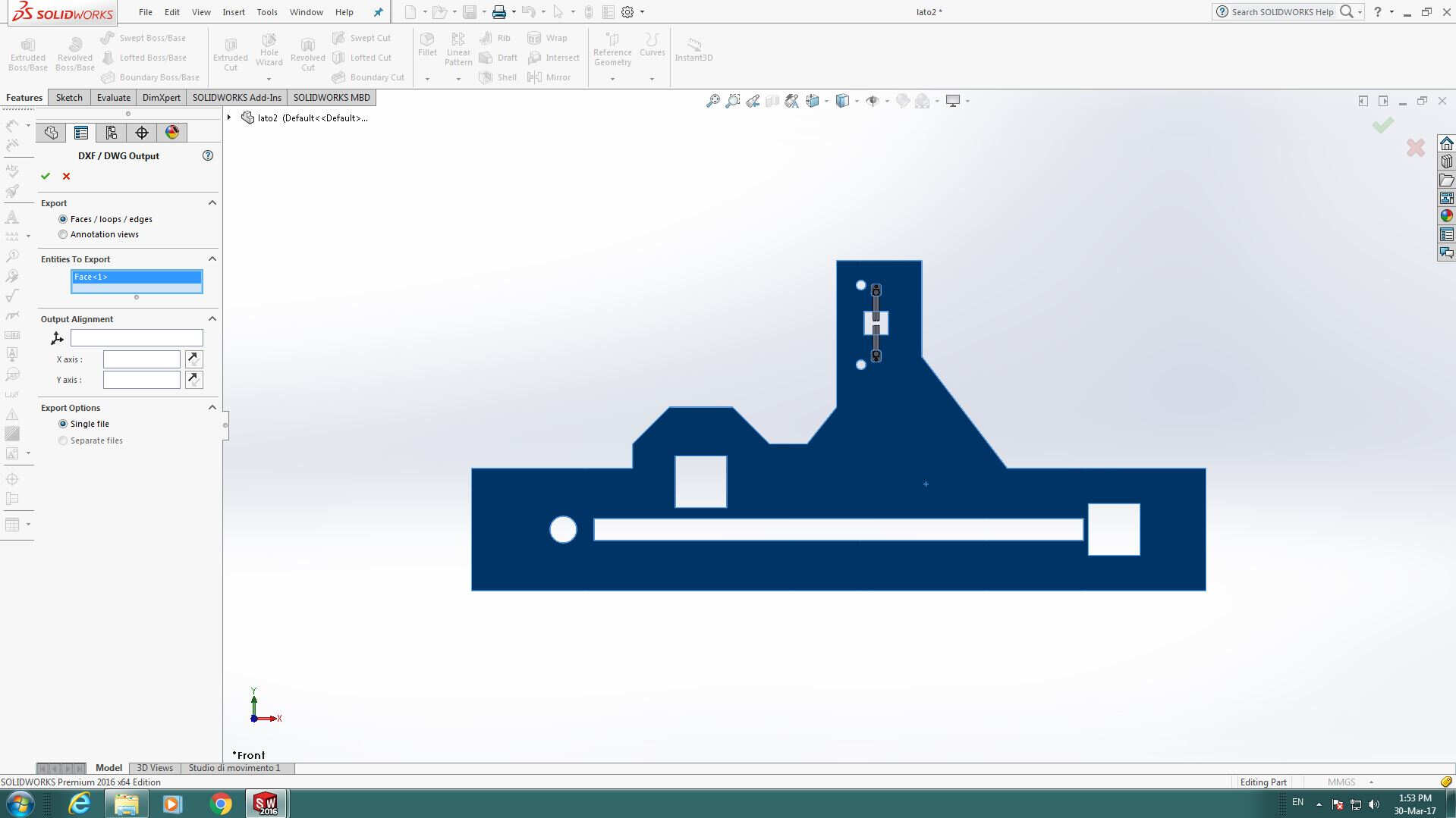
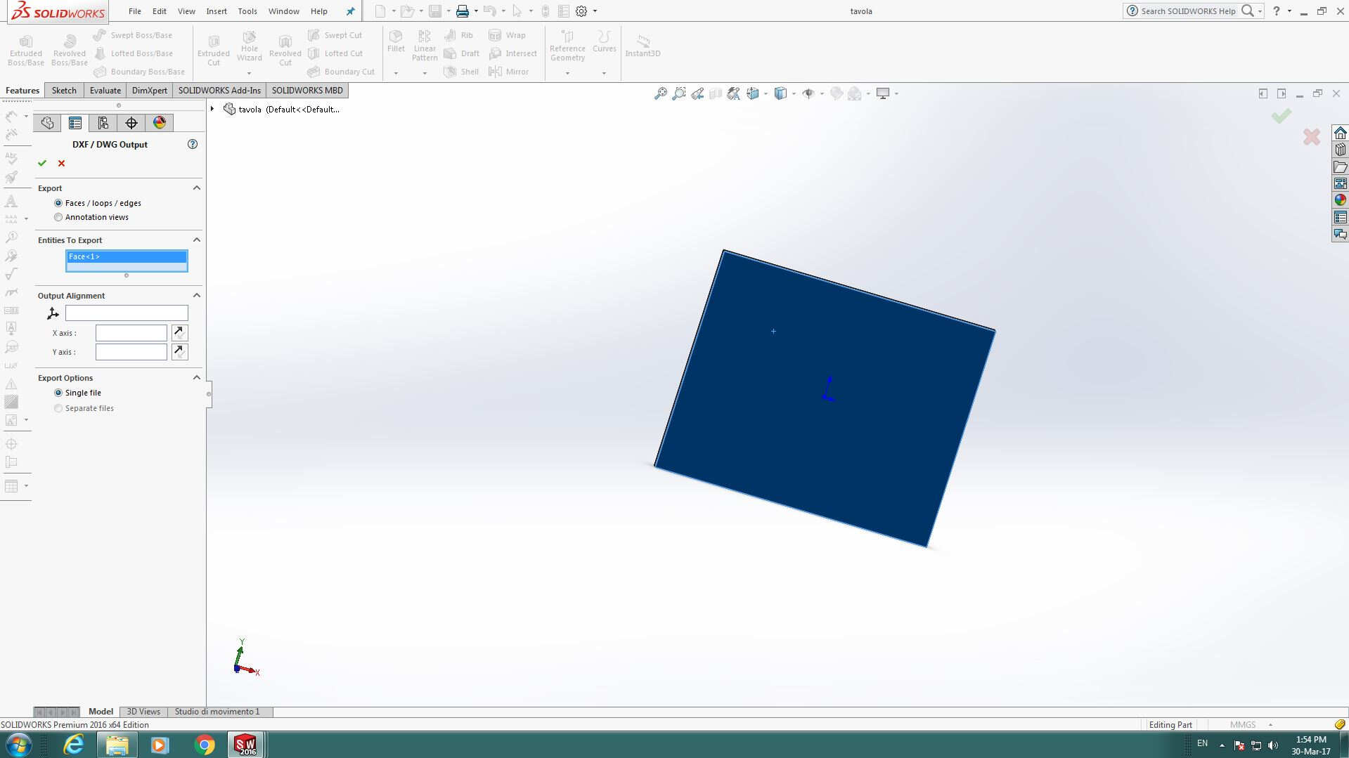
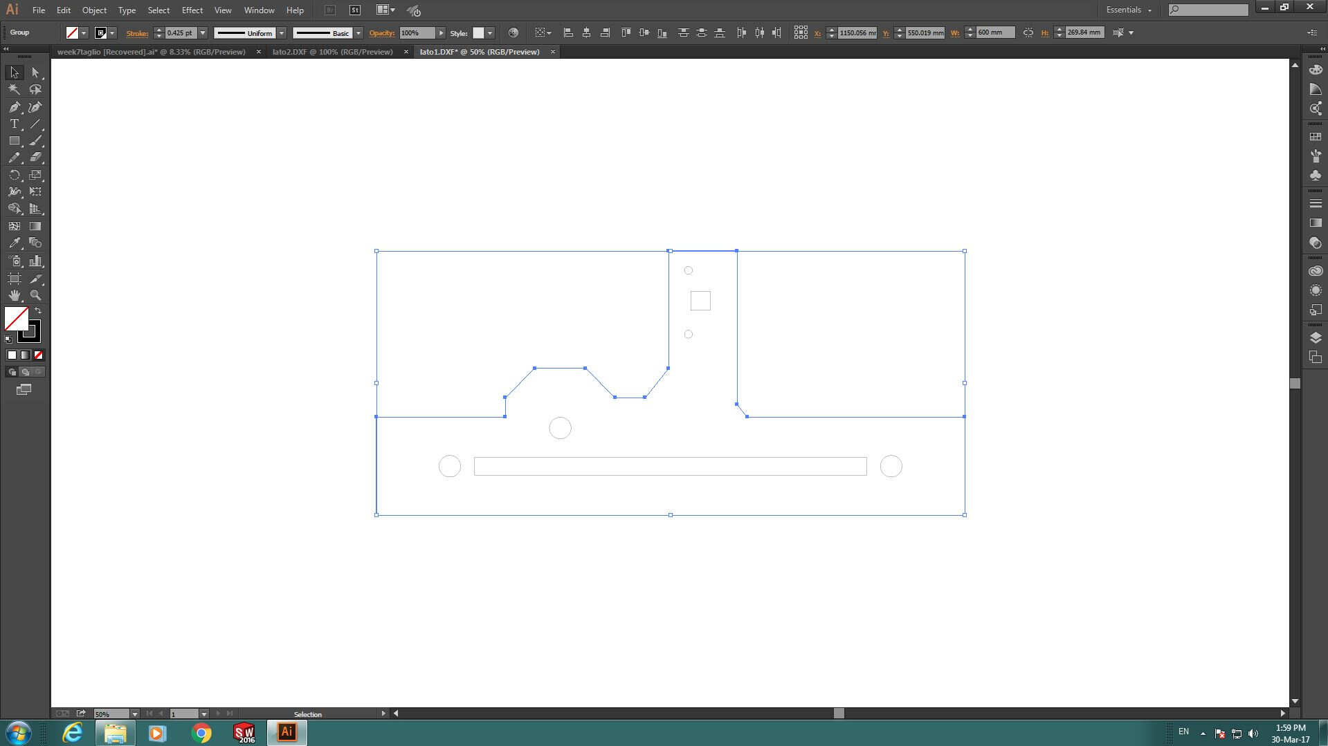
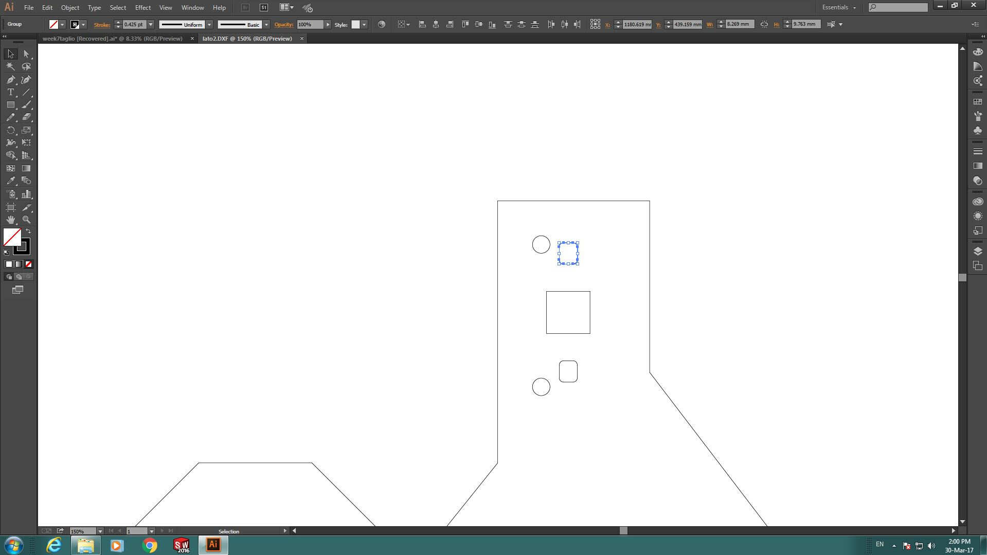
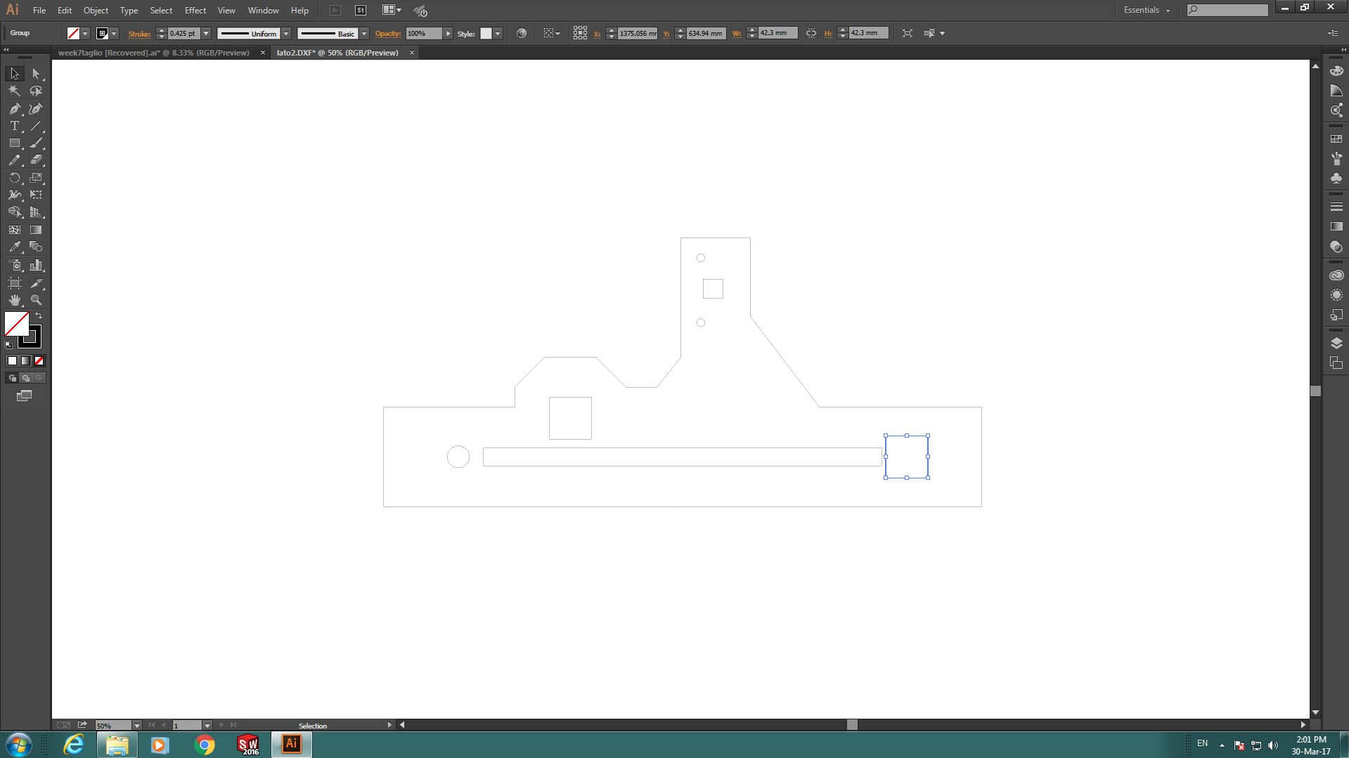
As explained in week7, I first of all exported
.dxf file of parts of interest:
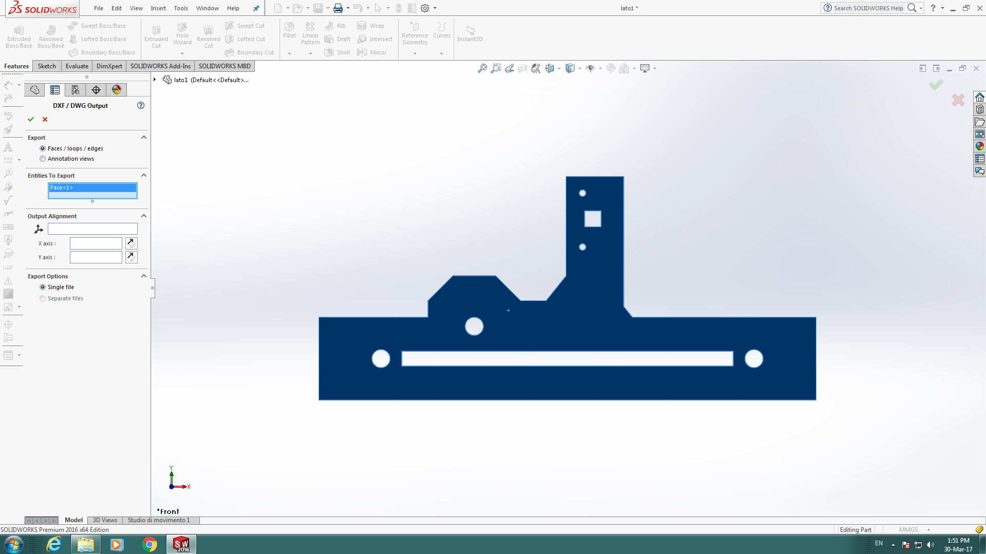
 Then I imported them on Illustrator
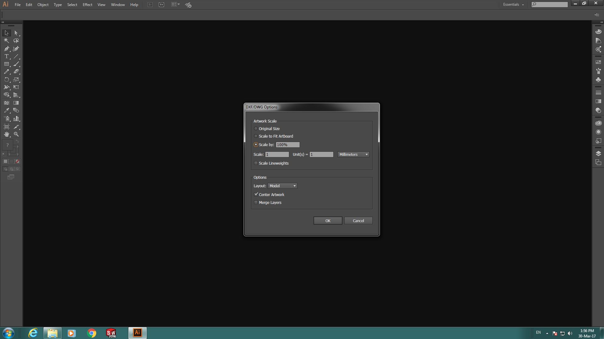 Used Ctrl+J commands to close lines
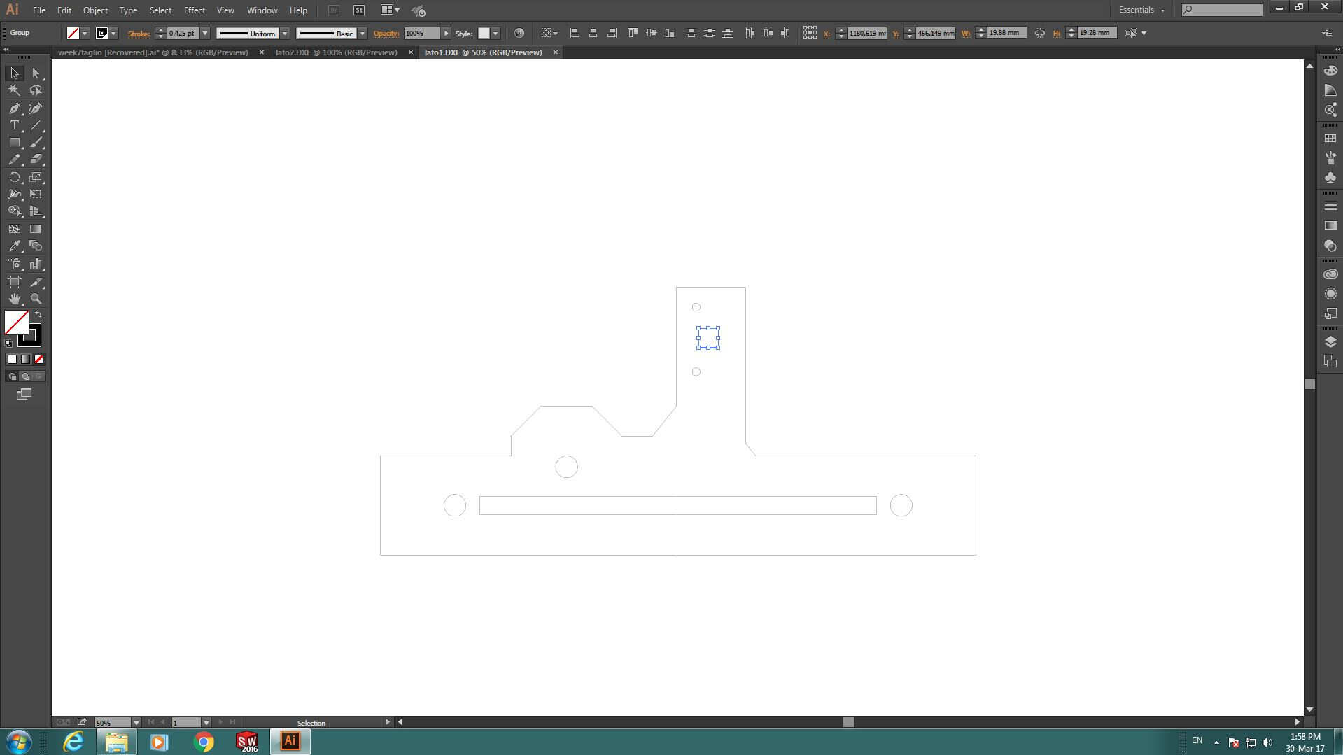
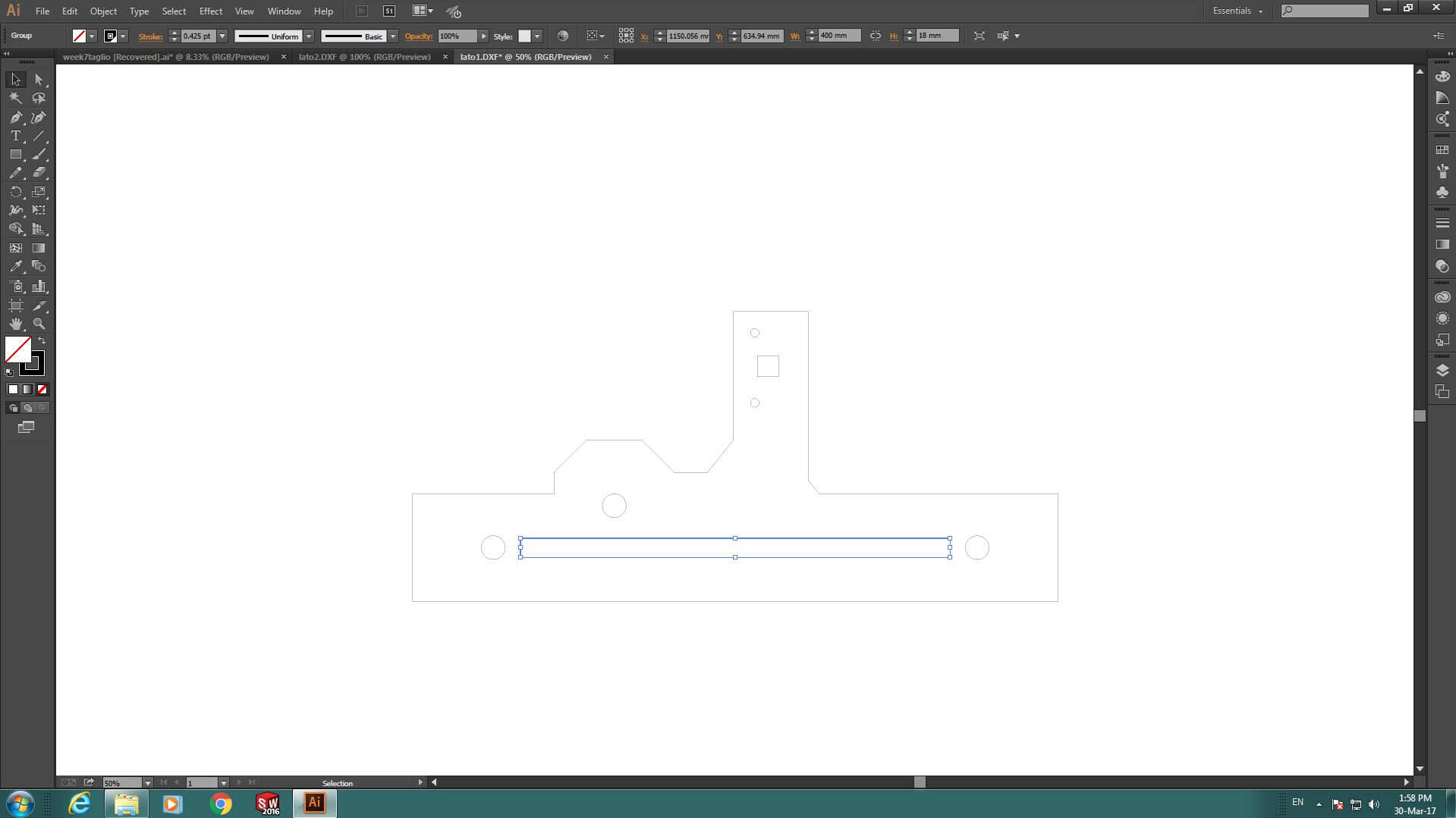
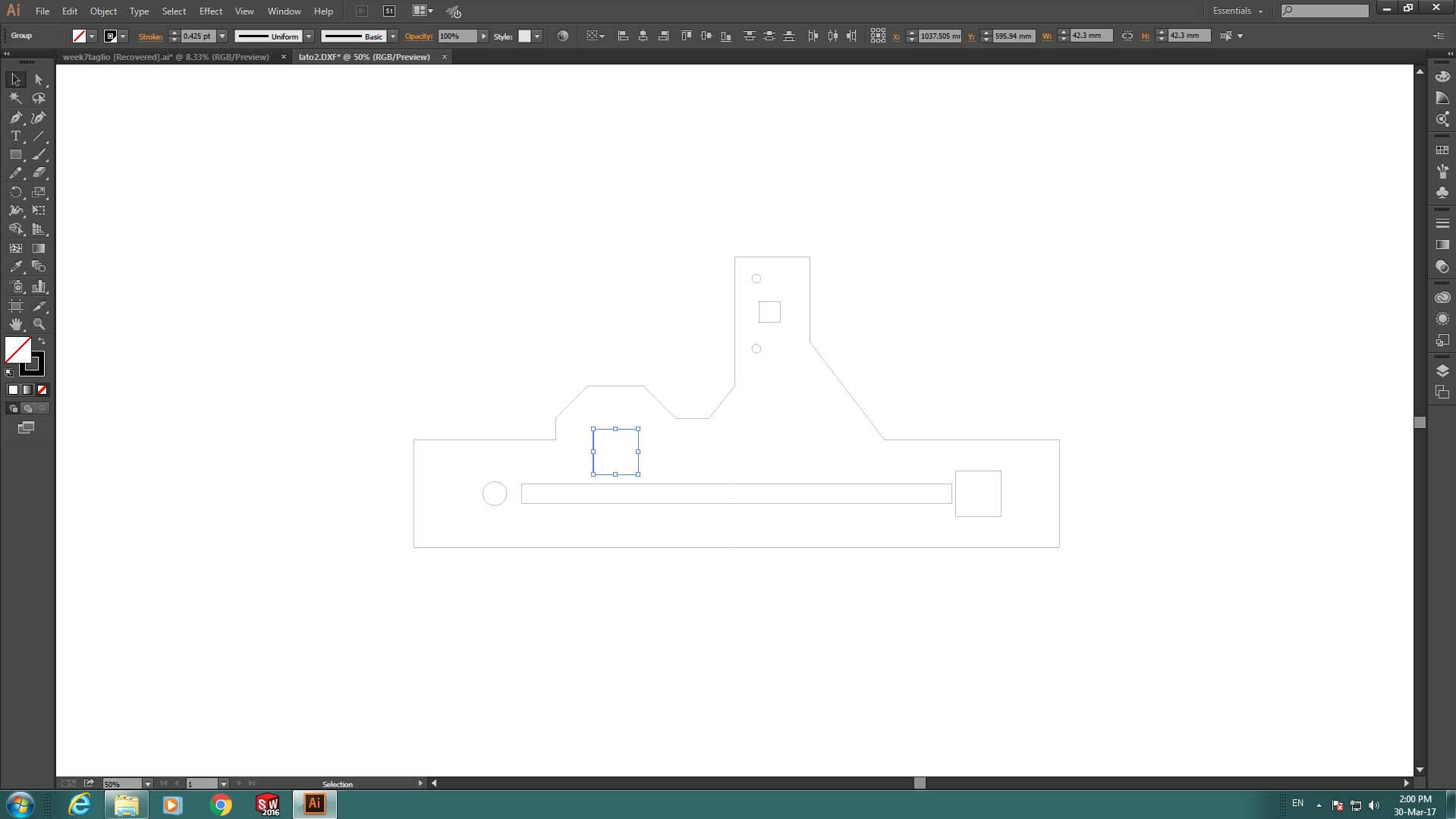
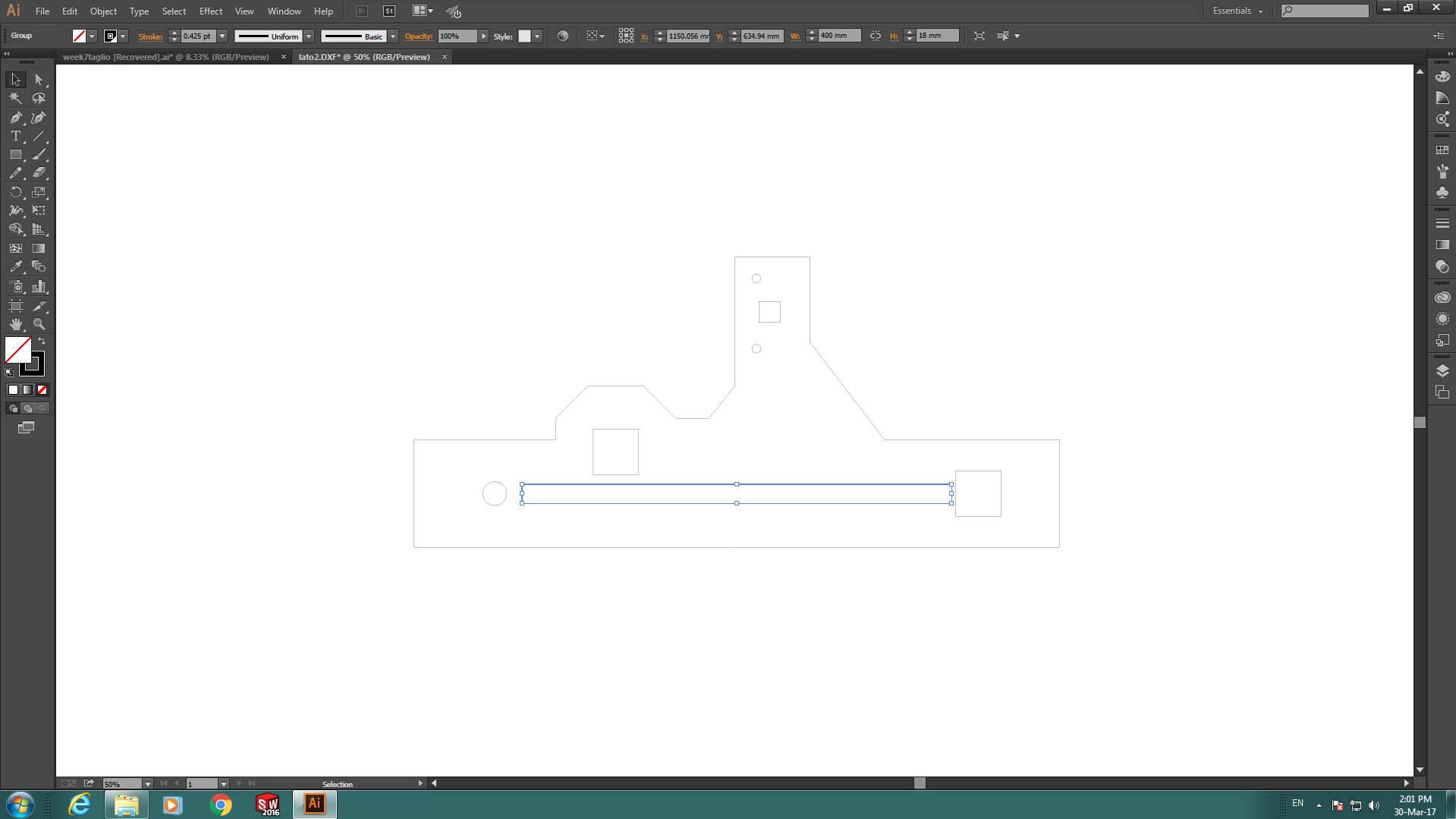
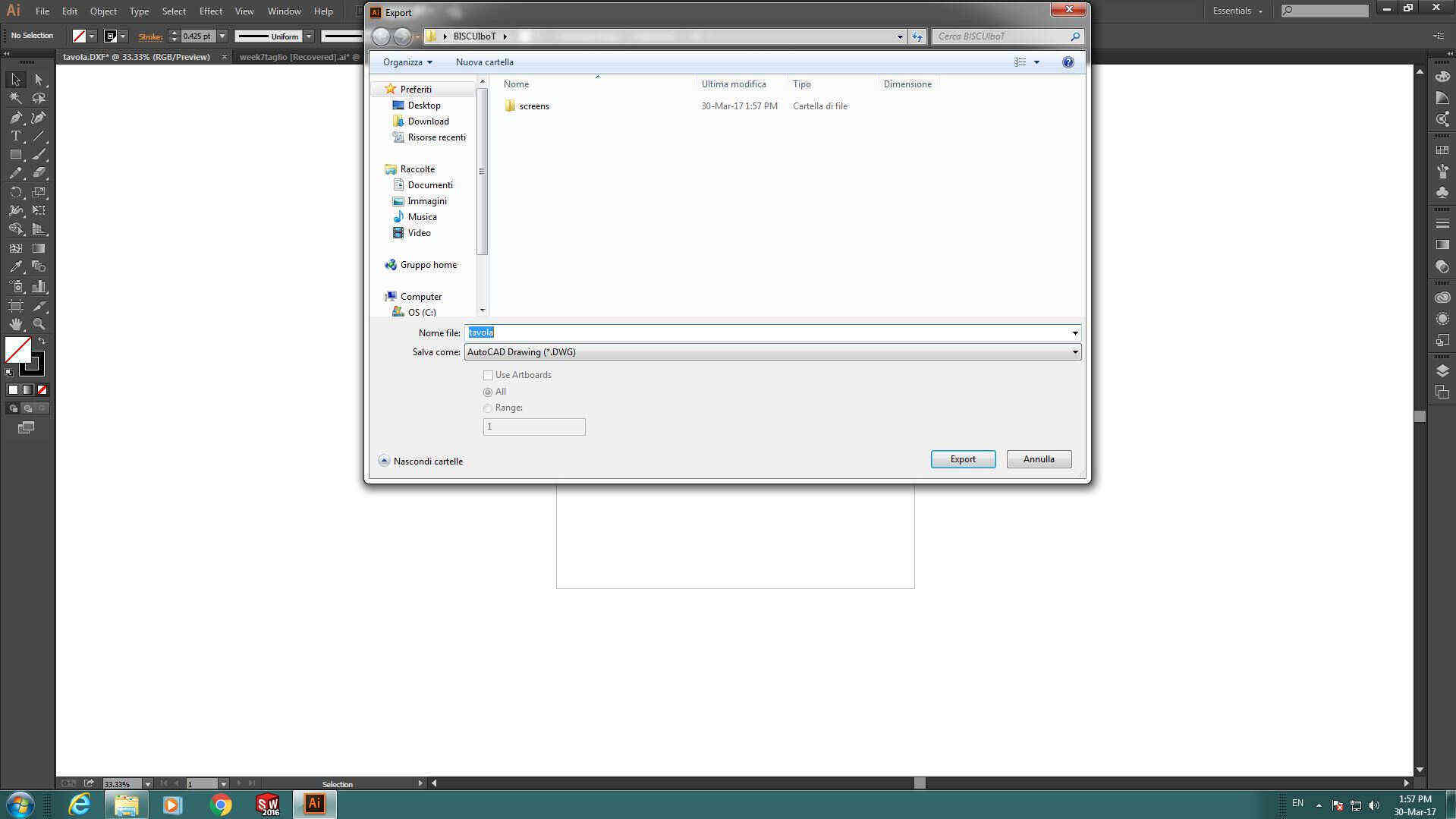
 and exported as .dwg file:
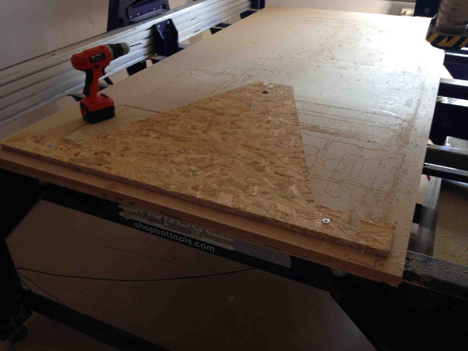
 I needed large dimensions pieces for the board and it wasn't so easy finding a large-enough panel to use: I ended
up with my instructor's trebuchet
testing panel and I screwd it to sacrificial MDF panel:
I needed large dimensions pieces for the board and it wasn't so easy finding a large-enough panel to use: I ended
up with my instructor's trebuchet
testing panel and I screwd it to sacrificial MDF panel:
 I measured available space dimension to set them on VCarve. I realised I had very little space left but I tought I could make it enter.
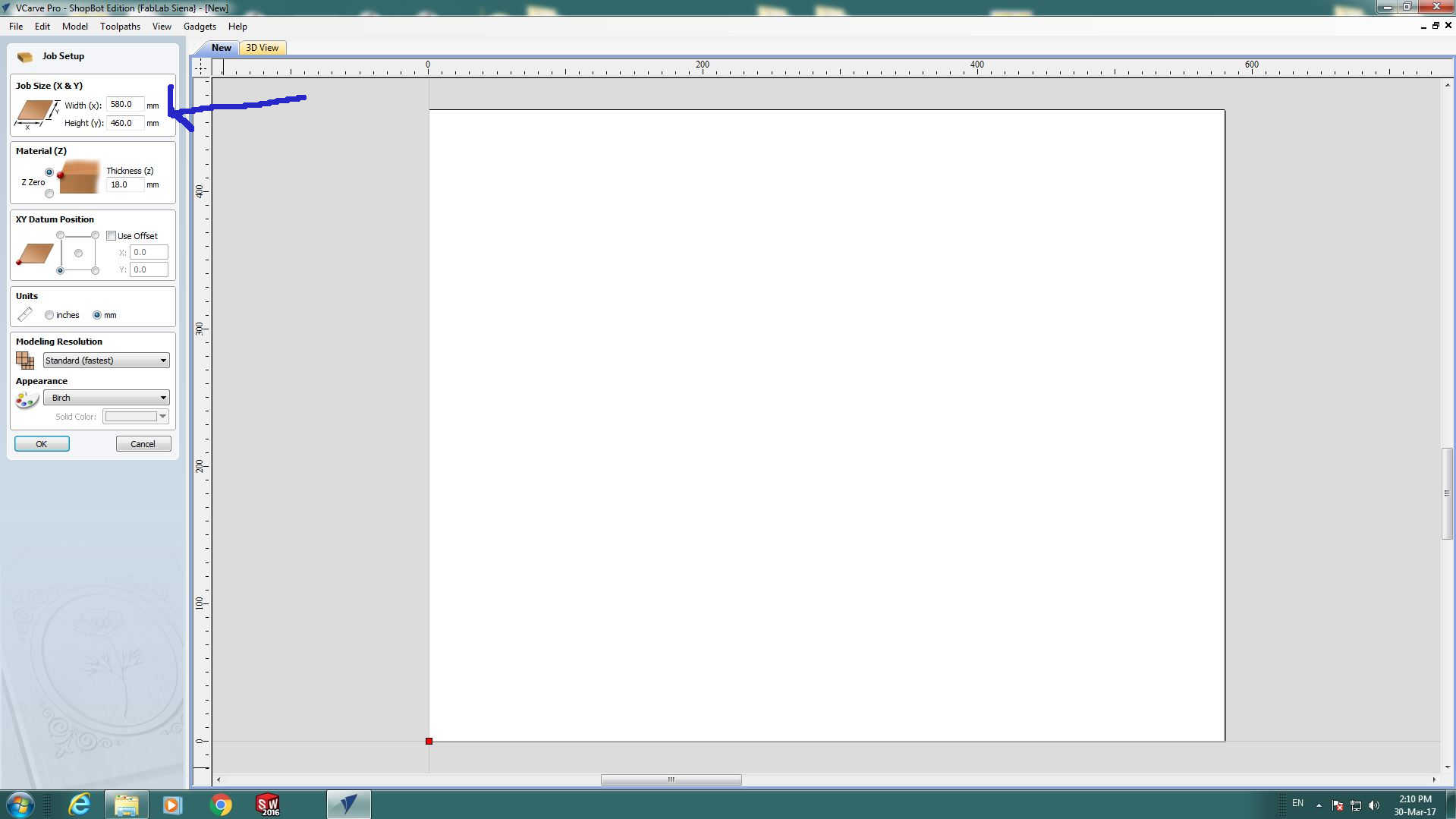 I then positoned my sketch on workspace and set proper settings:
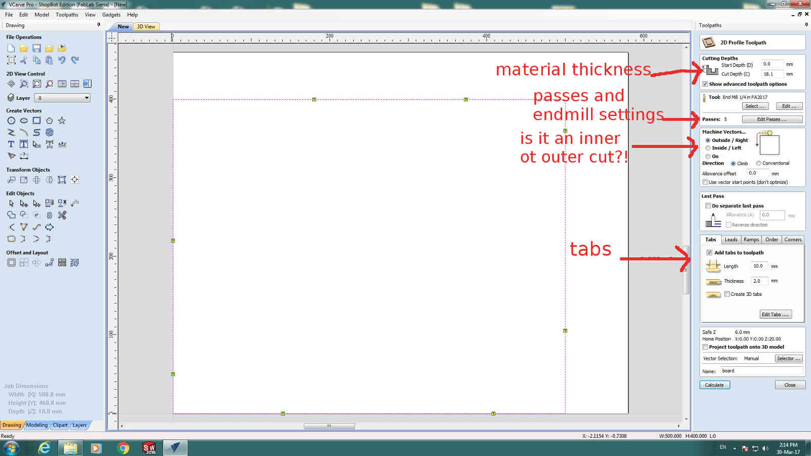 I then calculated path (Calculate button) and saved file (Save toolpath to file icon).
NB: before launching milling file remember to:
- check screws are well fixed
- remove everything from milling board
- test cutting file at safe height (specially if you have so little space like me)
- warmup spindle (Cut-->Spindle Warmup Routine on Sb3)
- set zero with plate and alligator clip
- seized STOP button
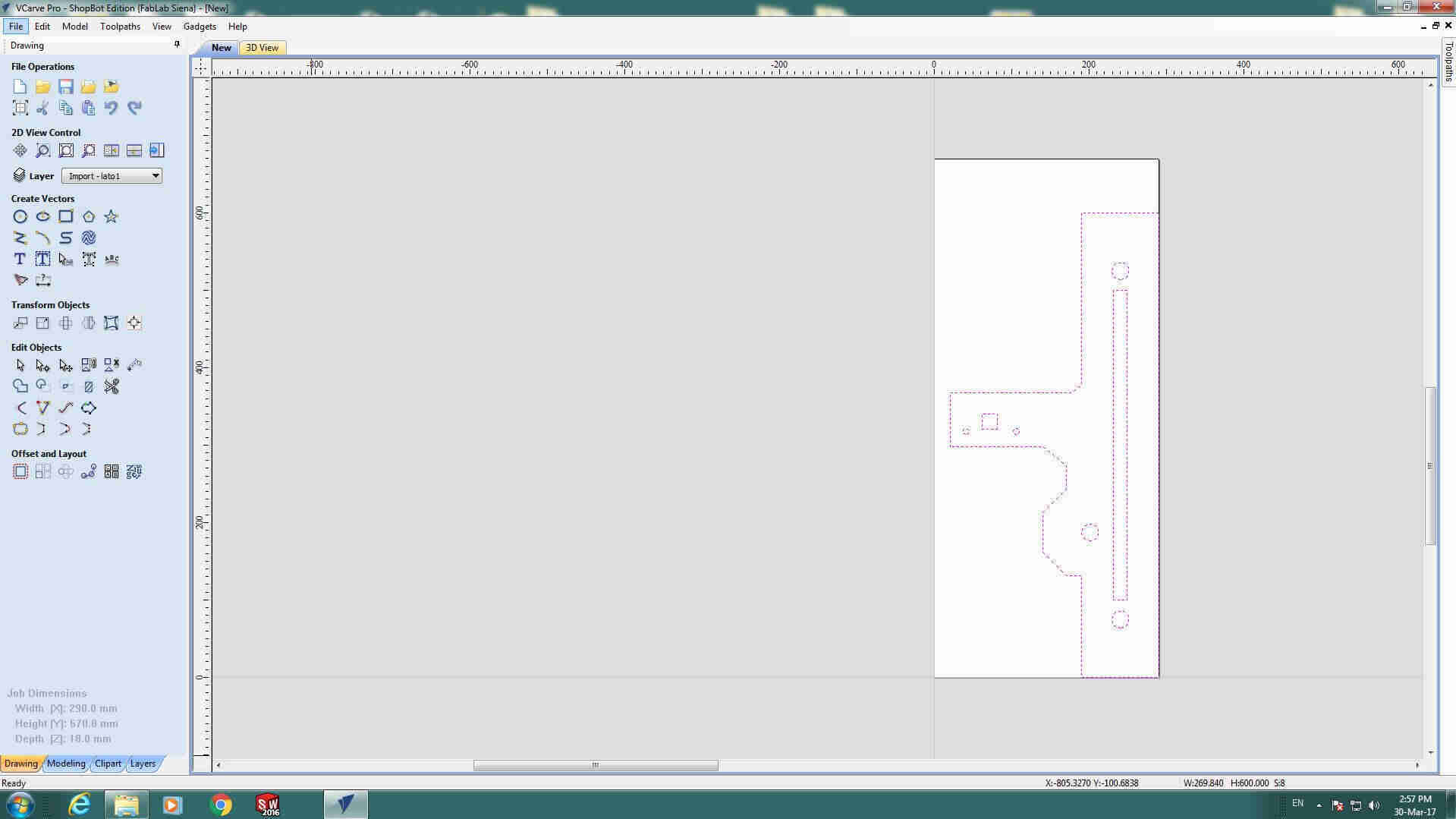
 I repeated those passages also for other parts to be cut:
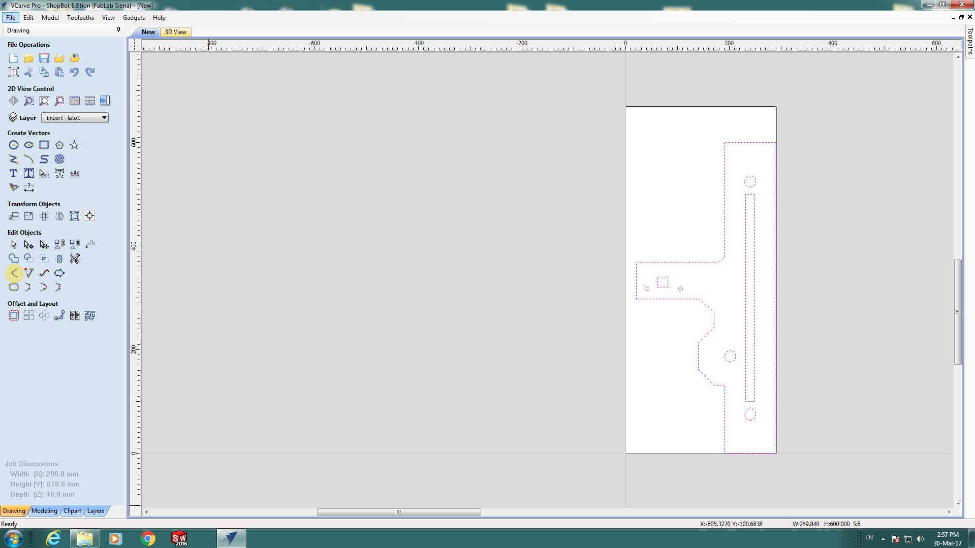
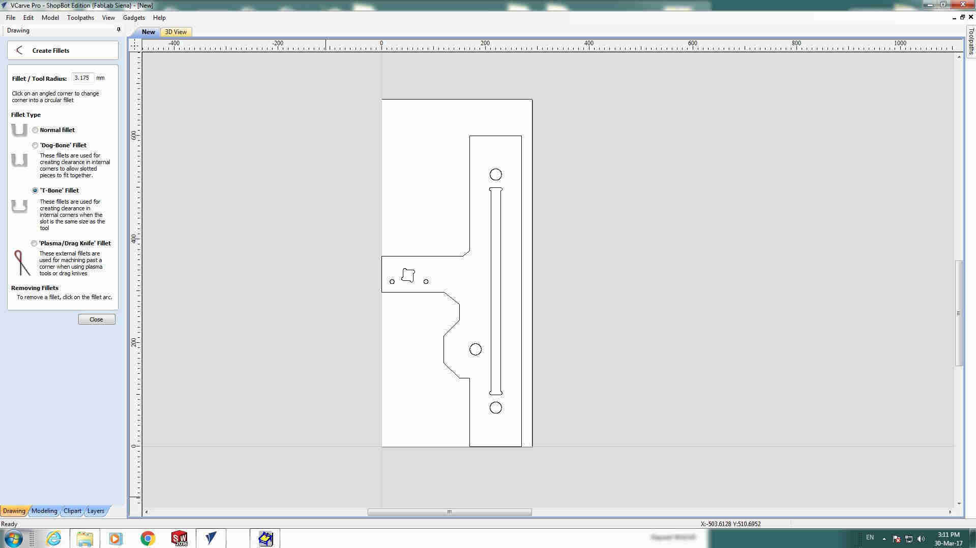
 This time I tried adding dogbones on VCarve directly using Create fillet icon:

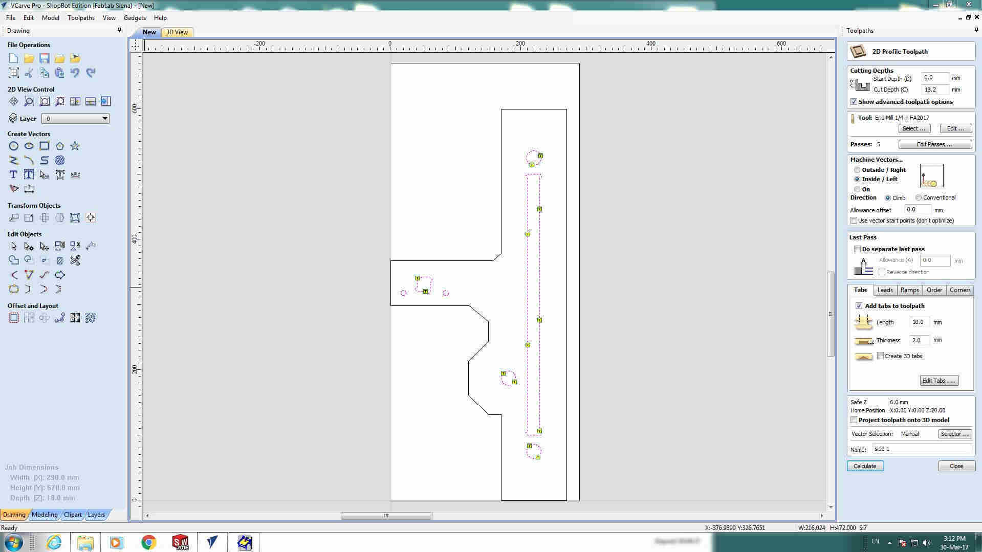
 NB: here I had two cut to be saved separately, one for inner holes and one for outer contour.
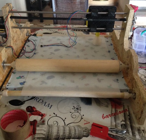
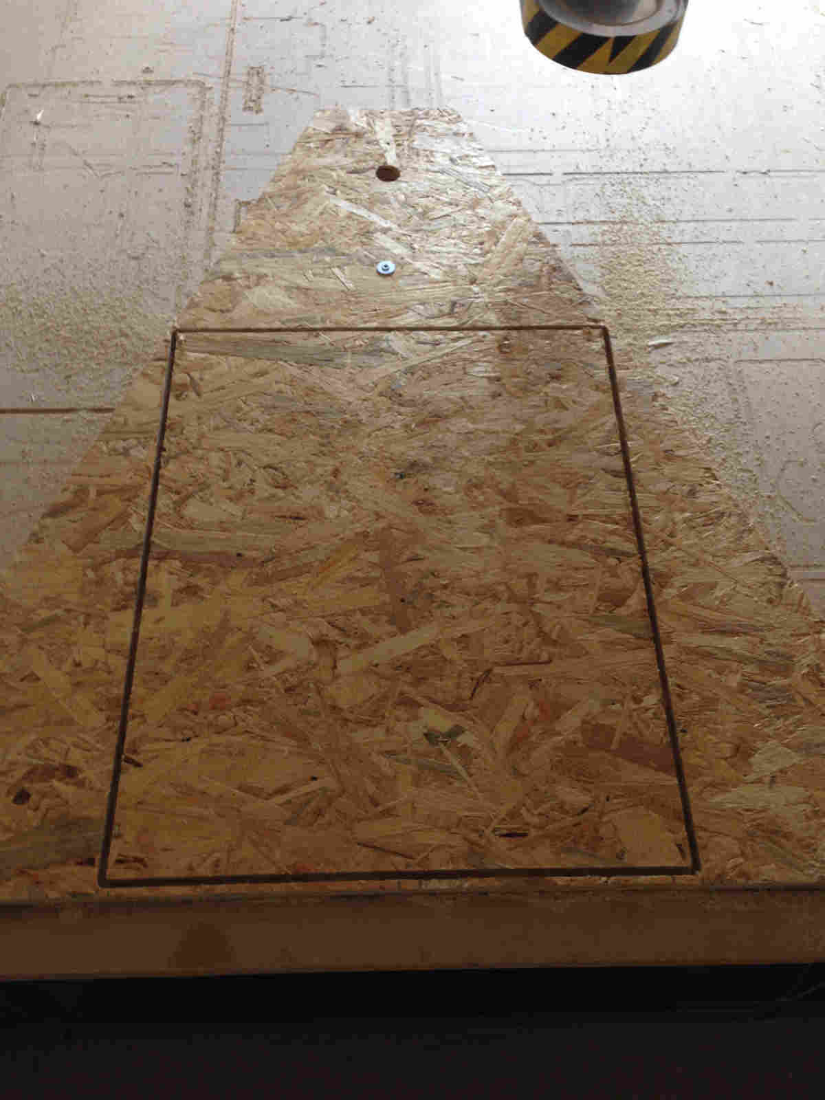
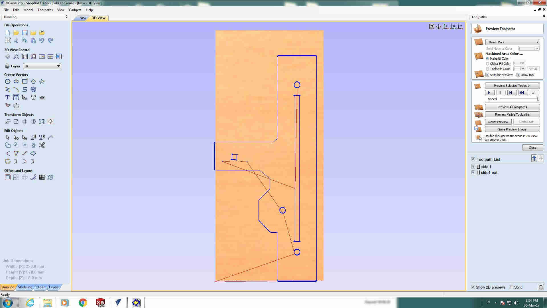
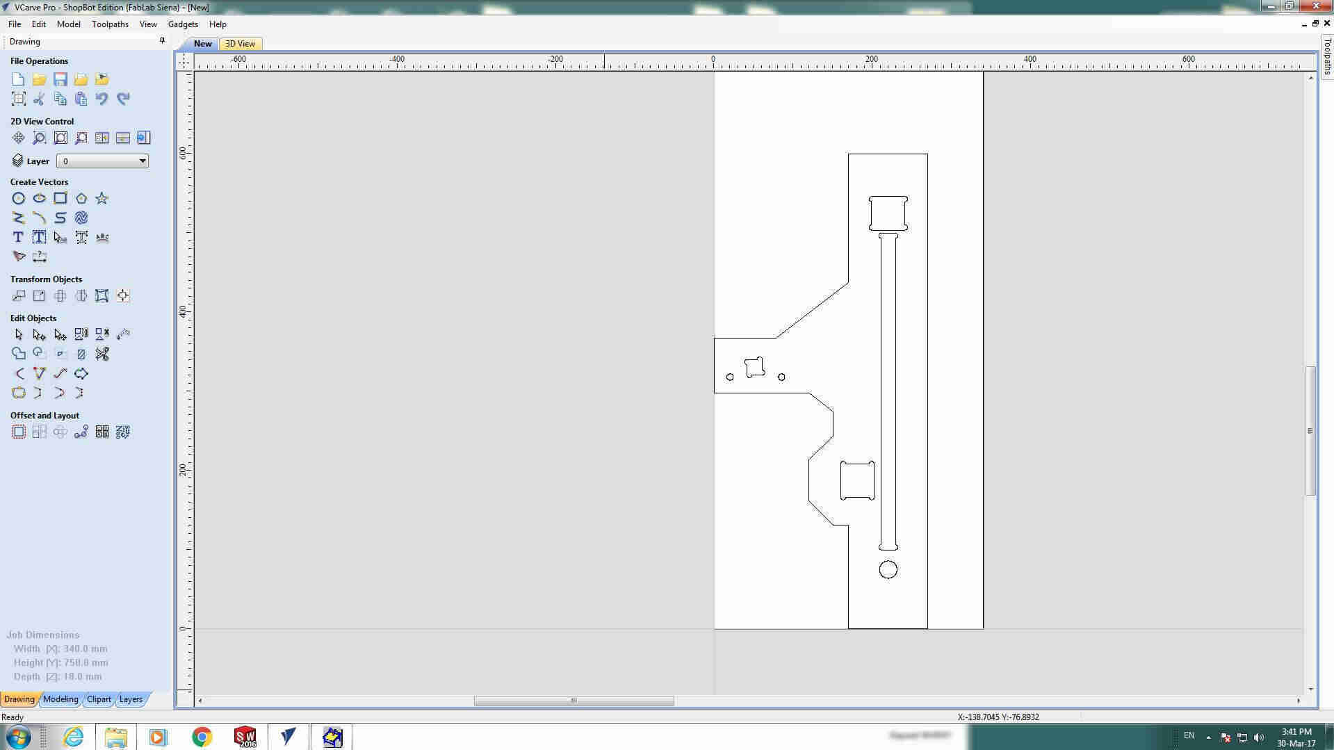
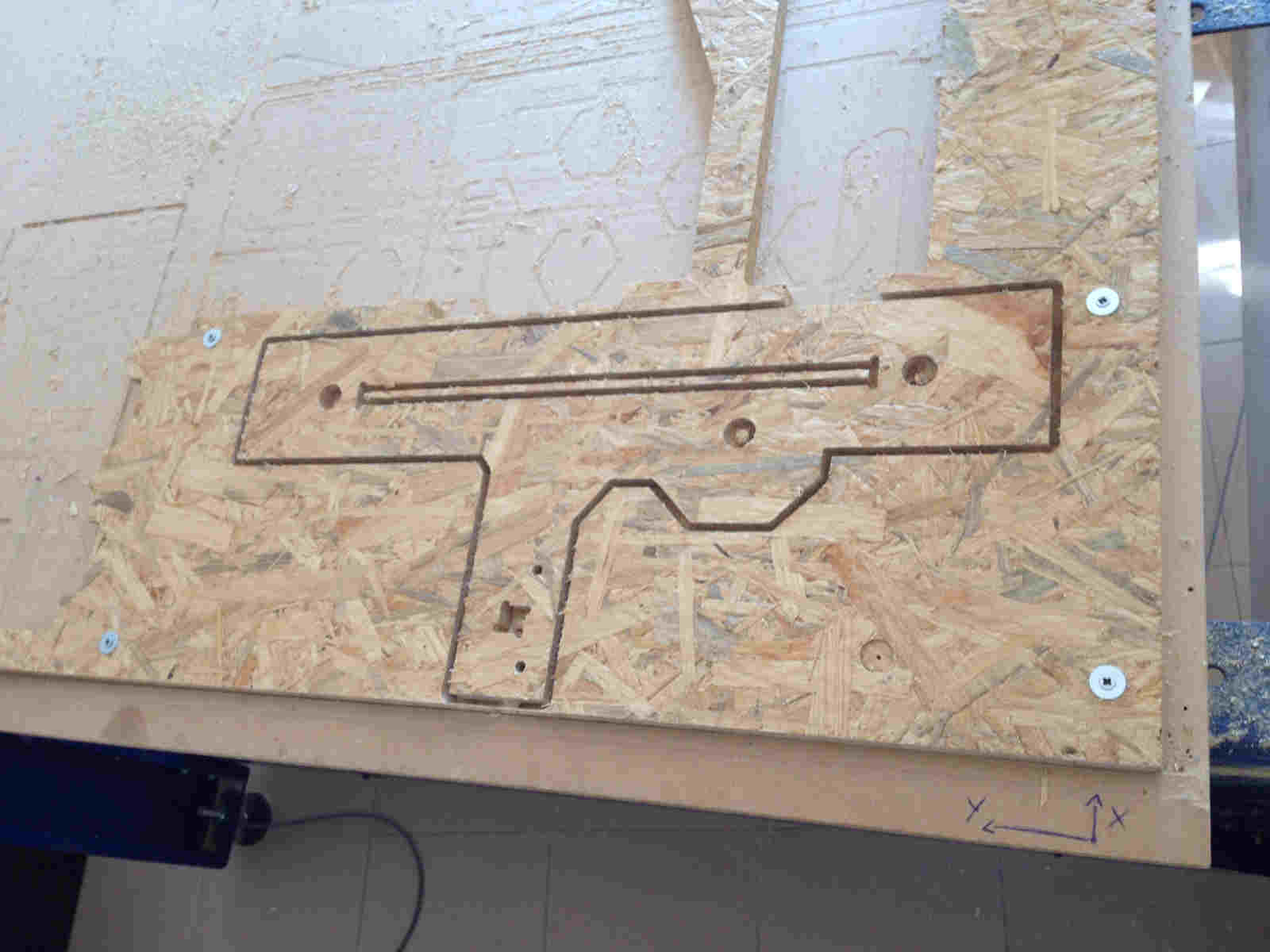 That's how the machine chassis looked like:
Distortion of dimensions in 3D printing & parts fixing
Then I started printing the other parts, both with Ultimaker2 and
Pietro Rustici's Delta.
As for pulleys, as soon as ordered box arrived,
Chiara
and I decided to use commercial ones, at least where it was possible because we were facing
with dimension distortion with 3D printed parts. For instance, depending on filament I used, roller adapters looked too small
or too big for
spheric bearings, or chart had too tiny holes for metallic bars:
The compromise ended up in choosing best printing resolution filament and then fixing dimensions
on Solidworks according
to relative tests. Since I had an exams during those days, I worked from home and Chiara did tests for me: she
suggested to increase some dimensions of 0.3-0.4 mm and decreasing others of same quantity so as to have perfect joint:
Chart
As for chart, I realized that in addition to hole dimensions increasing, I had to consider linear bearings:
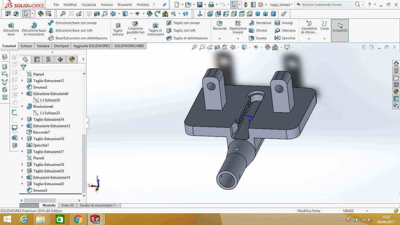
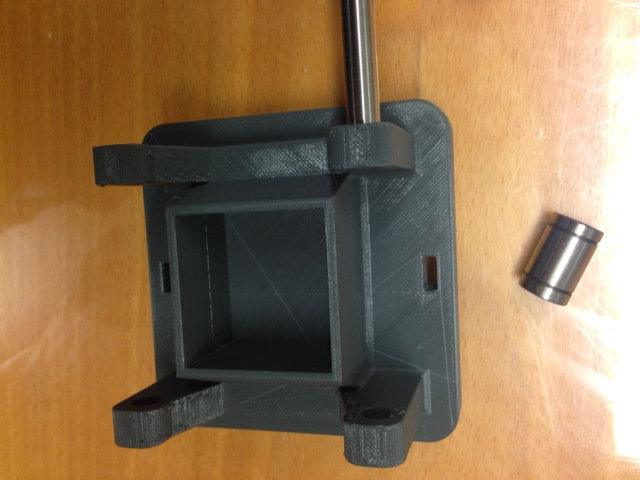 I therefore opened Solidworks and edited the model:
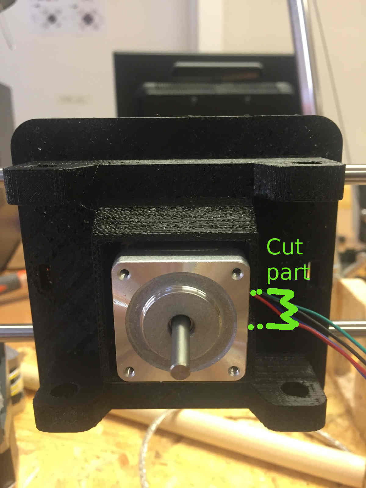
 And also I added an hole for motor wires:
 ...without anyway considering that it was quite useless deisgned like this, because motor couldn't enter the space, but Chiara found a solution:
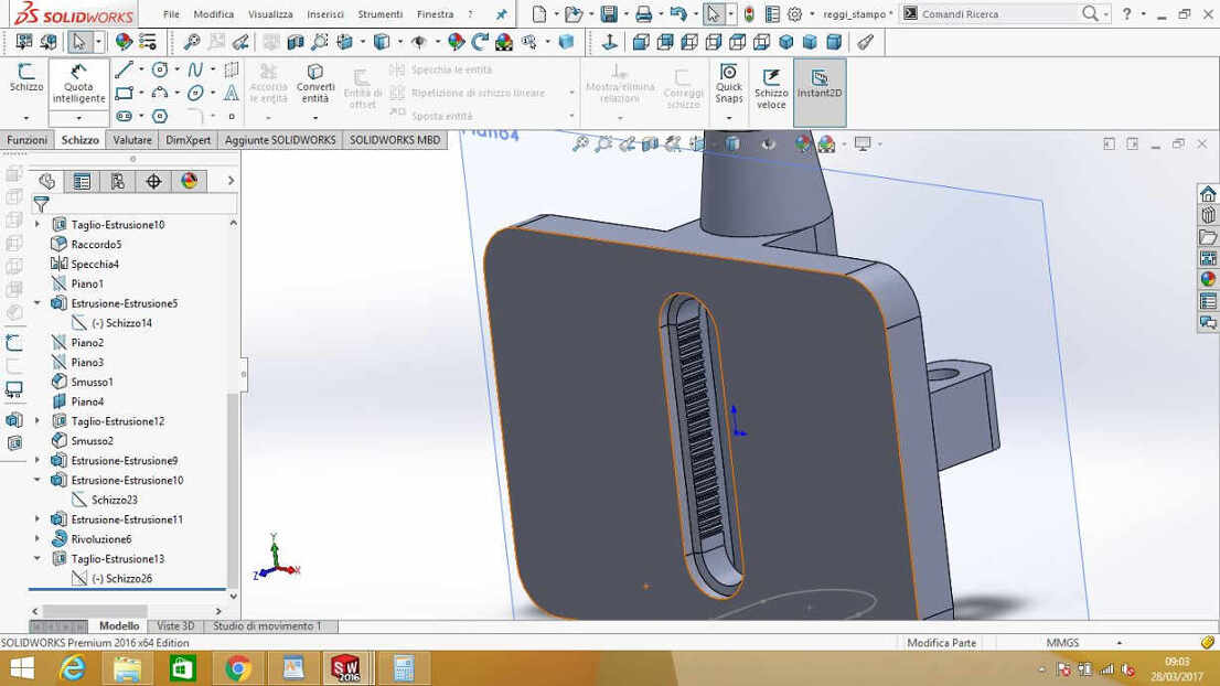
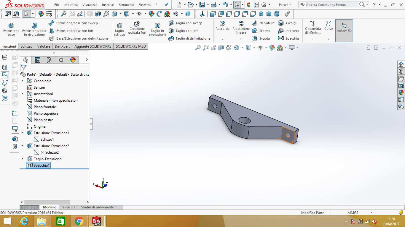
Mold holder
Another part that lacked conderation about mounting process in my design was mold-holder: in addition to previous edits,
I decided to leave a side open to make the pulley enter its place (anyway in the end we decided to use THingiverse pulley and basically
I needn't this change):
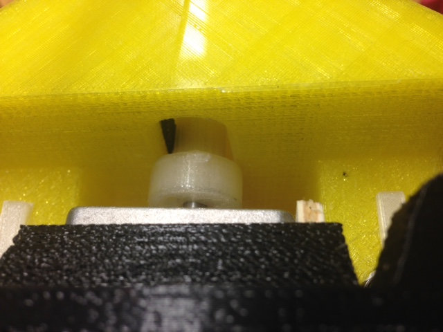
 Actually, printed toothing showed up so bad that we decided to use sandpaper to level it off and to glue GT-2 belt piece on it:
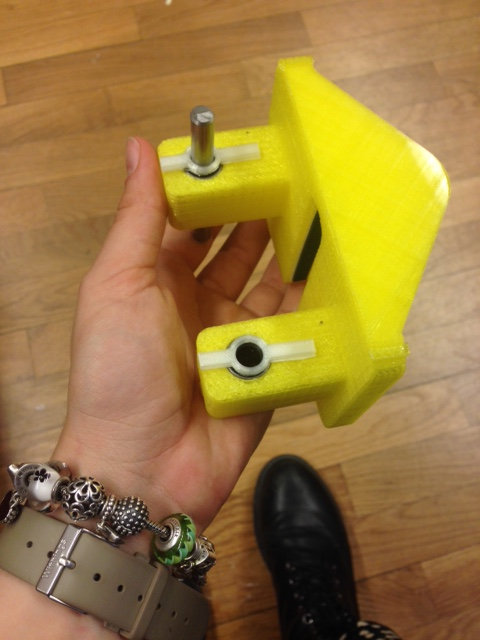 In the picture you can also see two bearing-bloking parts I designed to prevent linear bearings to come out (actually I shoul have decreased
diameter dimension more that 0.4mm).
In the picture you can also see two bearing-bloking parts I designed to prevent linear bearings to come out (actually I shoul have decreased
diameter dimension more that 0.4mm).
Here's how it looked with the mold:
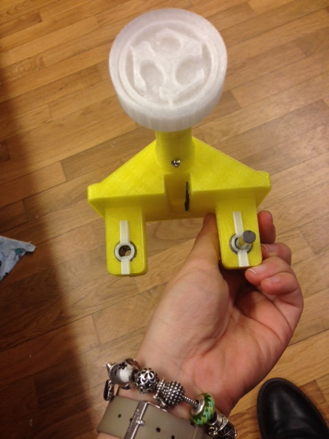 and with the pulley:
 The piece of wood you see is used to fasten the littler NEMA 17 we decided to use.
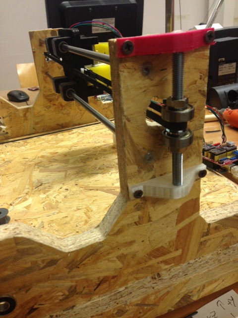
Spheric bearing as belt-sliding assistant & belt
First designed I made showed a pulley screwed (via some supports) to wooden side of the machine, which was needed to help belt
motion fluently. Anyway my instructor suggested me to use threaded bar and spheric bearing so as to have the possibility to fix the
bearing at right height only after mounting it into the bar. I liked his idea and I designer a bar holder on Solidworks:
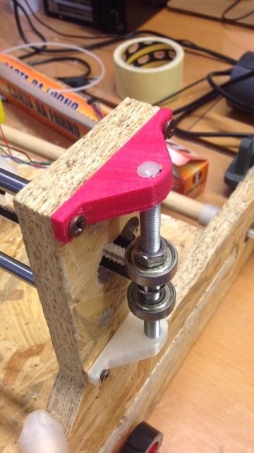
 I mounted it and I realised that using two nuts and a bearing let freedom
to screwing up and down the bar as the chart moved left-right.
I mounted it and I realised that using two nuts and a bearing let freedom
to screwing up and down the bar as the chart moved left-right.
I so found a solution using two bearings and a metallic ring
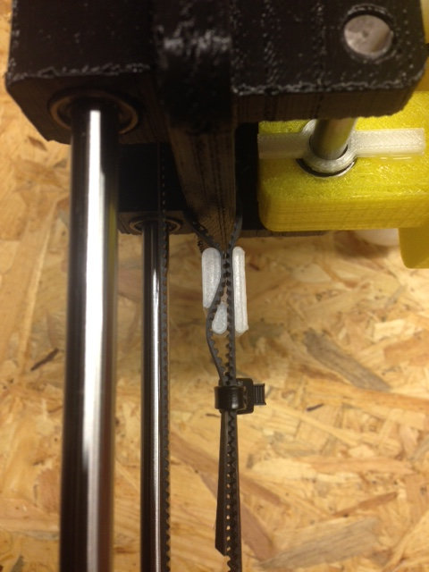
 as for belt ends, I found this clamp on Thingiverse
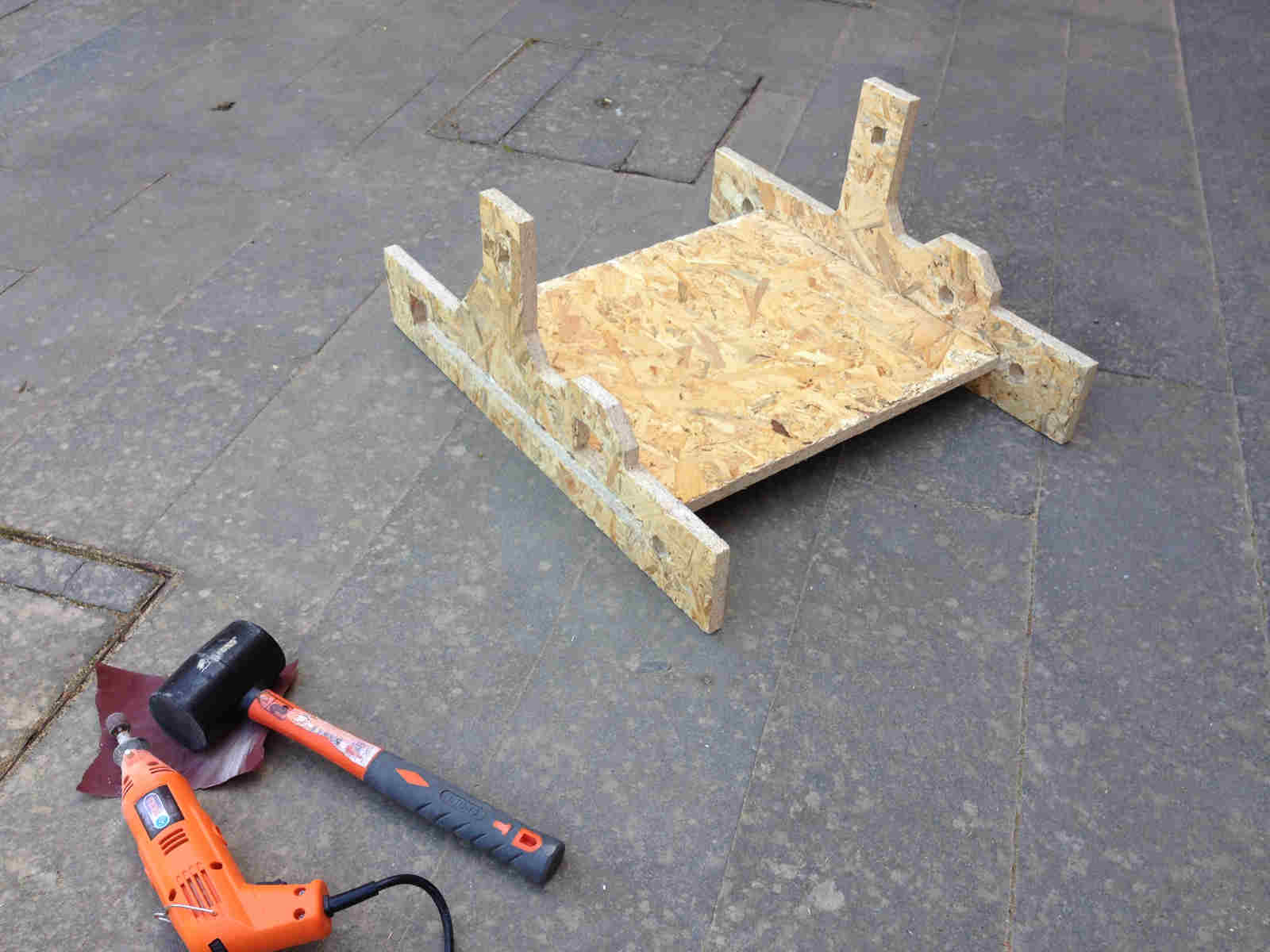
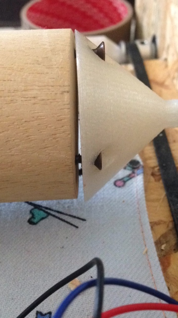
Rollers
Rollers as I said, came out of wood pile of 18 mm diameter that I cut and mounted with adapters:
 I printed many times adapters both because there were three different designed of them (a long one, a short one and one for motors)
and also because
in mounting, I broke many them (I made the huge error to put together both sides of chassis since the beginning and jointing resulted quite delicate).
I printed many times adapters both because there were three different designed of them (a long one, a short one and one for motors)
and also because
in mounting, I broke many them (I made the huge error to put together both sides of chassis since the beginning and jointing resulted quite delicate).
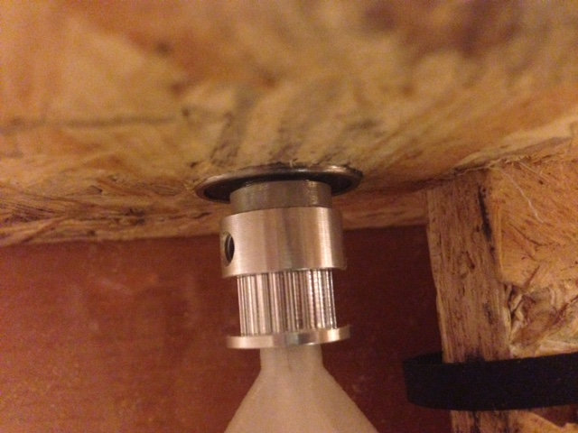
As soon as I mounted the rollers, owing
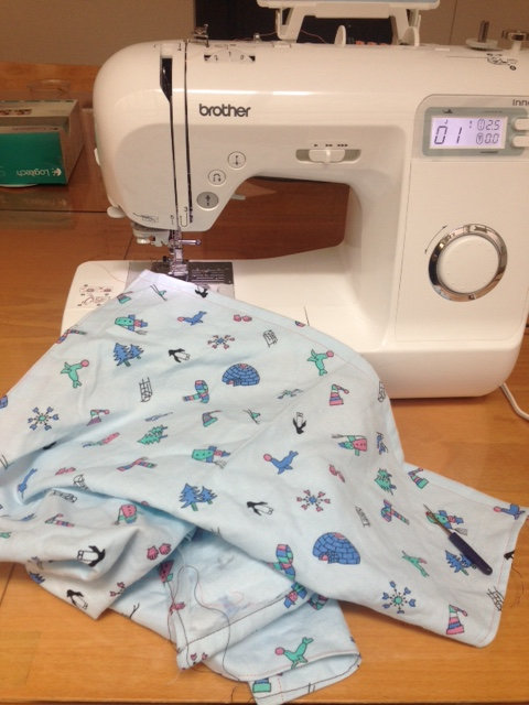
to the fact that just one of them was provided with a motor, I wanted to help movement transmission with GT-2 belt (even i conveyor bf just the conveyor belt
could be enough). Together with Chiara, we measured precisely were to cut the belt and I then sewed and glued it.
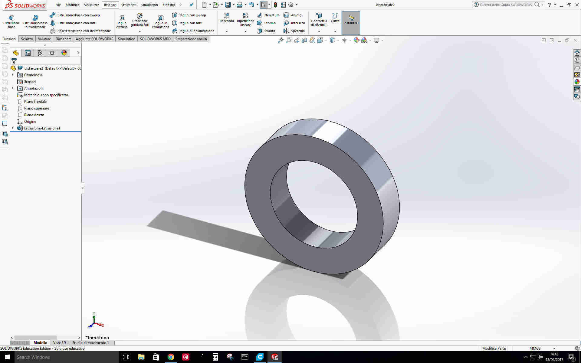
Now, I saw that no-motor roller had space enough to slide a bit sideways whereas I wanted it to be aligned with the other roller. I so designed two
spacers:
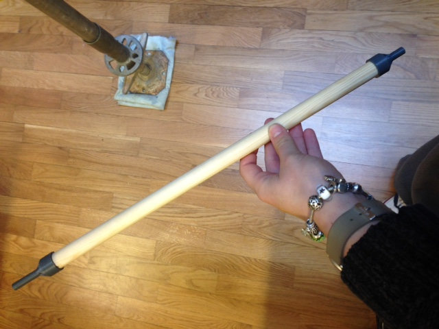
Rolling pin
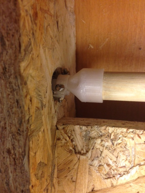
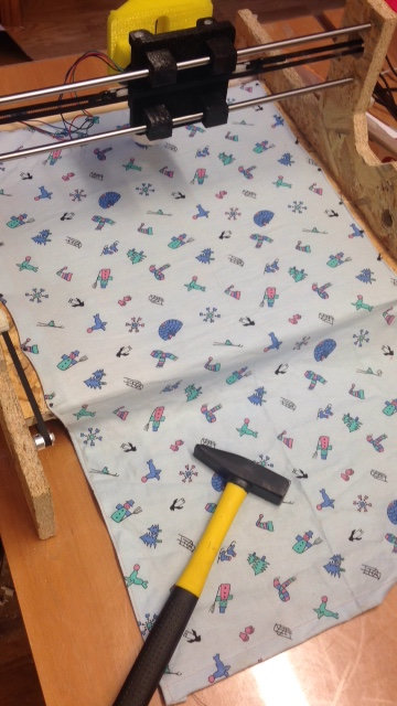
After covering the wooden board with some fabric...
 I wanted to mount the rolling pin. Many thanks to Simone Guercio that helped me a lot with 50mm wood pile cutting.
My going heavy with sandpaper revealed to be not enough and round faces weren't perfectly flat, with this result:
 A rolling test didn't give back so bad motion but the idea is to change the adapters with some like the ones on the rollers.
As a final (by now) touch, I added bakery paper to work as conveyor belt.