Introduction
The assignments of this week were:- Group assignment: design a machine (mechanism+automation), including the end effector build the passive parts and operate it manually
- document the group project and your individual contribution
MACHINE DESIGN
This was the first week of machine building. We are six students so our instructor divided us in groups of two. I worked with Silvia Palazzi. To check our work, follow this link to read our documentation.
PERSONAL CONTRIBUTION
Honestly this week I haven't contributed to much because I had to do my last university exam. I have designed only a piece: cookie cutter. I used Illustrator and Fusion 360 to doing it.
We decided to engrave our cookie with the Fab Lab logo. I have downloaded it from Internet and then I imported it on Illustrator.
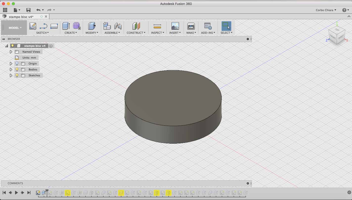
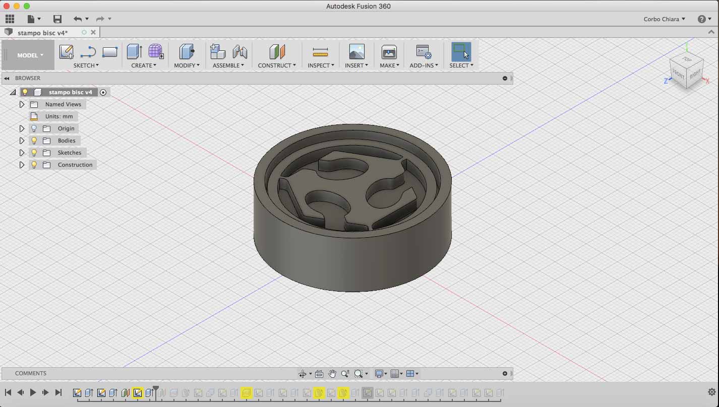
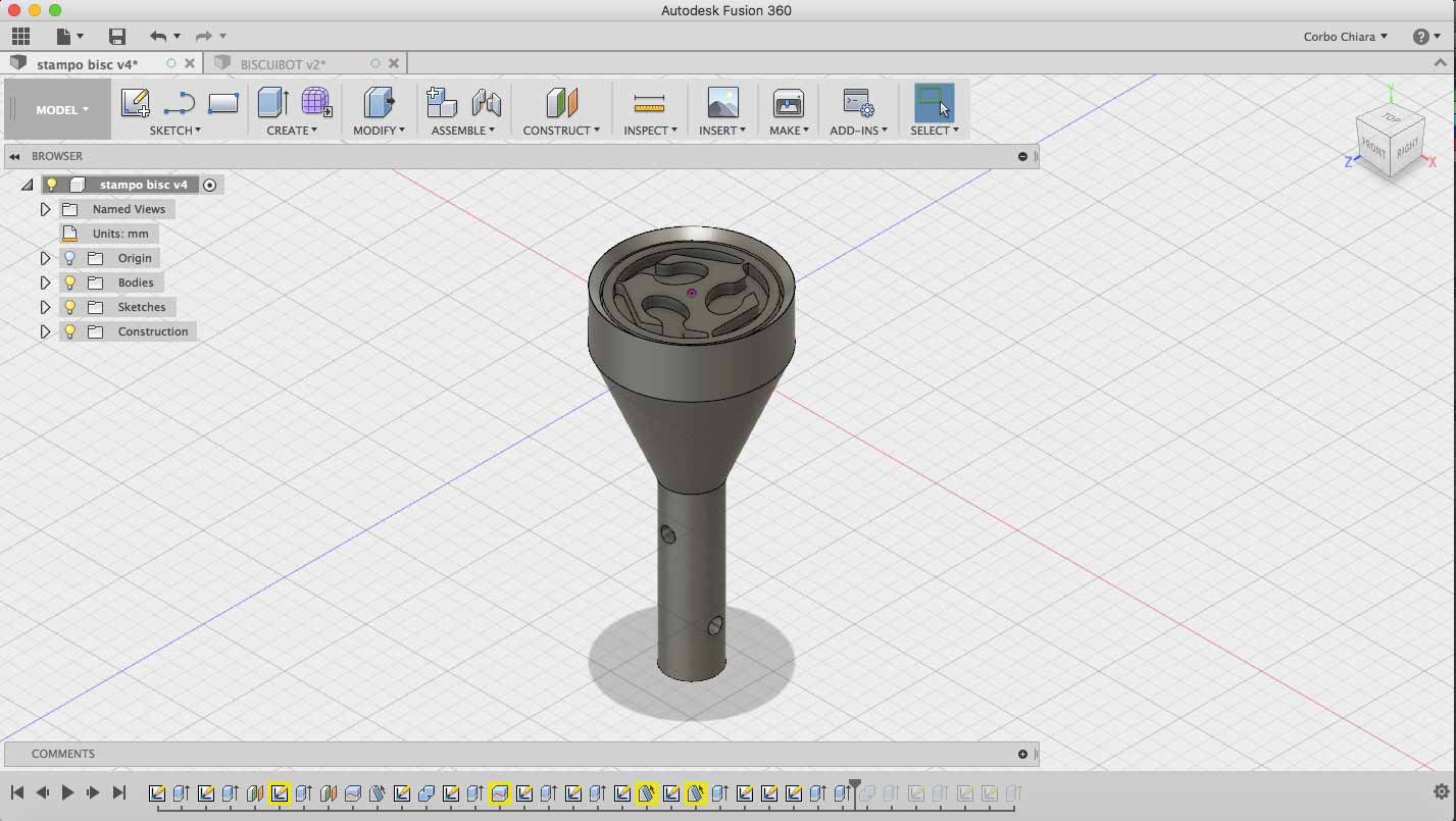
I turned the picture like a vectorial image and then I exported it in .dxf. Why .dxf file? Because Fusion360 can open this kind of files. I opened Fusion360 and I created a new file. I drew a circle and then I extruded it.
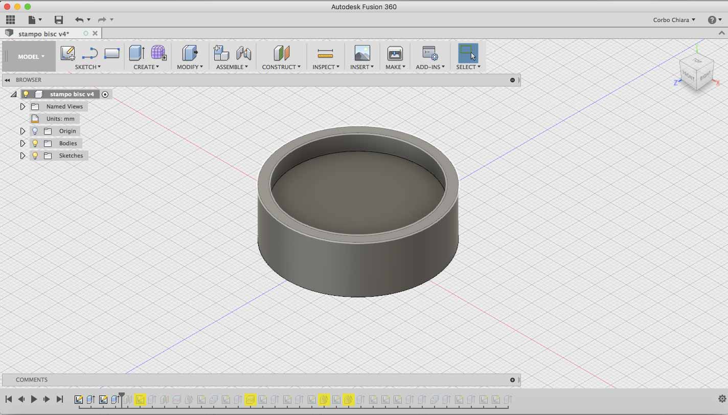
Then I have created a margin on shape. It will be the cookie cutter. Is hight 5mm.
Now It's time to import the picture. First of all I created an offset plane on the cilinder because I want to put the pic on it. I have used this command.
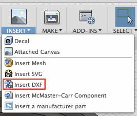
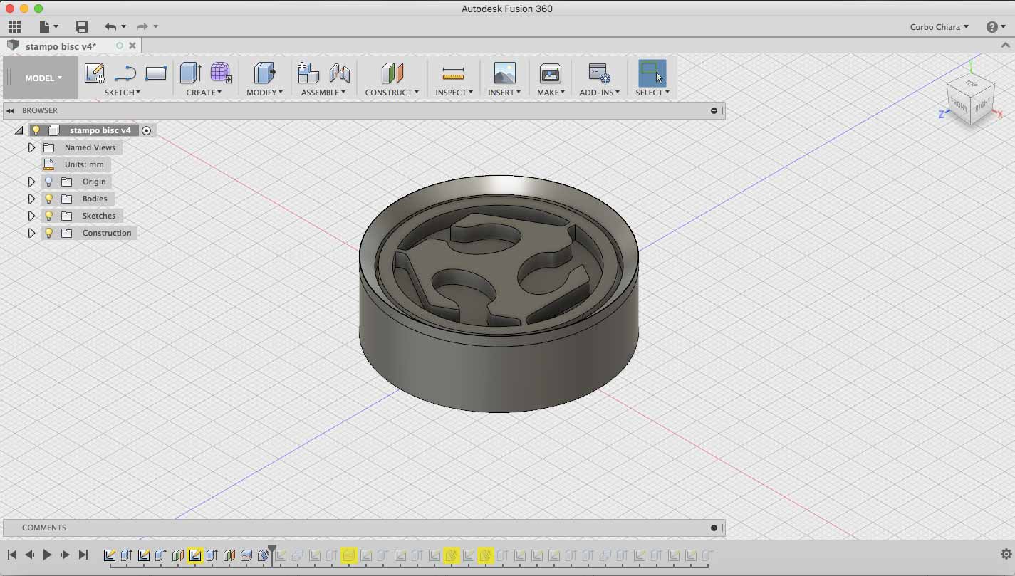
The picture was to big so I have adapted it to the cylinder. I moved it in the right position and then I have extruded it for 3mm.
Cookie cutter is almost ready. To get a better cut, I used draft command to flatten last 2mm of the outline.
Now it's time to build support for our BISCUIBOT. This is the part who Silvia have drew.
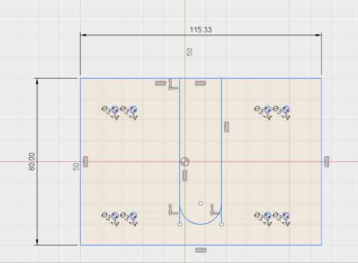
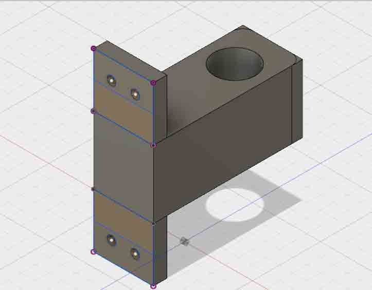
Under cookiecutter I added a new offset plane, then I drew a new cilinder on it. I used draft command to flatten the surface leaving at the top a plane of 1.5cm of diameter.
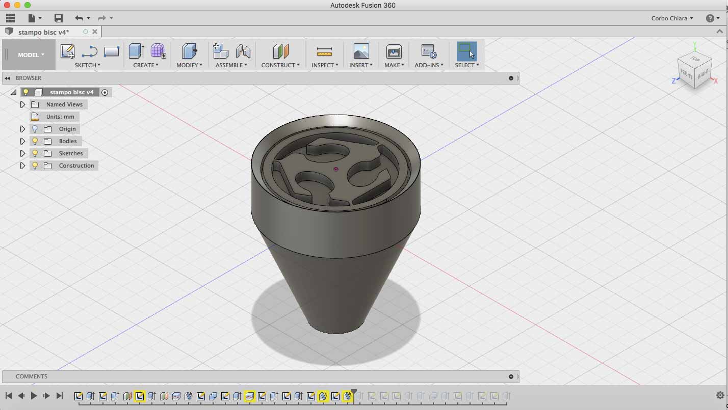
Our support have a diameter of 1.5cm and an heights of 4.7cm (distance from machine plane to support), so I draw the last cylinder with the same dimension. On it I drew two hole for the screws. I will use it to fix it in the support.
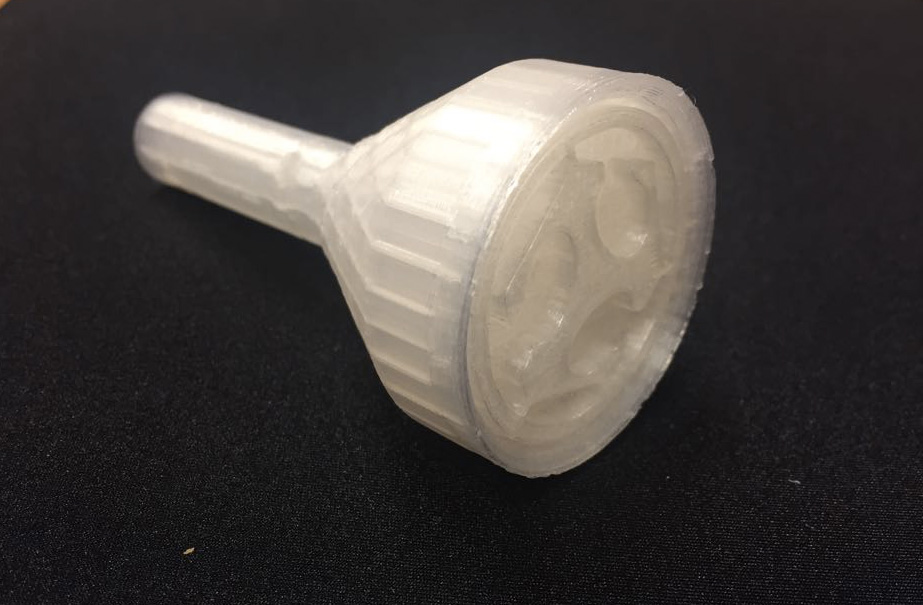
Silvia tried to print it and this is the result.
RENDERING AND ANIMATION
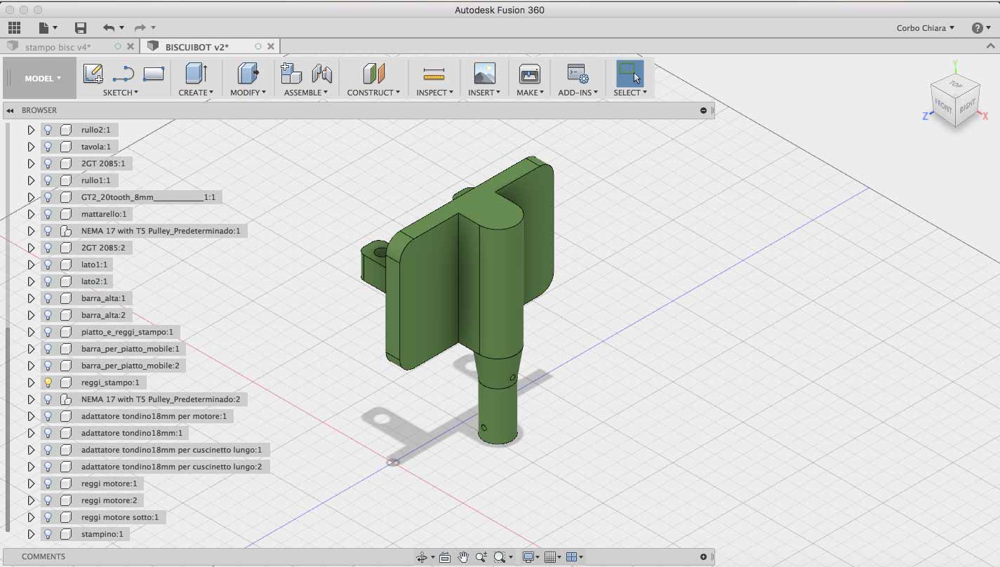
Silvia assembled BISCUIBOT on his computer using Solidworks. I have a Mac, so I couldn't use this software and I have use Fusion360. So, to make rendering she have exported the model like .iges because it was supported by both. With Fusion360 I wanted to try to make an animation of our machine. I never done it before so I looking for some tutorial on Youtube. I have found this one (link). It show me how make an animation of a rotation. I have opened our BISCUIBOT on Fusion and then I move it on Animation menu.
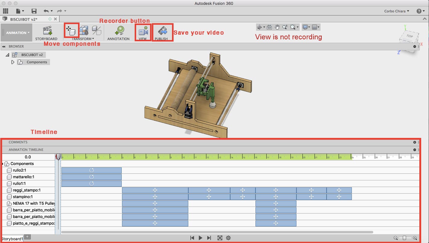
These are the main command that I have used for doing it. First of all I have created the animation for the rolling pin and wood rods which had the same animation. So on the timeline I have selected the duration of animation. In this case I select 5 second of animation.
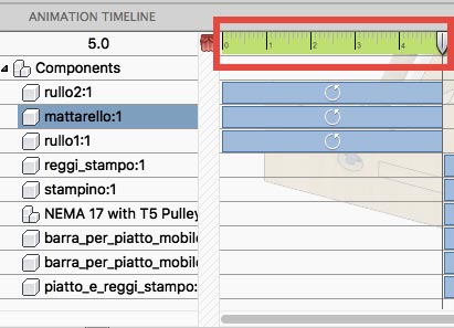
I have selected the first component, and then I pressed on transform components.
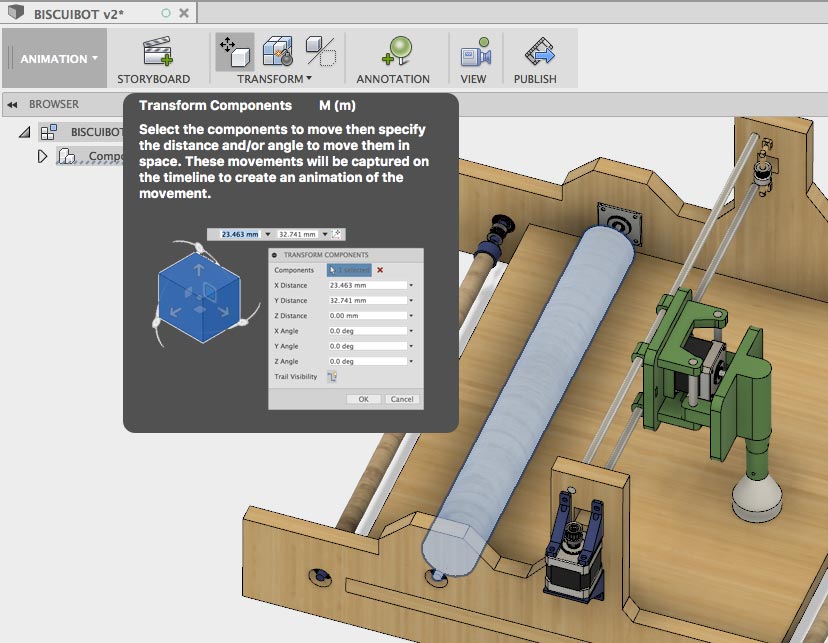
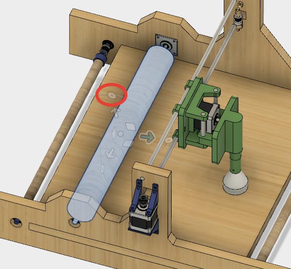
These are the command that I can use. I have show which one I have used for make rotation. I followed the same process for the two wood rods and I have syncronized them. After that I followed the same workflow for the other components. I have selected which were the right ones and then I have simulated the movement. You can see the results on group documentation.
3D PRINT
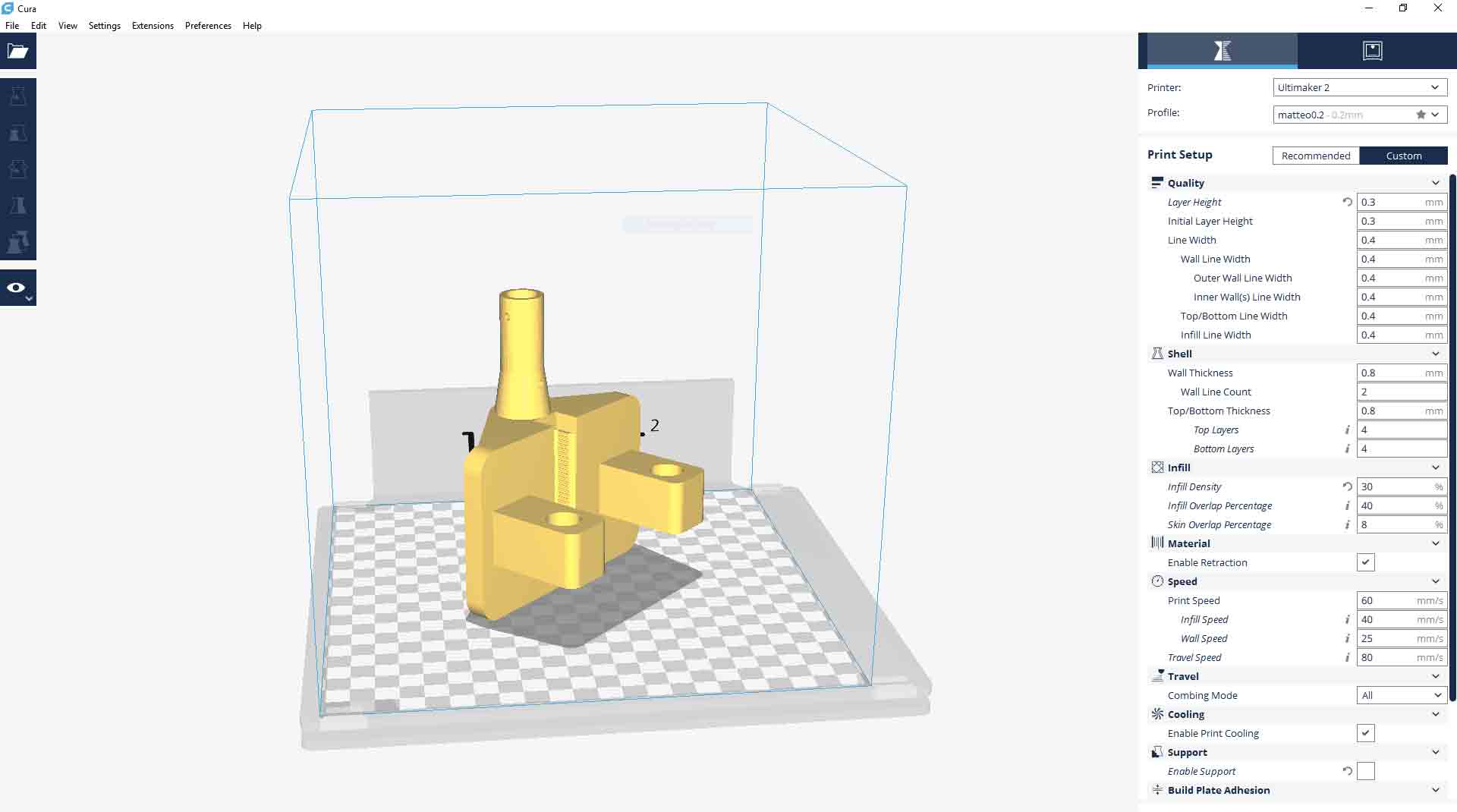
Meanwhile I have printed some parts of our machine with our 3D printer. First of all I have printed chart. This print was very long (almost 15 hours) and at the end I got this:
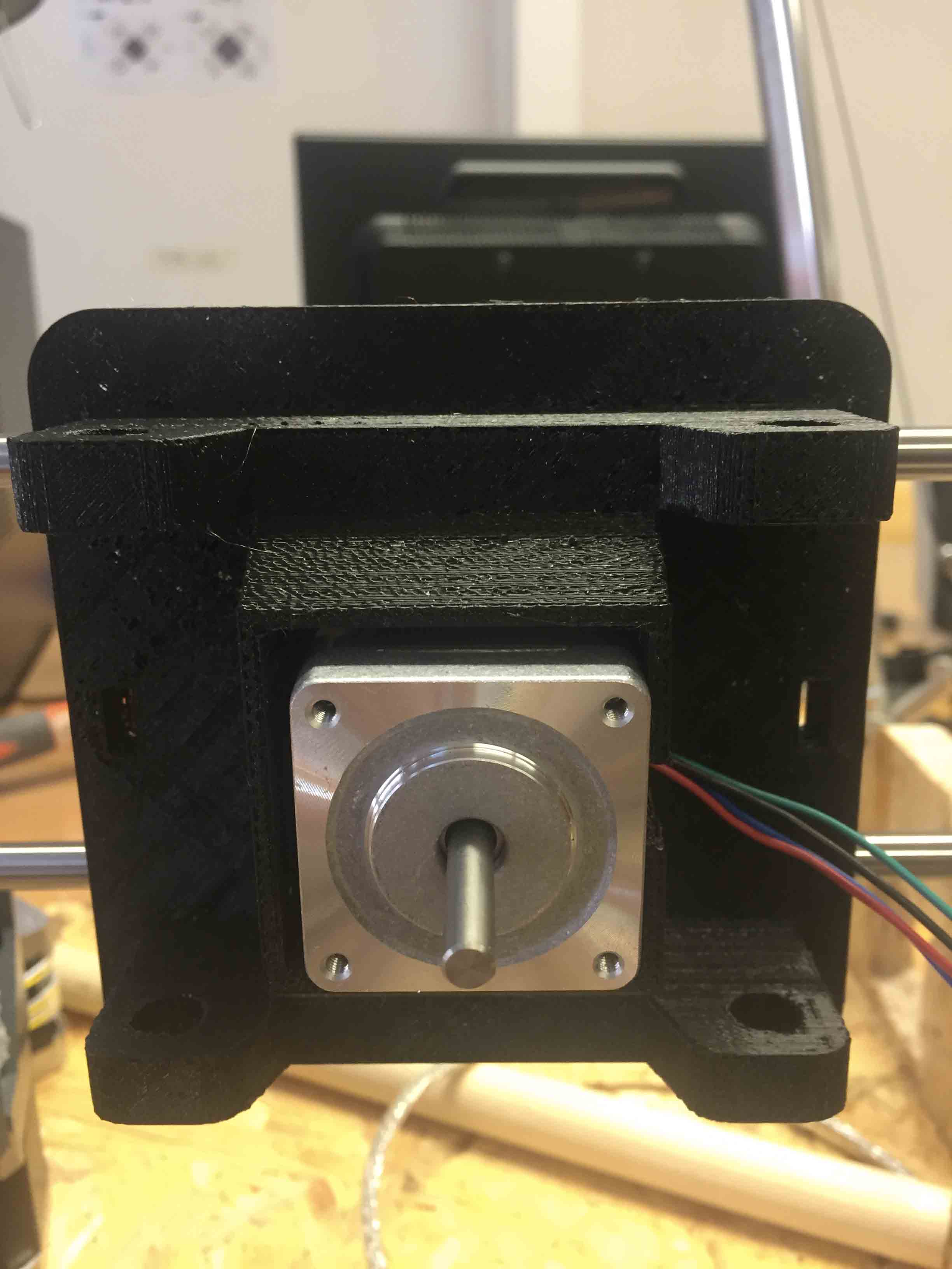
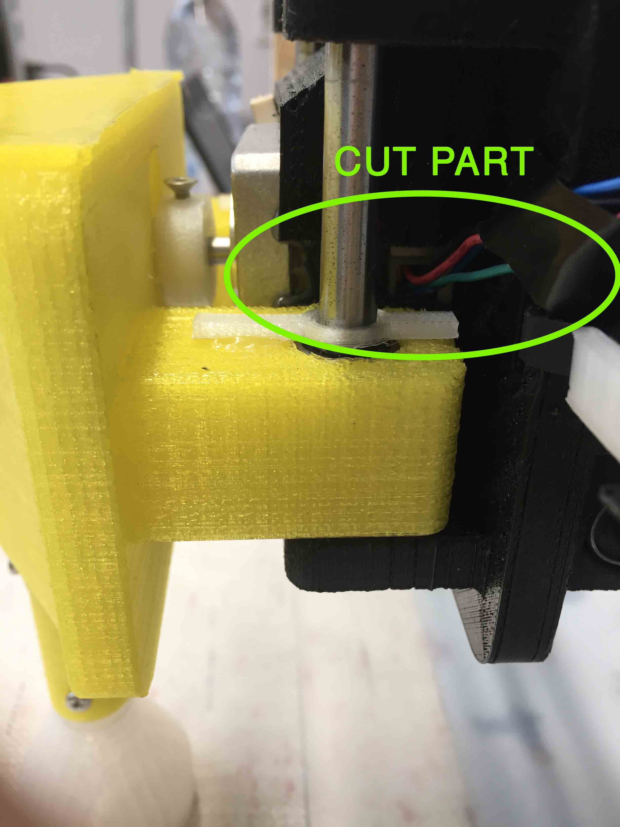
It isn’t the best print that I ever done. Surely I have done some mistakes on Cura, but even material wasn’t the best one. I got another problem: motor didn’t have enough space for the cable, so I have found an “Art Attack” solution. With a box-cutter I have cut a little part on a side. Thanks ugly print!
Then I have printed mold-holder. This print was long as the first one. I have used different settings on Cura to create my .stl.
At the end mold-holder looks perfect but it isn’t.
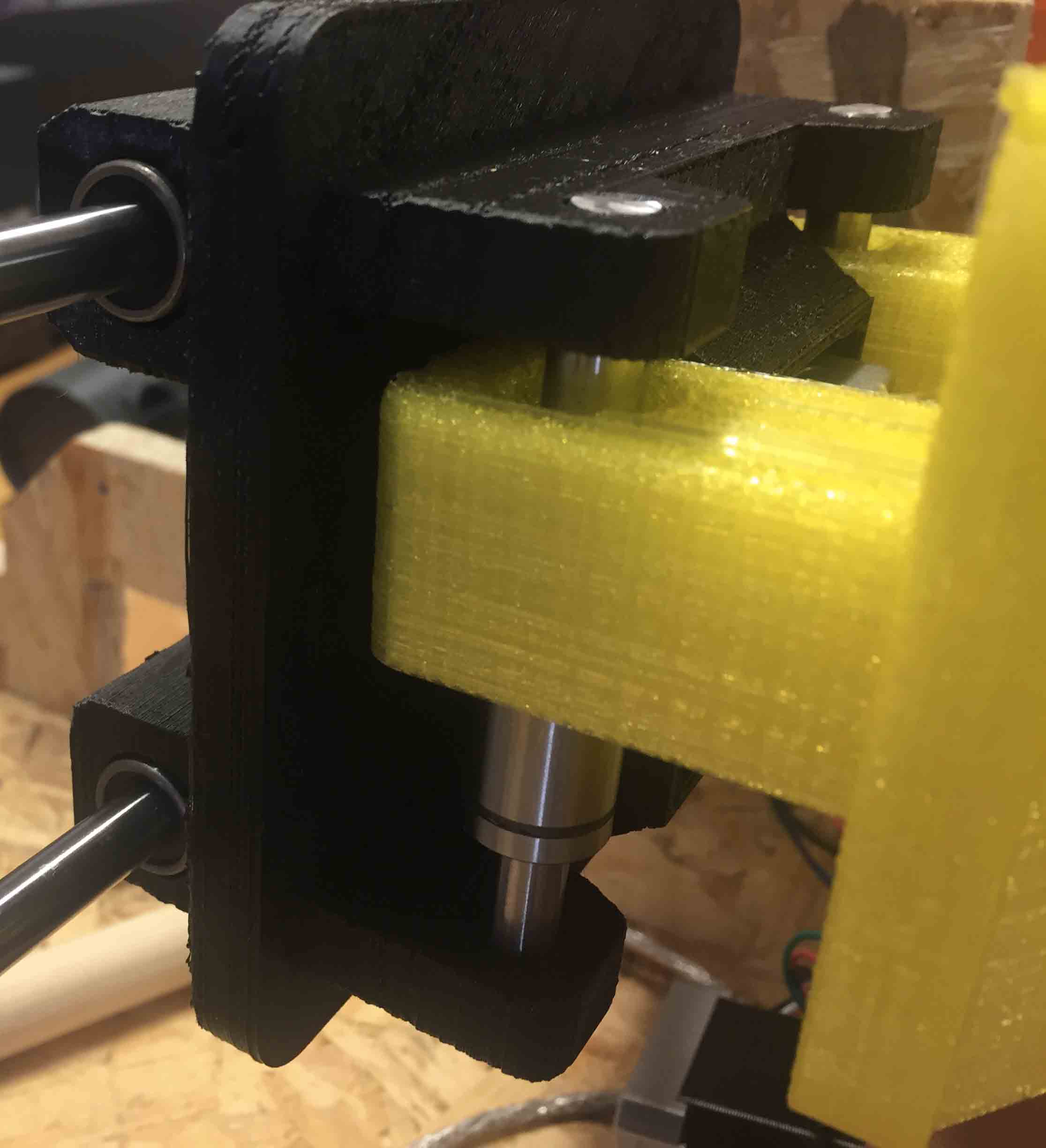
FIRST PROBLEM: linear bearing come out.
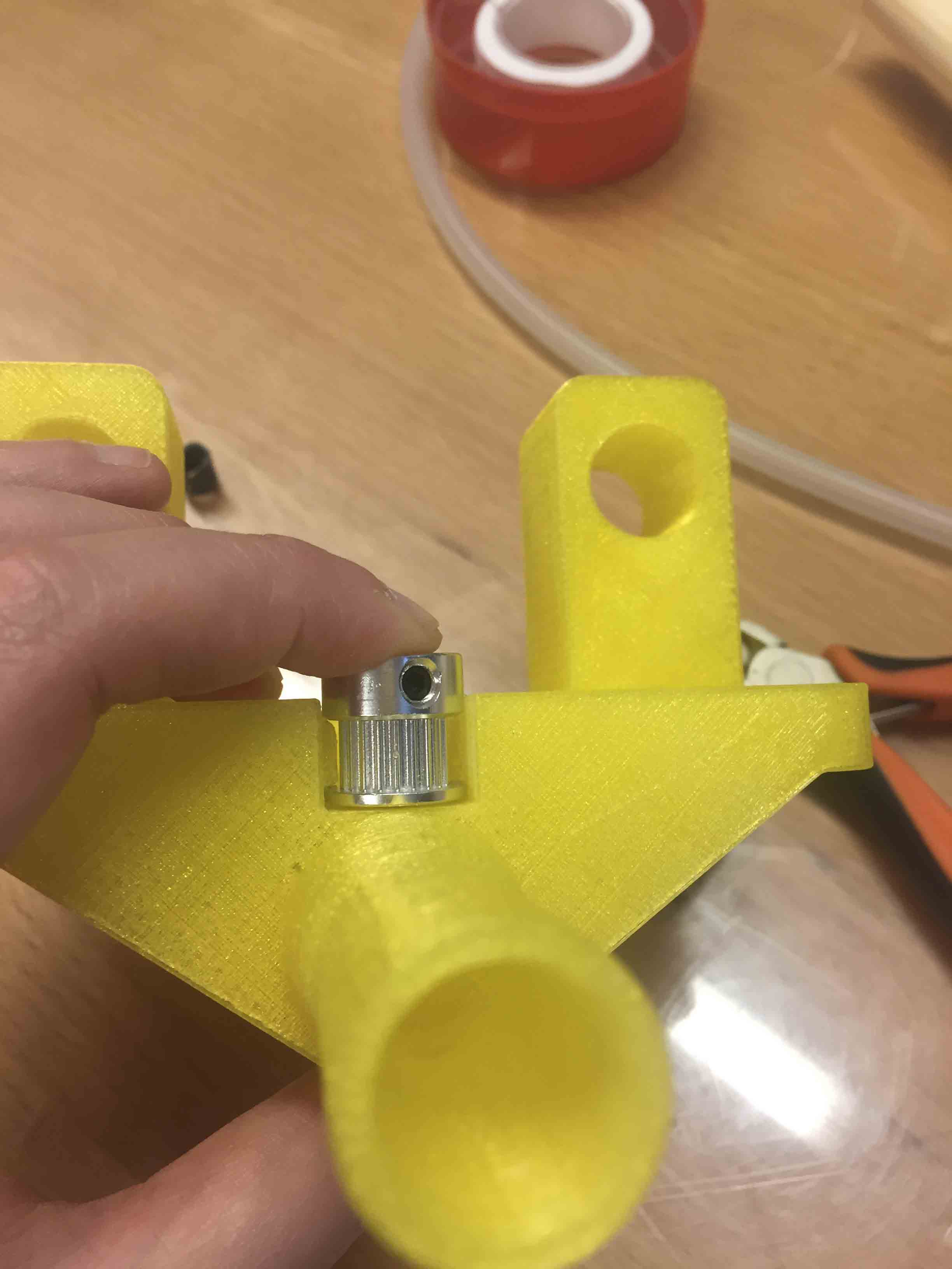
SECOND PROBLEM: pulley didn’t work. It was to big for our design.
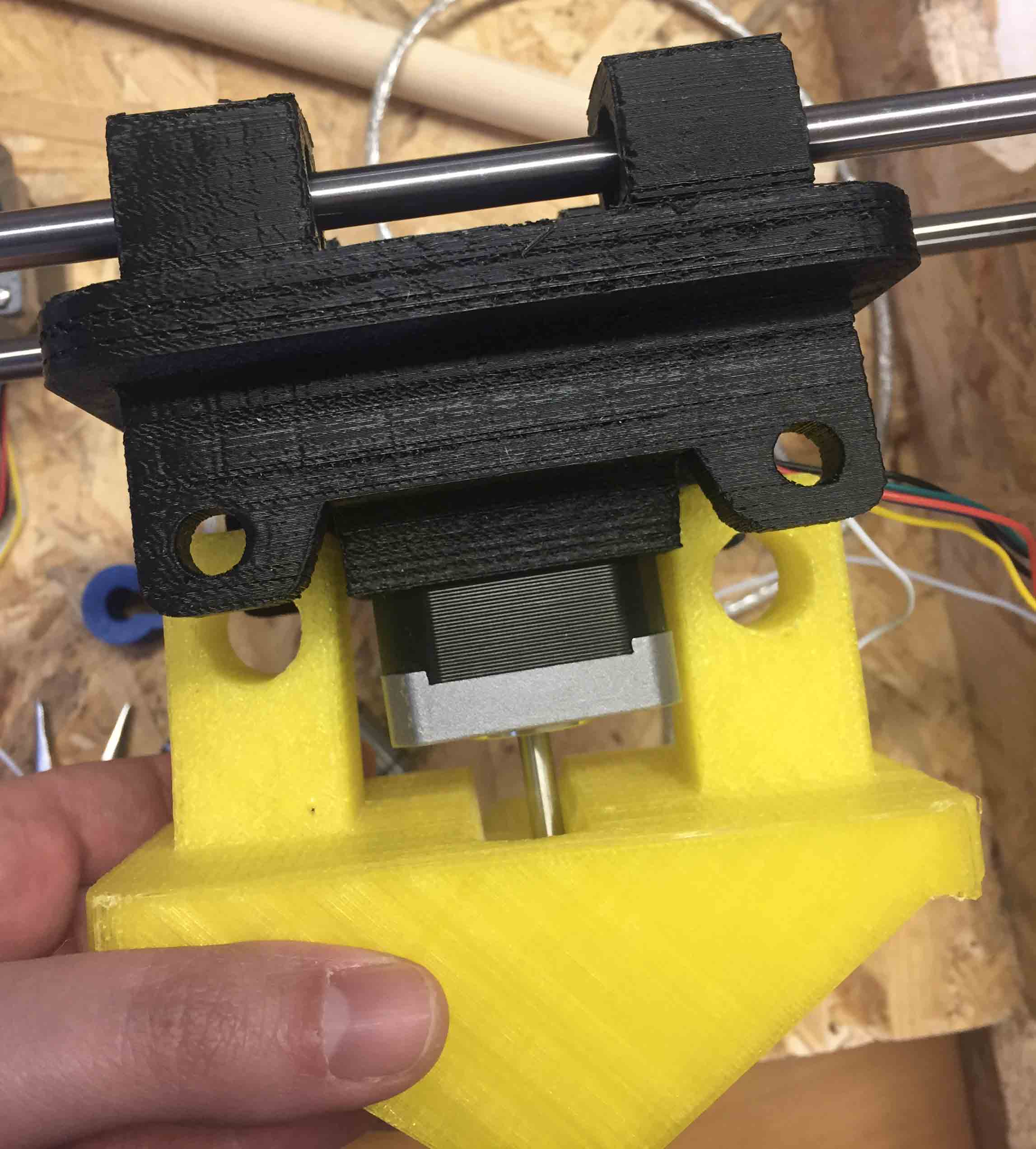
THIRD PROBLEM: Nema 17 was too long for our design.
I became crazy to find a solution. Plan B was redesign mold-holder. To save time I thought to design a modular one:
This part should have been in plexiglass. The plan was cut two parts of it and on a side gluing a piece of GT-2 belt.
I have redesign it longer as Nema 17. Plan was to screw them on plexiglass parts. Like support for our cookies cutter I would have draw a support to screw on plexiglass too.
This solution wasn’t efficient enough, because was very hard redraw all this components without some mistakes. With Silvia thought to modify the original piece. How? For the first and second problem Silvia found an elegant solution. You can see it on her documentation For the third problem we decided to change stepper motor. We used a smaller Nema 17.

This work is licensed under aCreative Commons Attribution - ShareAlike 4.0 International License.