Introduction
Since this week assignment has a lot of time concern, I will report my work as a diary, so as to best show
how I organized my work to go through the process of machining and building.
NOTE: seriously believe me when I say time concern:
it took me from 11 AM to 7:45 PM (with an hour break) just from Vcarve file preparation to removing cut parts from workspace.
Below I list this week most important behaviours:
- quick design
- prototyping with laser cutter
- FIXING
- before machining: check, double-ckeck, triple check, quadruple-check
- careful and focus while machining
- PATIENCE and NO RUSH
- focus -not just like the other weeks, you'll better understand when monitoring 1 hour and 40 mins work
- hardwork
Why do I scare you with this words? It's just because maybe this is one of the most entertaining assignment but maybe also the most dangerous. So it's better to start quickly so as to have enough time to make a proper acquaintance with your machine.
First day: Design
I already had an idea about something to design but I had to consider OSB board dimension restrinction. I used Solidworks
to create my model parts because I don't know a software with a better assemblying function than this yet.
I tried to make it parametric but there where too many equations to define and set properly and it was slowing my work down a lot.
In my idea I would have
made a pretty design-friendly cat scratcher but when it get to quick design, I had to settle to a compromise with solidity and beauty.
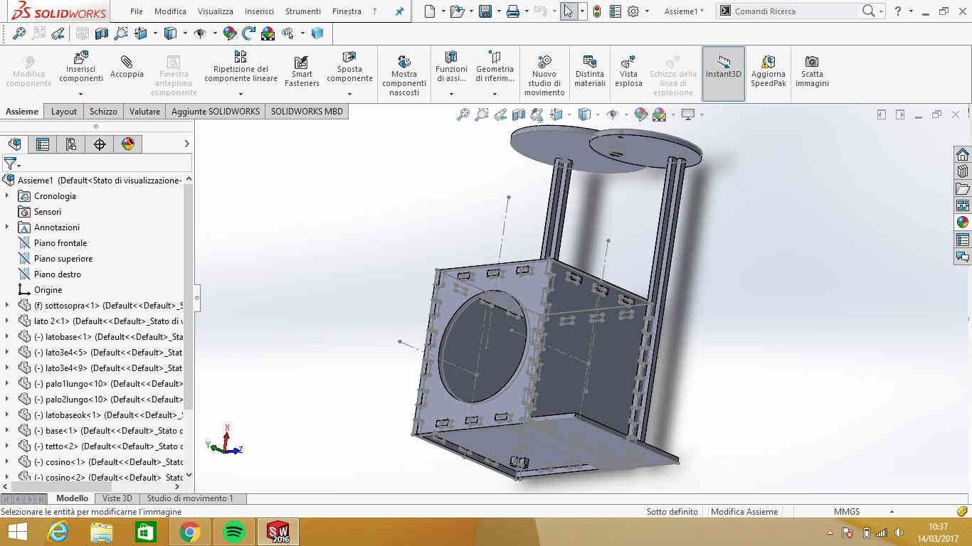 The result is that I made it so big that all my three cats coud enter it together and maybe also my brother's dog (Alpenlaendische Dachsbracke) and
also the shape opens the way
for interesting interretation I'll report some steps forward.
The result is that I made it so big that all my three cats coud enter it together and maybe also my brother's dog (Alpenlaendische Dachsbracke) and
also the shape opens the way
for interesting interretation I'll report some steps forward.
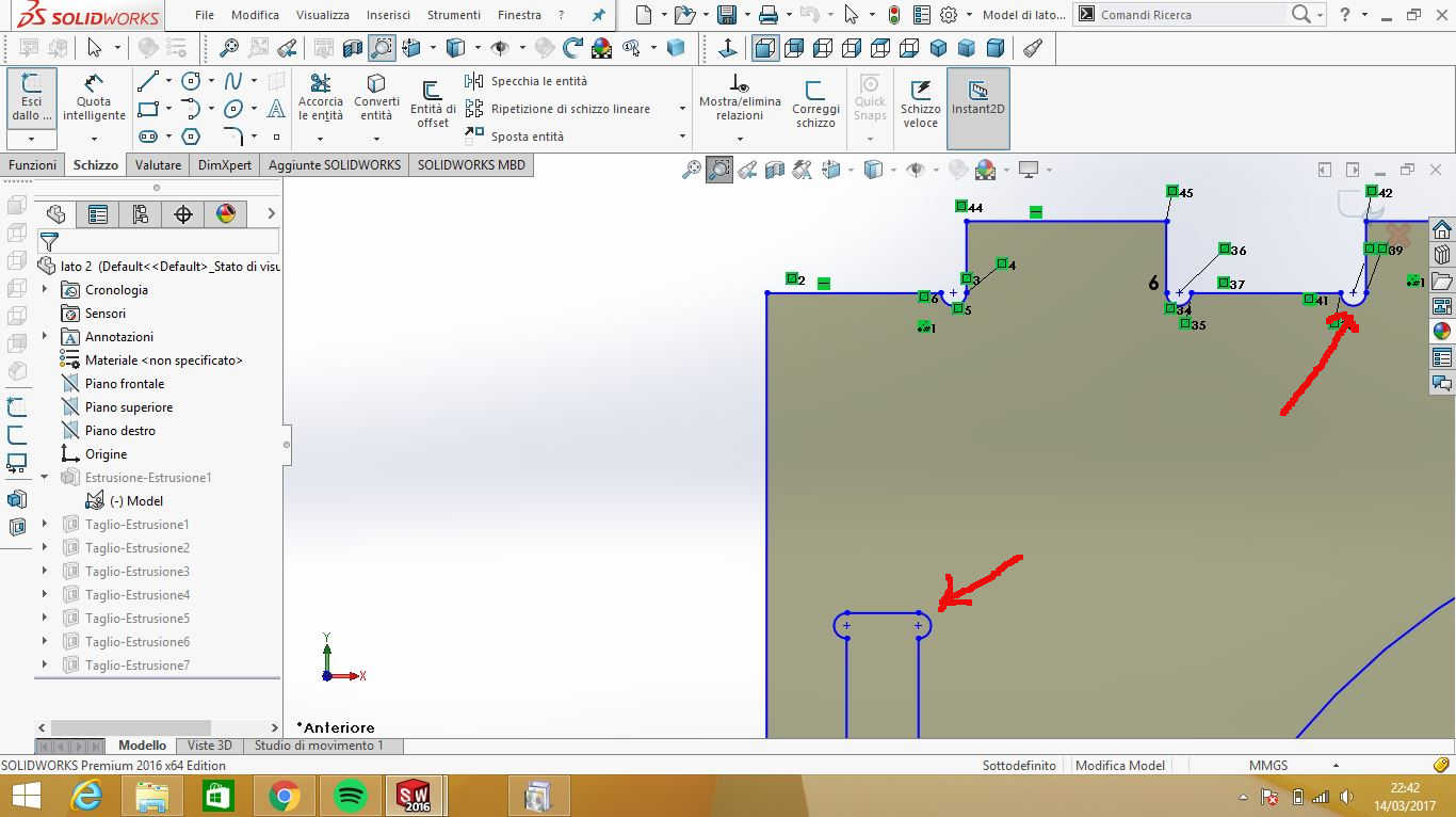
NB: in designing you have to consider adding T-bones (semicircular shapes with diameter equal to endmill one)
to joint female and male edges because otherways endmill will leave
a quarter of circle shape in corners. You can as well add dog-bones (4-corners T-bones) also from Vcarve as explained here.
Second day: Prototyping and getting to know Shopbot
Prototyping
The second day I wanted to have an idea about how my model looked like in reality and I decided to scale it so as to built
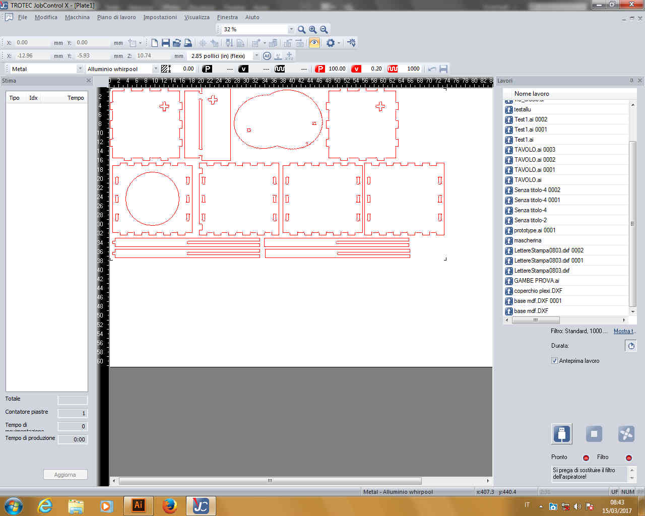
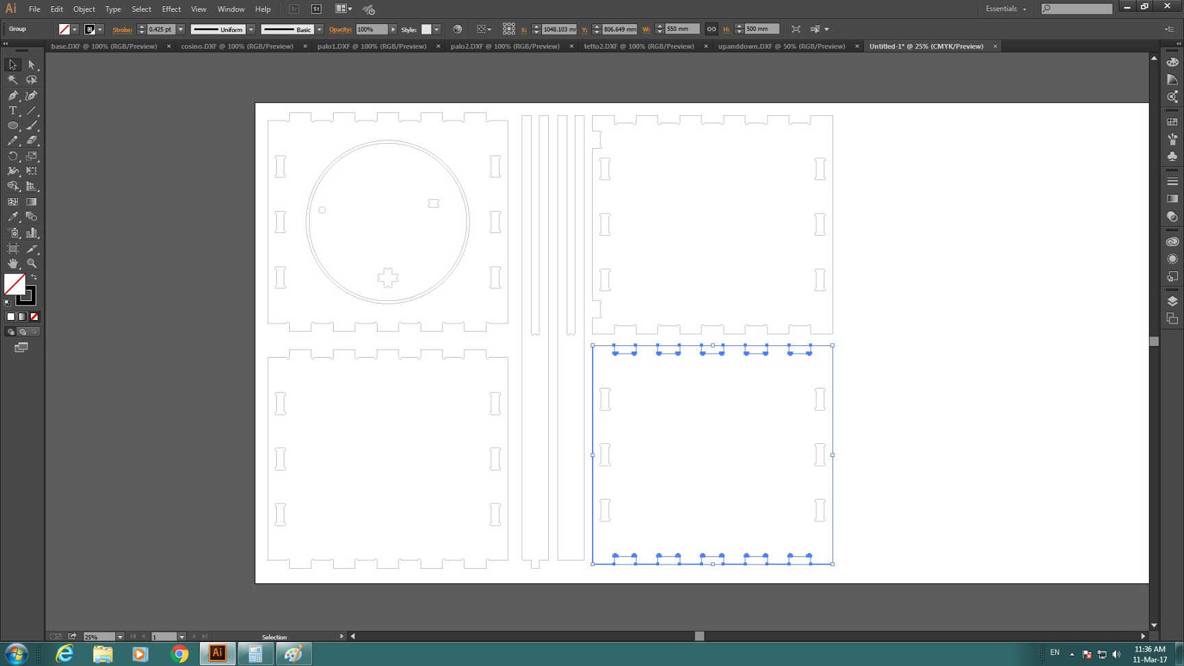
a little prototype. So I exported all model components as a .dxf and opened them on Illustrator.
I put them on the same canvas (which I sized as OSB board dimensions) to see if they all entered the board (I had only one I could use).
Fortunately, every piece entered the limits, also when I scaled canvas size a bit to leave room to screws I'll had to use to block
OSB board.
To scale properly the design (which means scale it of a quantity that could fit joint perfectly) I simply used a mathematical
proportion:
So, as explained in week 3,
I edited line colour and dimensions to as to send it to the laser cutter with Job Control
software.
 In the end my prototype looked like this:
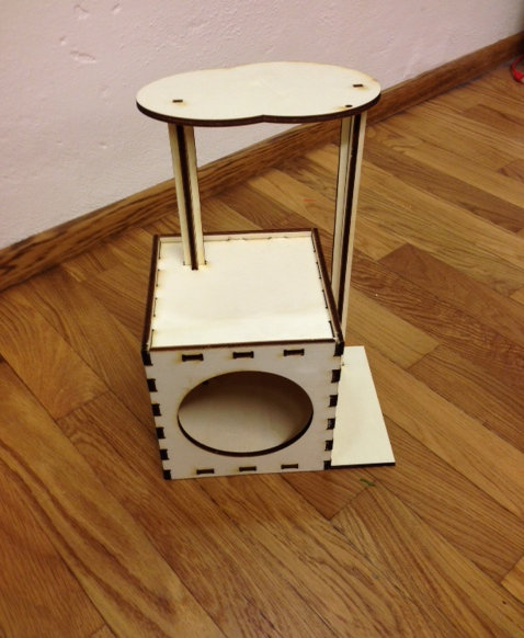
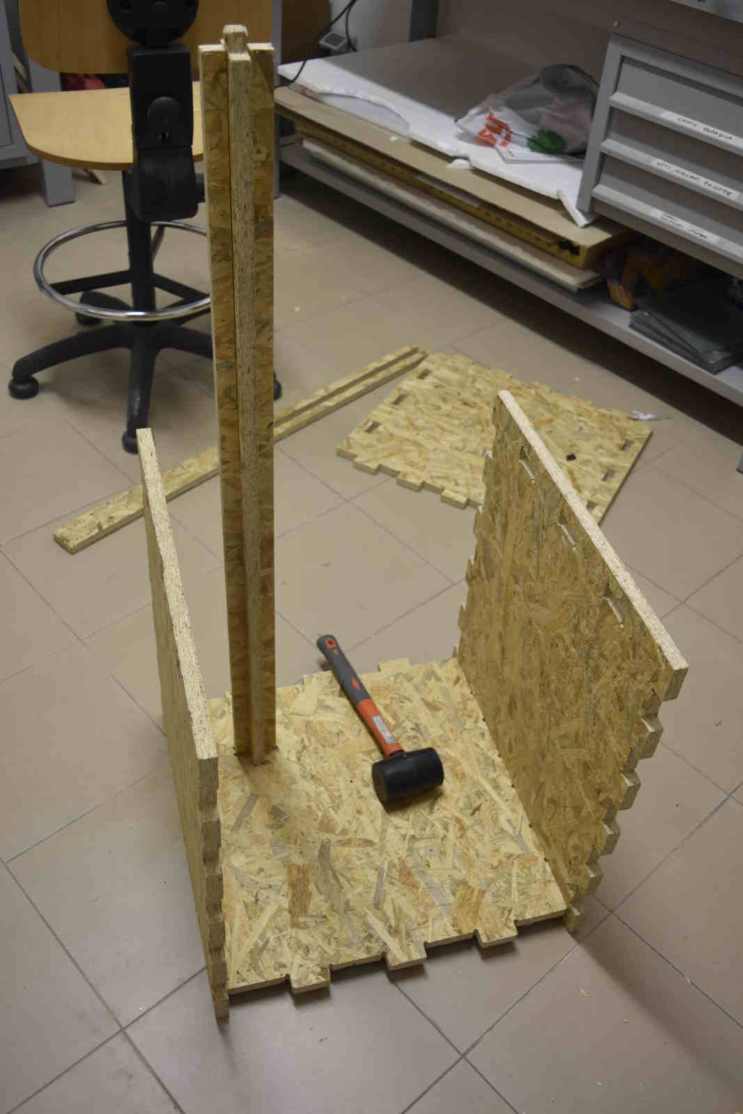
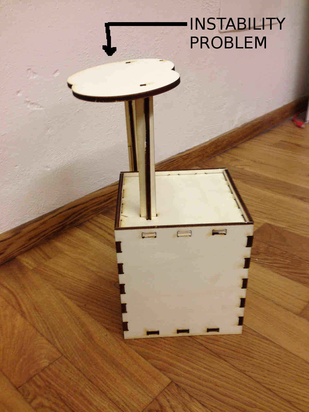 As you can see, I had a bad issue with instability on the upper part so I changed the model and I got to definitive shape:
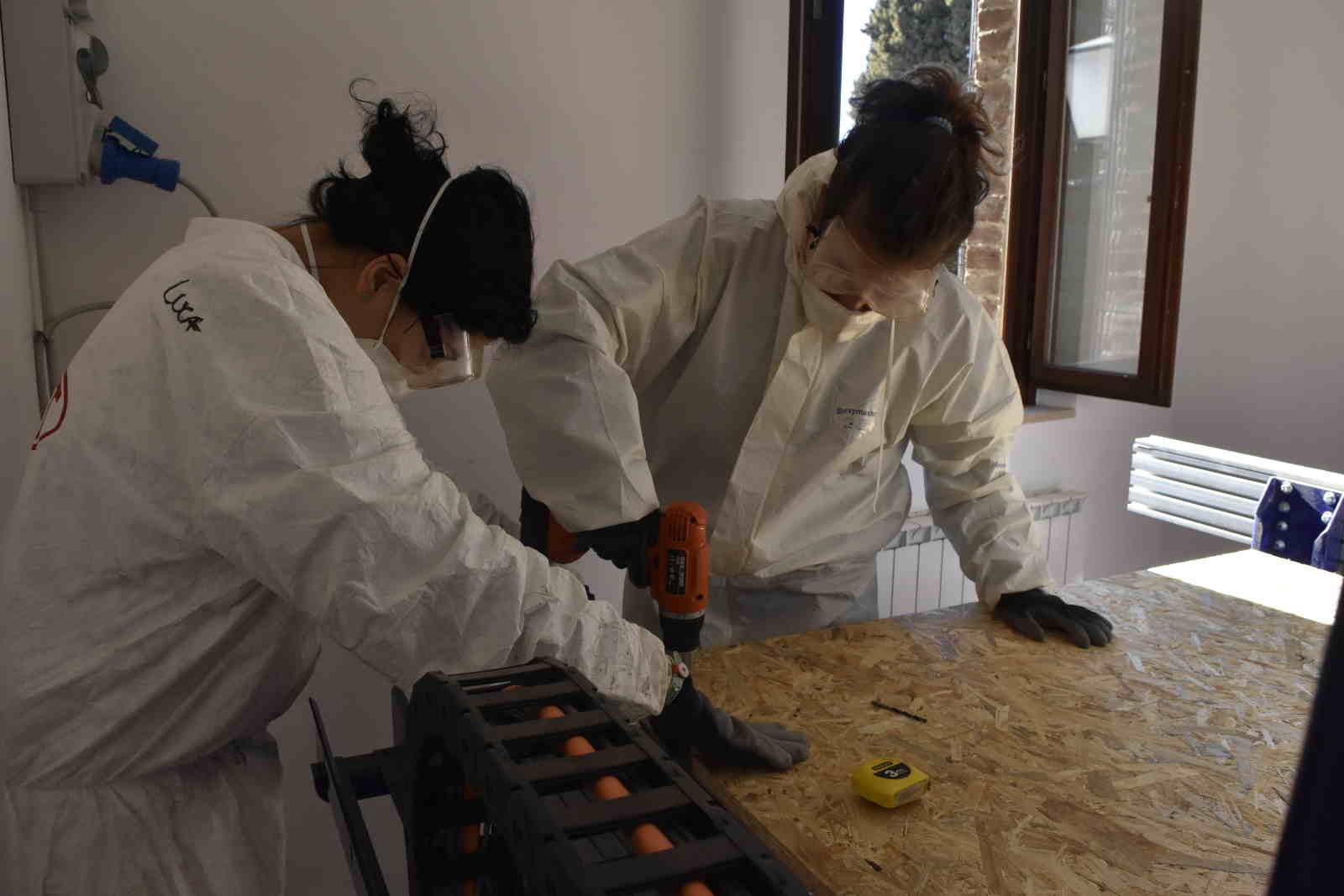
Helping a mate and Parameters setting
In the afternoon, one of my lab mates ( Chiara Corbo) was ready to cut her model with Shopbot
and I helped her in process development.
WARNING: with Shopbot you can die. It is important to be really careful.
Before working, always check you have:
- worn a coverall
- put on safe glasses and mask
- found a friend to help you
- shown him/her your files - double check from external point of view can discover mistakes better
- prepared materials
- tied your hair in a ponytail
...and you can also feel like a ghostbuster for free ;)
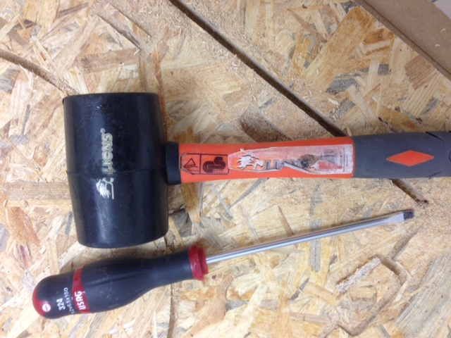
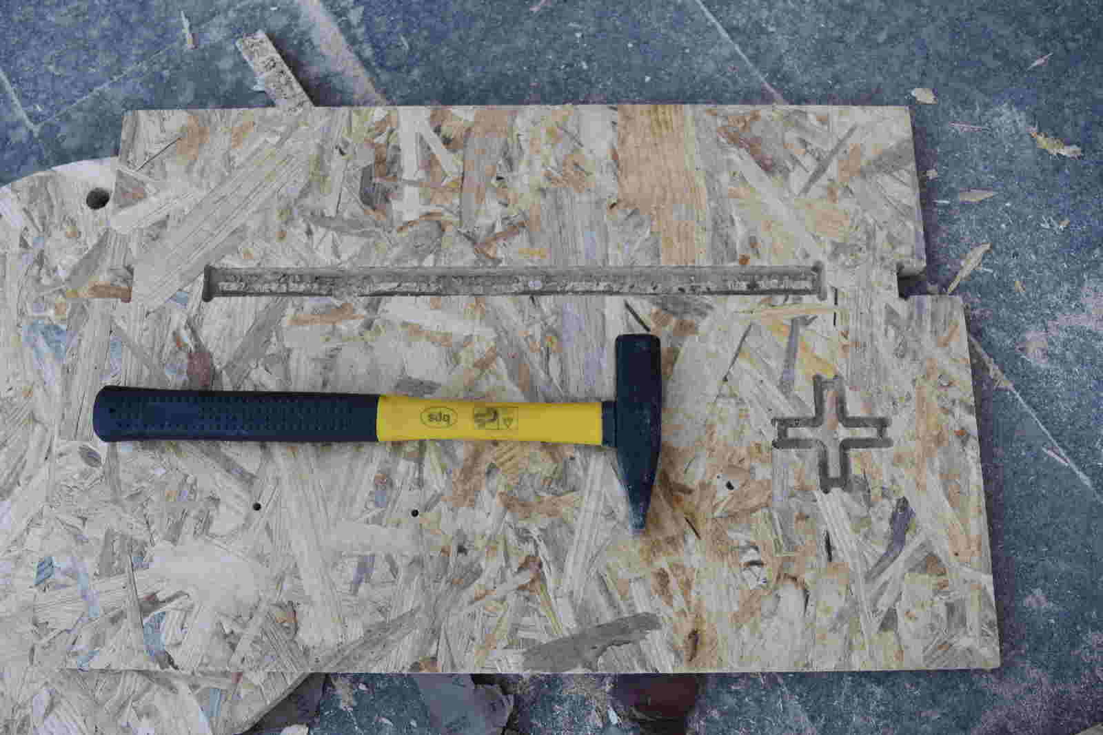
 Materials I'm reffering to are:
- OSB board
- washers and screws to block the board to sacrificial MDF layer
- drill
- screwdriver
- hammer
Then it comes to file preparing and to value settings for Shopbot.
I will explain how to get to Vcarve with my files explanation but without caring much about when
to use info I'll soon provide, let's focus on what they really are.
I'm talking about:
- Feed rate
- Chip load
- RPM
- Cutting edges
Feed rate: it gives you an idea of how fast the endmill moves- for Shopbot it is inches/min.
RPM:("Routes Per Minute") indicates spindle speed.
Cutting edges:number of cutting profiles - you can count them orthogonally looking the endmill from the bottom.
Chip load: this parameter tells you how much material is taken away while cutting from sharp spirals
- you can find it in specific tables (which are different for different materials), given the dimension of the endmill;
I found mine here
in 52-900 series row.
NB: series number are written on the upper part of the endmill.
The formula that links all these parameters is the following:
Result we gain was 192 inches/min and that one was limit working-safety value, but when we made tests we had to adjust values:
| Spindle speed | Feed rate | Result |
|---|---|---|
| 12000 | 192 | endmill moving too fast along X and Y axis and "scream" noise |
| 12000 | 150 | still quite bad sound and cut |
| 14000 | 80 | clean cut and good sound |
Third day: it's time to cut
Preparing Shopbot working area
Once you come to best value combination, you need to affix OSB board to MDF sacrifical layer on your machine.
To do that, arm yourself with:
- OSB board
- screws to block the board to sacrifical MDF layer
- drill
- screwdriver
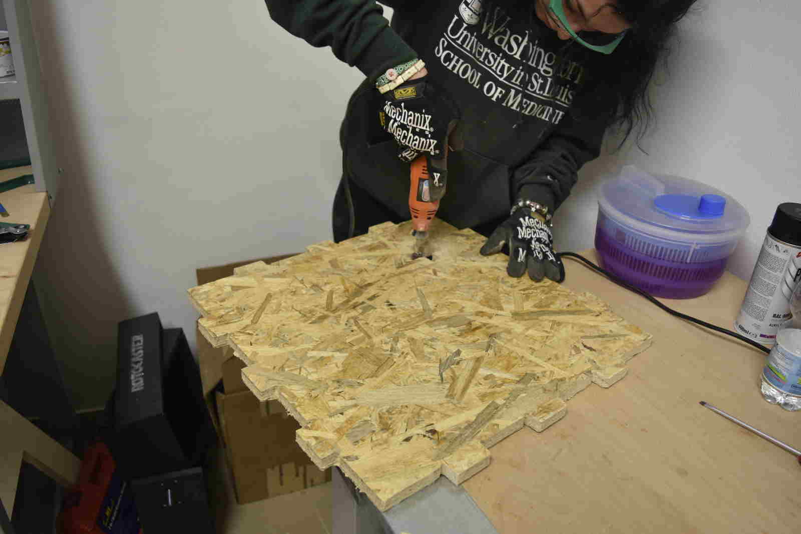
Once you manage to bring the board on the working area and to align it to borders and, using the drill, make some holes close
to borders so as to use them for screws. (if OSB board is bigger than MDF sacrifical layer
align at least two edges and be careful to drill where OSB touches MDF).
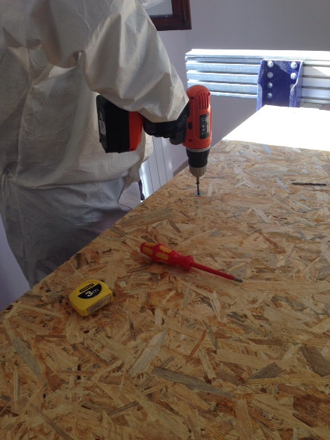 TIP: before drilling it's always better to make signs on the board and launch test cut to see if
the endmill hits washers or screw top part.
TIP: before drilling it's always better to make signs on the board and launch test cut to see if
the endmill hits washers or screw top part.
WARNING: it is very important to stay at least 10mm away from washer edge cause if the endmill hits a
metallic part while cutting, it will break and beside economic damage (endmills for Shopbot cost quite a lot) there's also
a huge safety risk because parts that will detach from endmill will bolt away from worKing area with high speed and if it clashes on your body
it will go through your skin.
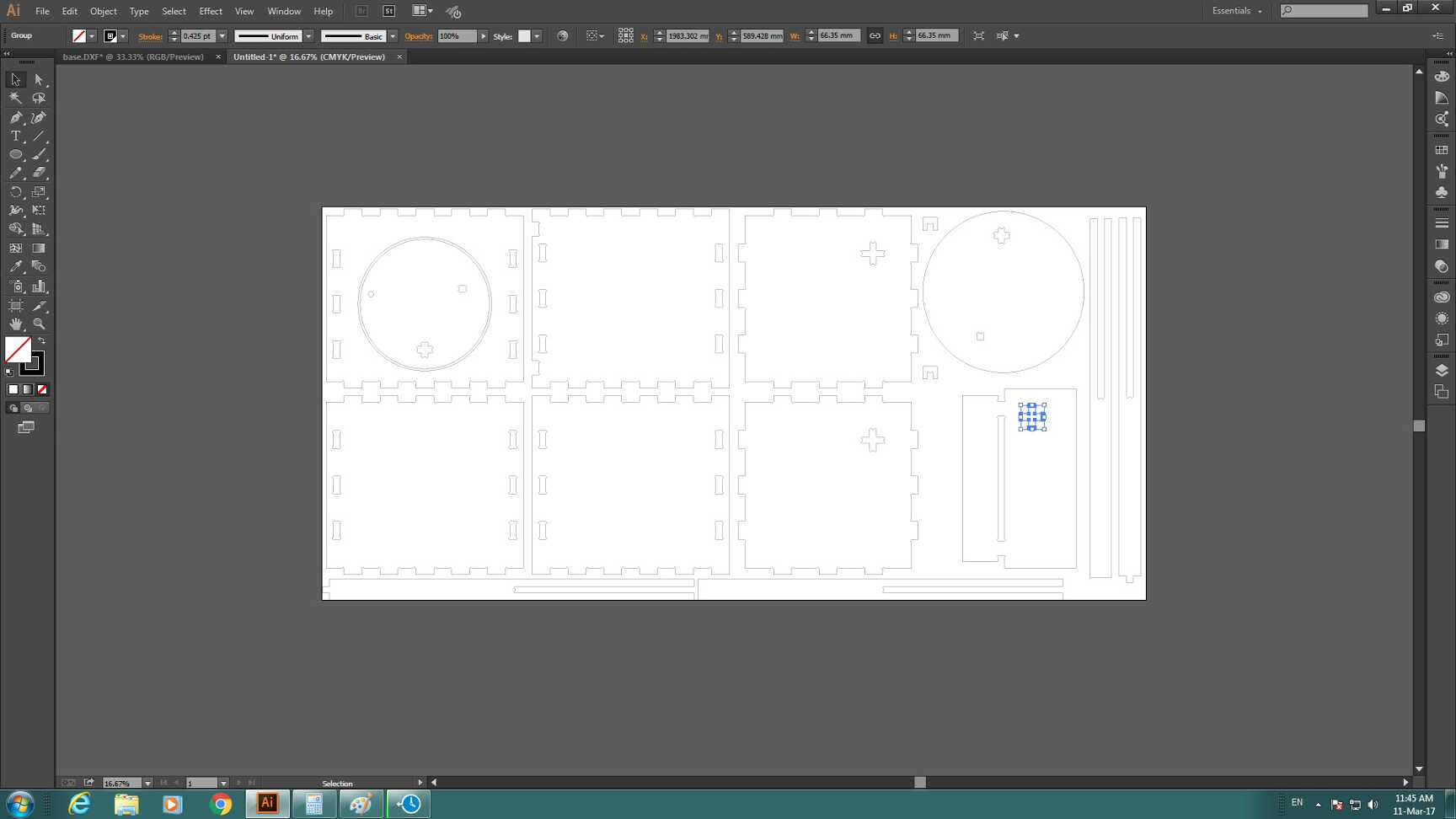
When I put all parts .dxf on the same file I realised I had very little space left between cutting edge and OSB
board edge, I decided to put some screws in inner parts (I had several rectangulare shapes with 500x550 mm area and other no-inner-cut areas, so
I cpuld do that). This trick requires to be ten times more careful in avoiding screw-endmill hit, so it takes me several cut test to choose
screws right position.
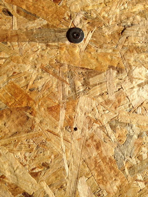
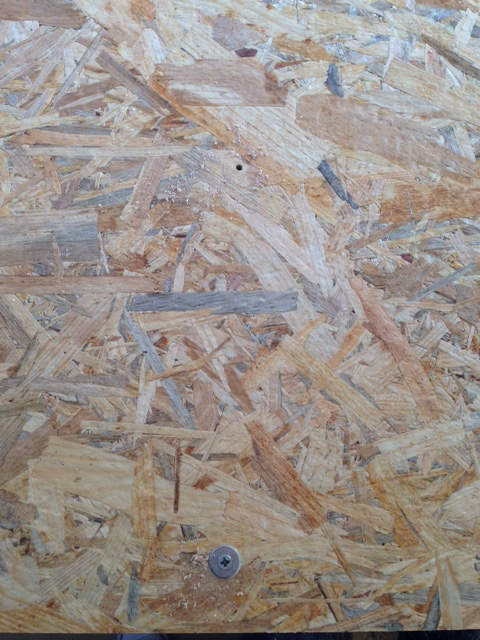
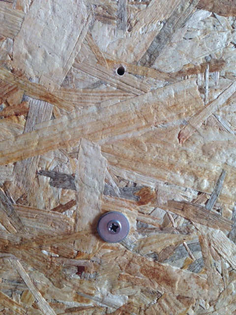
Below I show where I did put screws relatively to my design:
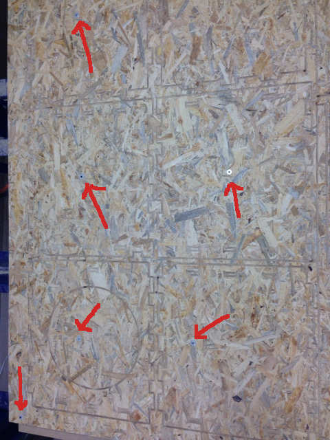
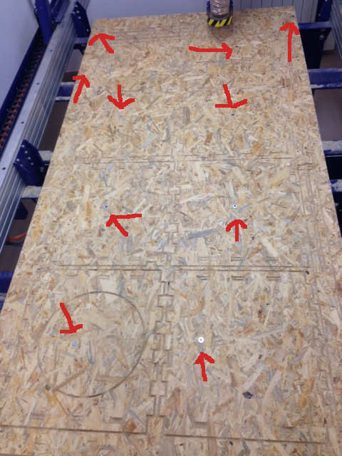 ...and still I didn't take a picture of all of them.
Do you think they're too many?? I think not, because it's really important to attach the board in all those area thay may
implicate material detachment and dash. And....
...as my instructor (try to) say - No, he's not named Seneca.
As I said, it is important to send test cut to see if you placed screws well, so let's see how to do it.
Prepairing files with VCarve
To prepare file to be sent to Sb3 -Shopbot software-, I used VCarve.
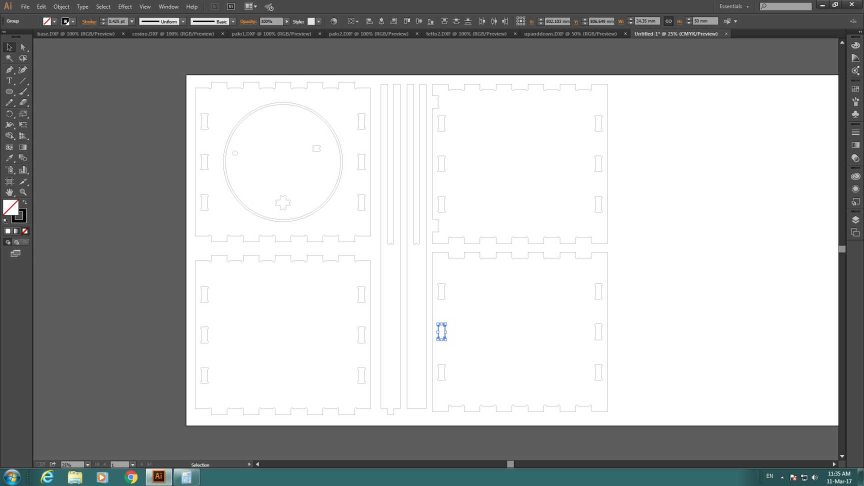
Before facing with it, it is needed to open all your .dxf files on the same Illustrator file, setting canvas sizes
as the ones you'll have available on OSB board after attaching it with screw.
Here you have to do basically two things:
- join contour lines;
- check joint dimension exactly corresponds to material thickness
- export a .dwg file
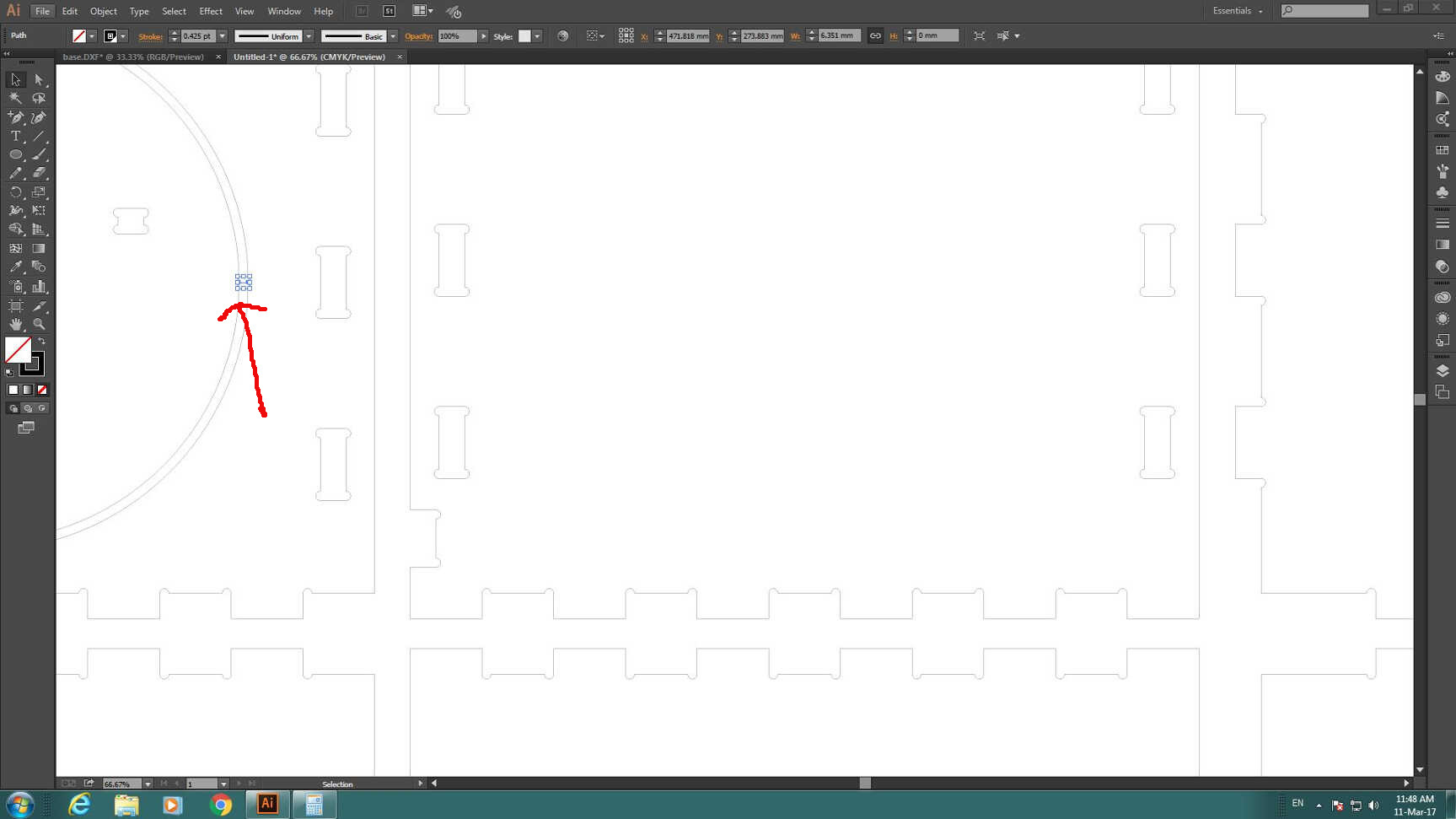
To do this last action, you can simply draw an othogonal line between joint edges and see its dimensions:
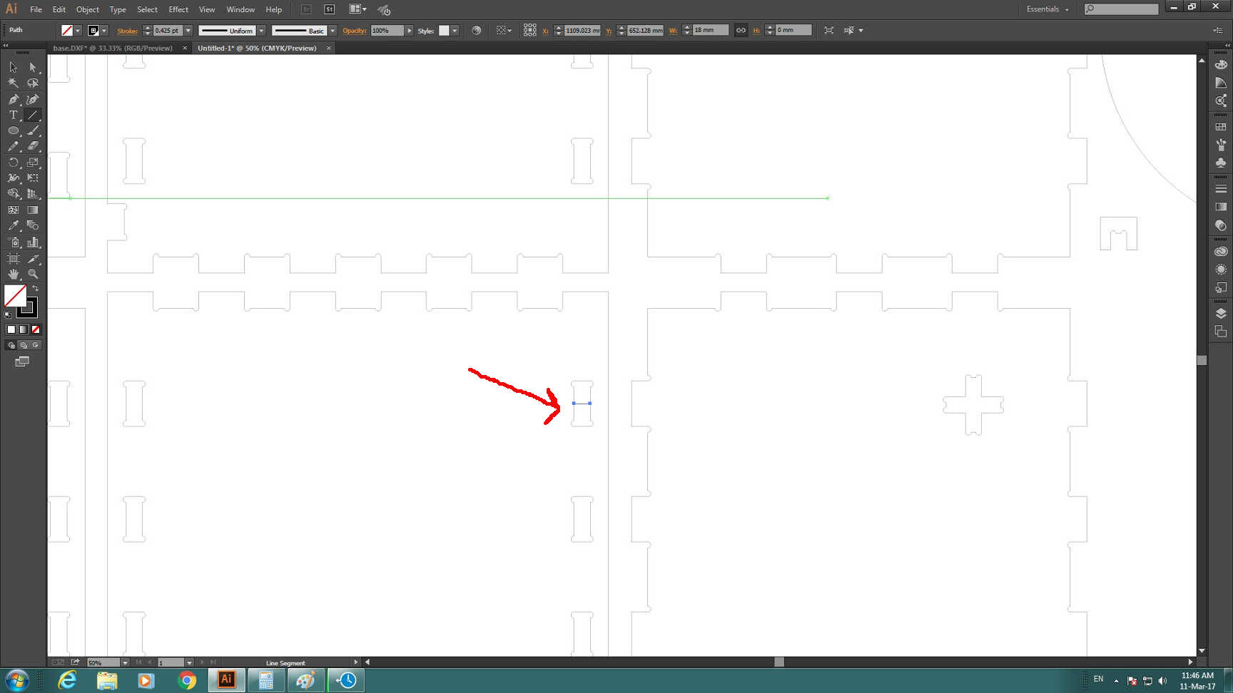 ...and repeat this for all joints. I had to repeat this action also for a circle that has to be cut inside another part, so
I checked the distance between the two parts was at least endmill diameter.
...and repeat this for all joints. I had to repeat this action also for a circle that has to be cut inside another part, so
I checked the distance between the two parts was at least endmill diameter.
 NB: cutting a part inside another can look scary due to detaching of inner part risk, anyway it helps a
lot in space saving and less material wasting.
NB: cutting a part inside another can look scary due to detaching of inner part risk, anyway it helps a
lot in space saving and less material wasting.
To join edges you have to select separately all contour lines and press Ctrl+j.

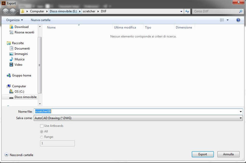
 Then, las thing you have to do is to export your work as .dwg file going through File-->Export and selecting .DWG
format in the "Export" window.
Then, las thing you have to do is to export your work as .dwg file going through File-->Export and selecting .DWG
format in the "Export" window.
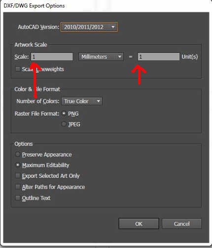
 After clicking on Export a new window will open, check parameters are set like this:
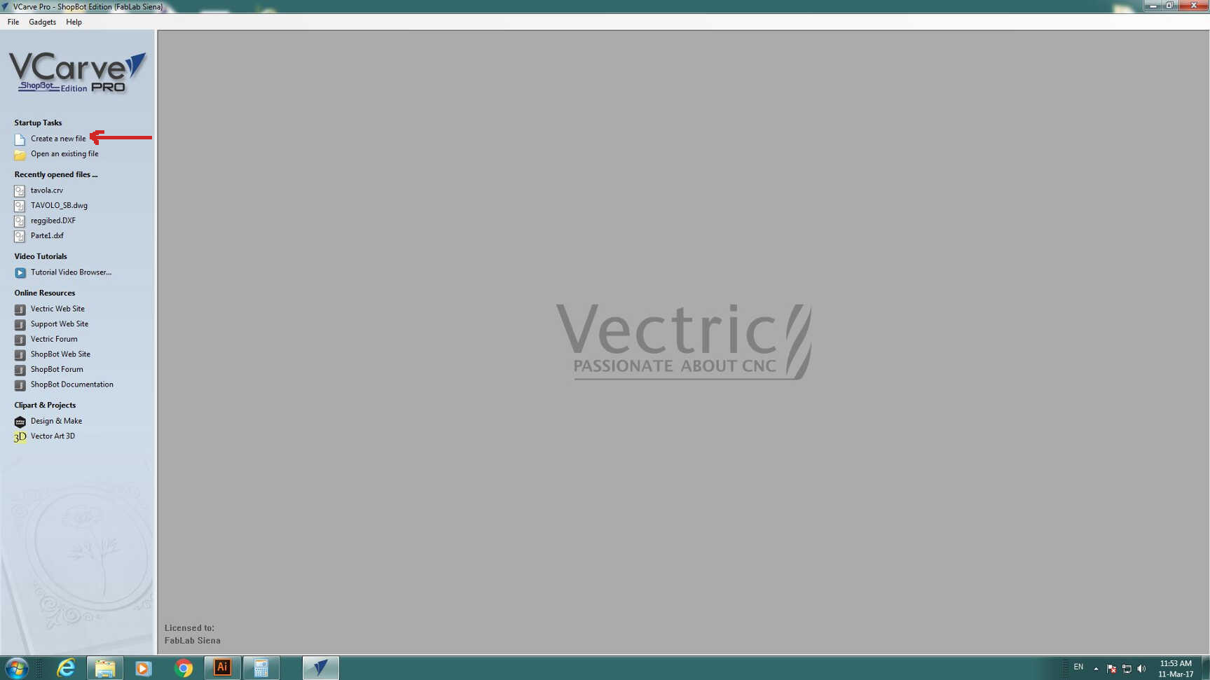
 I then opened VCarve and clicked on Create new file:
 Then a new window opened and I had to set some values:
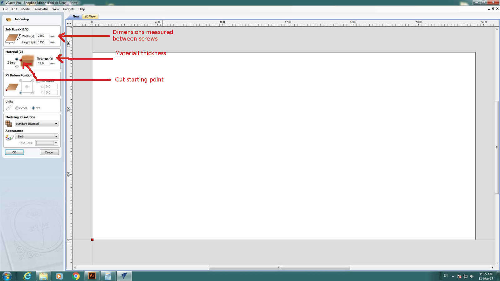 NB: Check your machine orientation relatively to your position: in my case for example, machine was oriented
orthogonally, so x axis on computer was y axis on reality
NB: Check your machine orientation relatively to your position: in my case for example, machine was oriented
orthogonally, so x axis on computer was y axis on reality
IMPORTANT: not to scare you, but each single setting parameter has great importance for safety, so be sure you
surely now how to set it.
I so clicked on OK and in new VCarve file I imported .dwg file clicking on Import vector froma file icon:
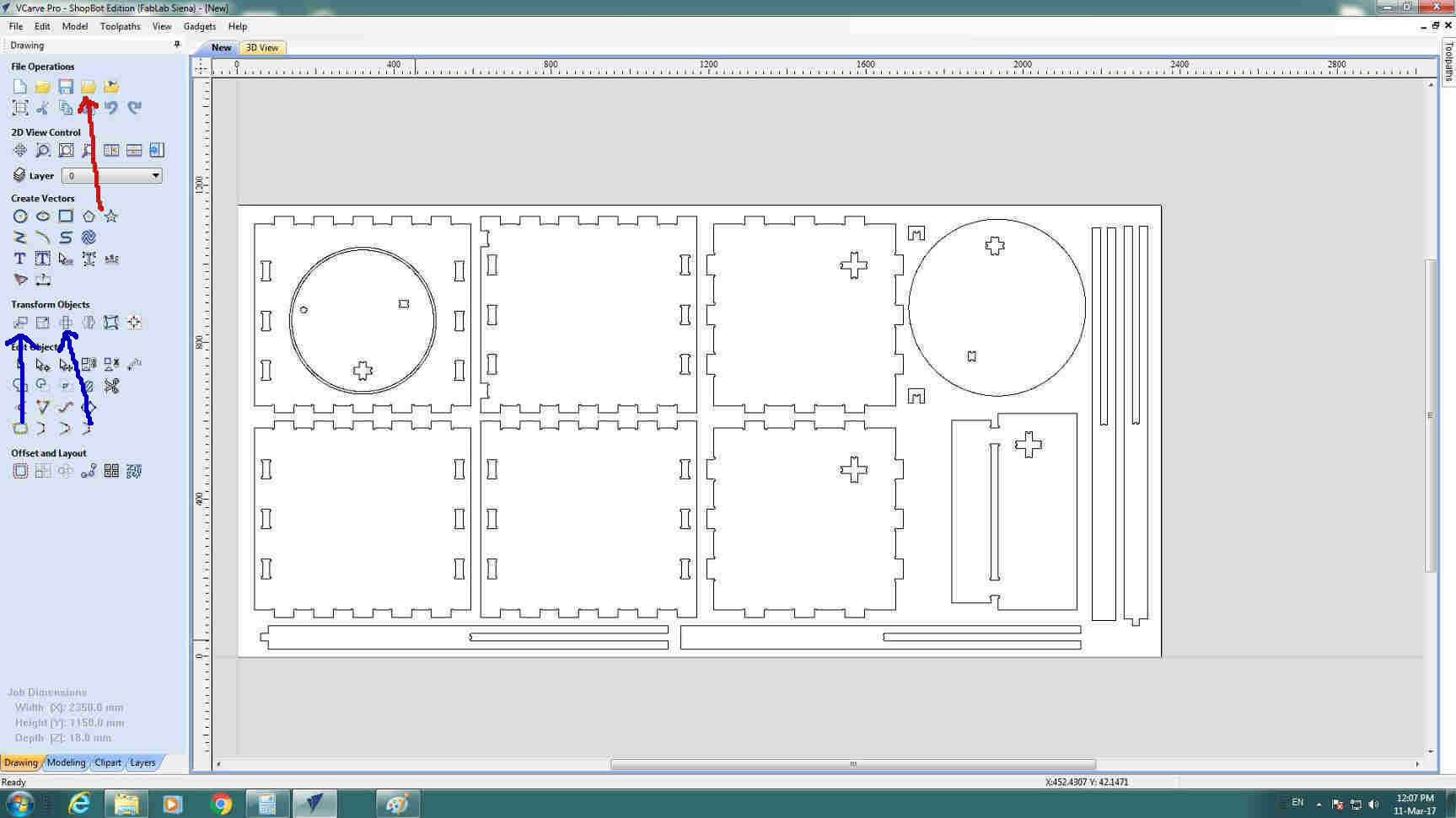 With blue arrows I indicated buttons with which you can move and rotate your design in canvas area.
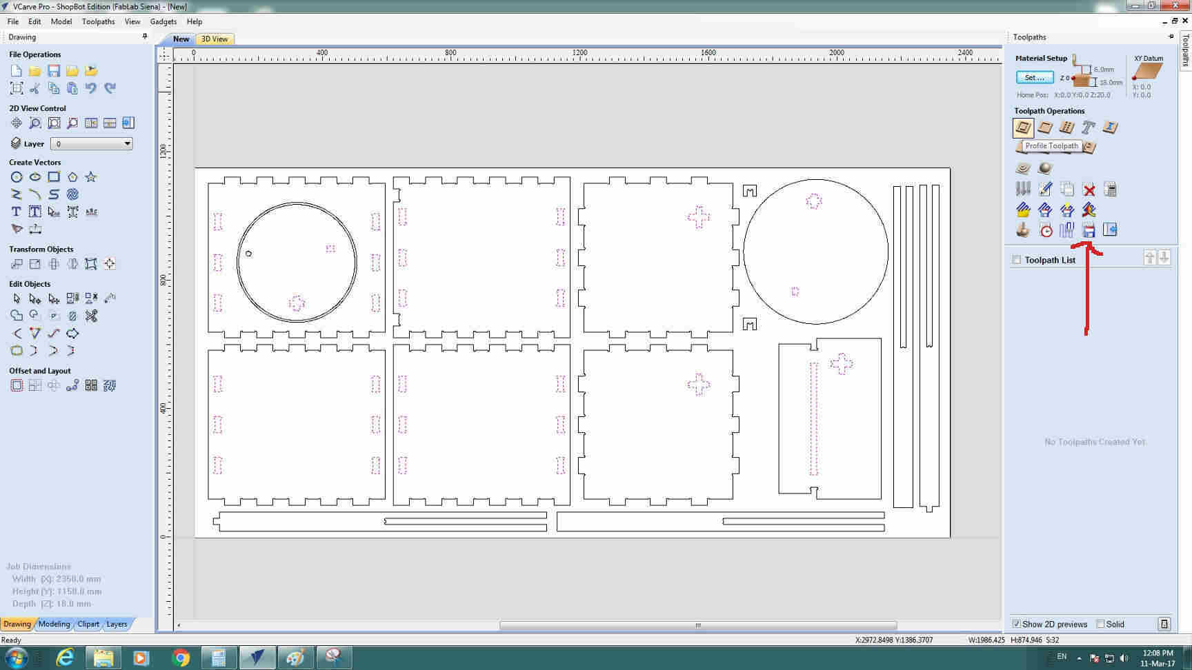
Then I started from inner cuts (which has to be performed first). So I selected part of interest and opened Toolpath
window from the upper part of the working space and I there selected Profil Toolpath icon:
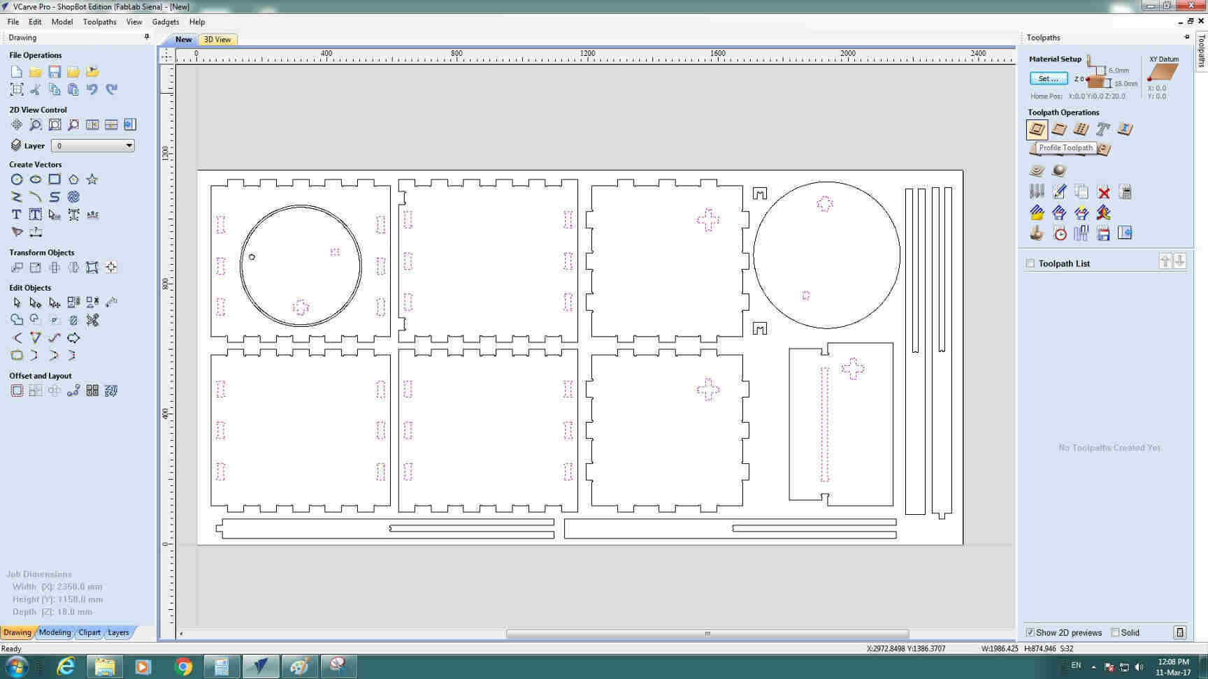 NB: why Profile Toolpath icon I could have chosen Pocket which differs in the fact that
all inner material is removed -while instead Profile tool just cut the edge and leaves material inside- but it would have taken
me a lot more time for the same result.
NB: why Profile Toolpath icon I could have chosen Pocket which differs in the fact that
all inner material is removed -while instead Profile tool just cut the edge and leaves material inside- but it would have taken
me a lot more time for the same result.
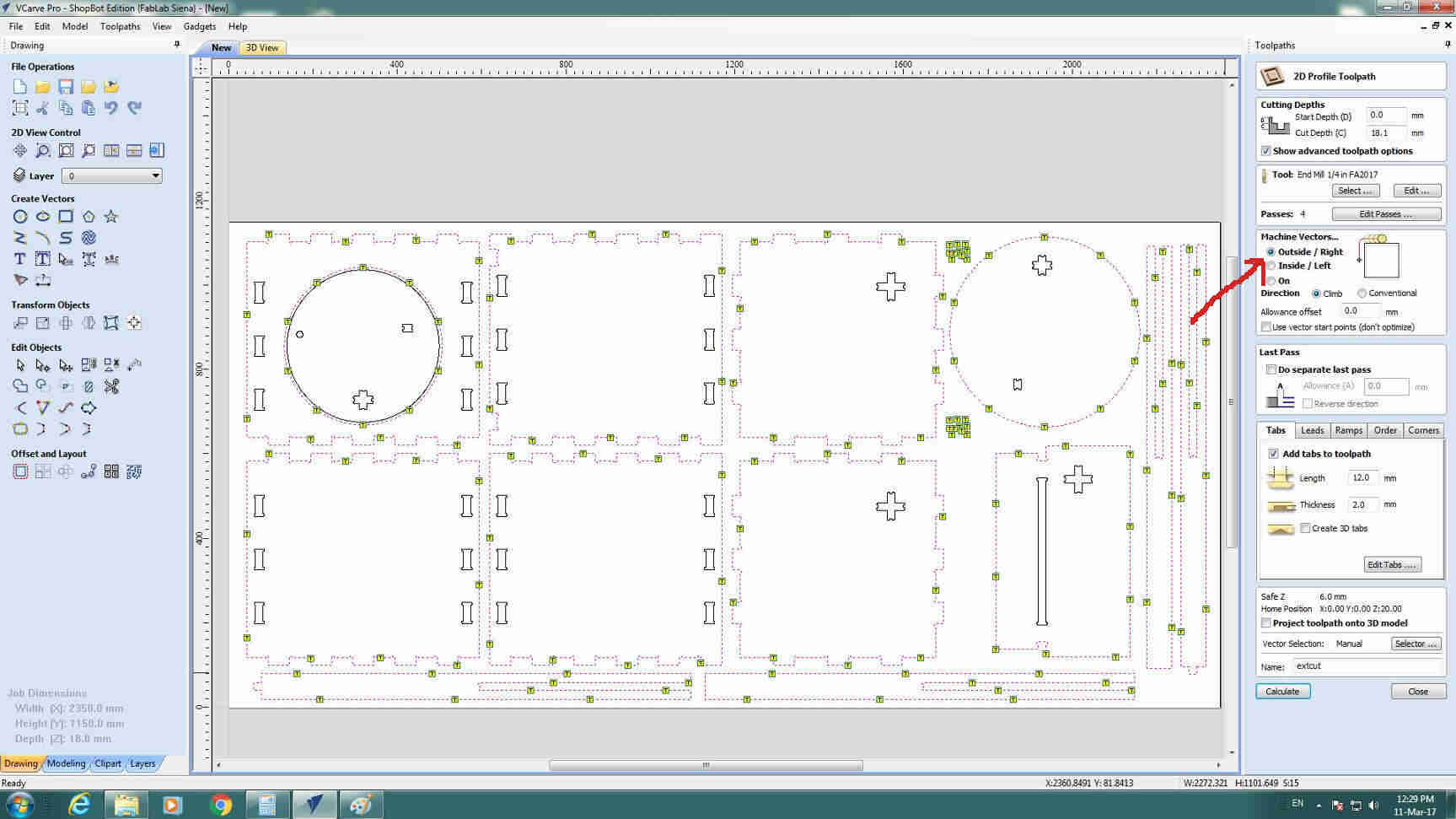
I then started setting all values:
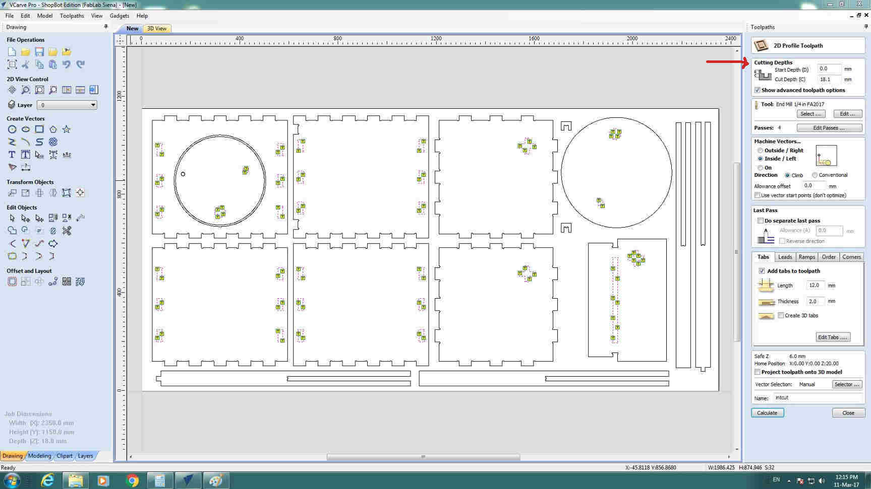 Cutting depth: my OSB board was 18 mm high but I added 0.1 mm (practically nothing) because in some points of the board,
due to irregular finishing of material, height could be different.
Cutting depth: my OSB board was 18 mm high but I added 0.1 mm (practically nothing) because in some points of the board,
due to irregular finishing of material, height could be different.
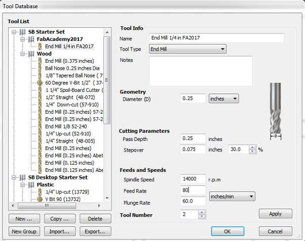
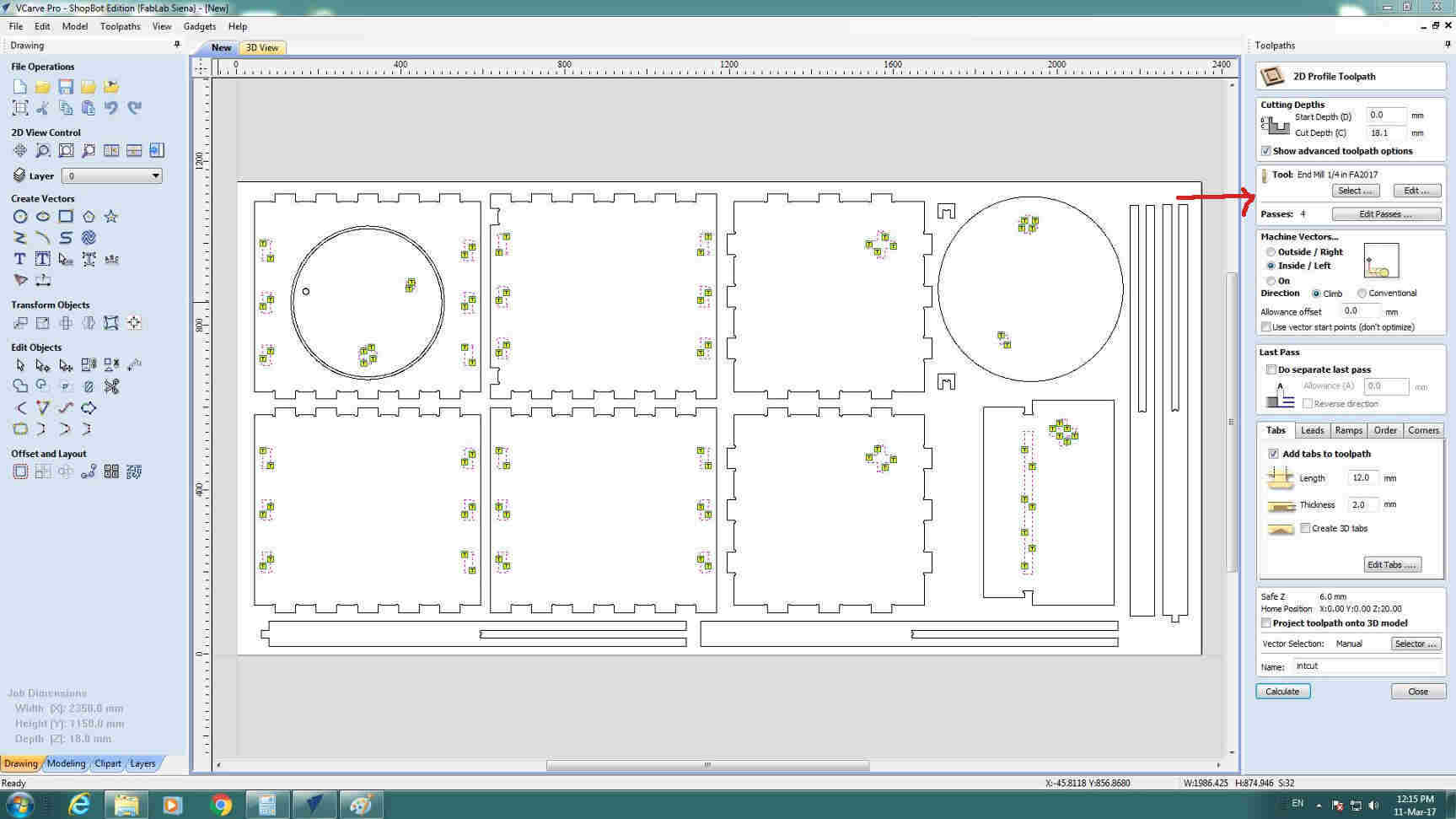 Tool: clicking on Select button I created a new voice for my 1/4 inch endmill with parameters
calculated and tested before (Second day)
Tool: clicking on Select button I created a new voice for my 1/4 inch endmill with parameters
calculated and tested before (Second day)
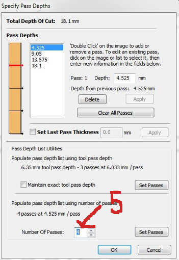
 Also in Edit passes I changed from default value (4) to 5.
 Then in Machine vectors.. I chose Inside/Left voice to have inner cut and Climb direction - which means rotation
goes in the same direction of translation of speed.
Then in Machine vectors.. I chose Inside/Left voice to have inner cut and Climb direction - which means rotation
goes in the same direction of translation of speed.
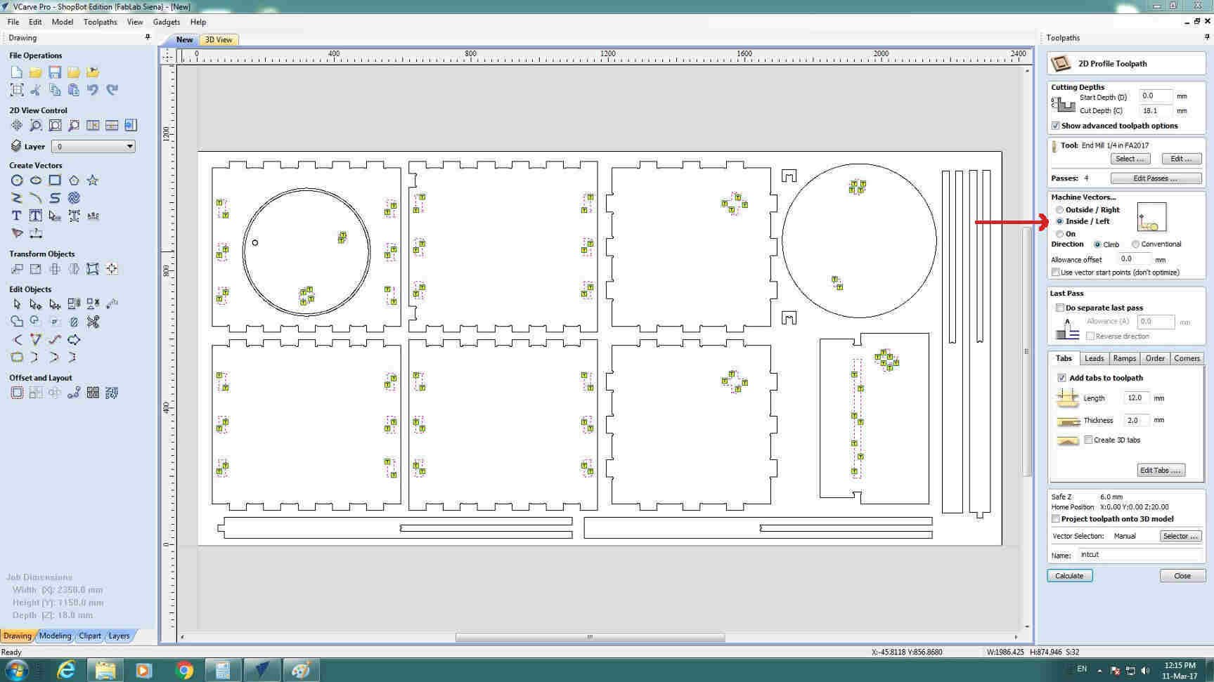 Then I edited Tabs window:
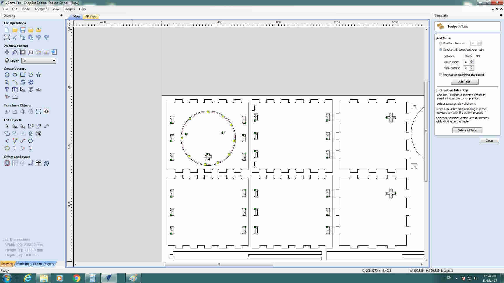
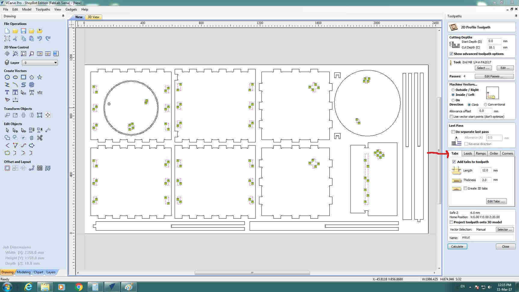 I editet tabs leght and thickness and I clicked on Edit tabs.. button to edit their number:
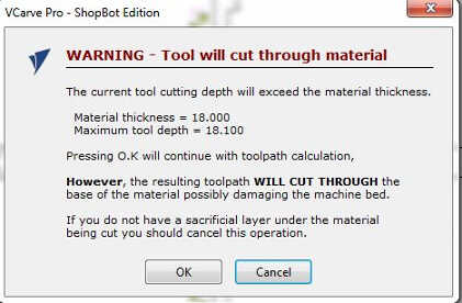
 So, after double checking all parameters were well set, I changed project name and pressed on Calculate.
If you, a I did, set cutting depth higher than material thickness, a warning message will appear but you just have to click on Ok
 Once you saved your file you can have a preview of cutting process:
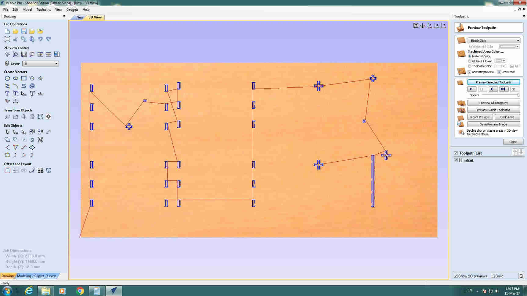 (Here I forgot to add the circle to cut file)
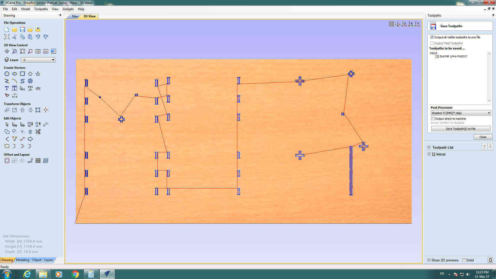
Then click on Close button and save file from the Save Toolpath icon:
 In new window check Post processor voice is set in MM (if you designer your worked in mm) and that Output direct to machine
is unticked (otherwise your machine ould start cutting immediately).
In new window check Post processor voice is set in MM (if you designer your worked in mm) and that Output direct to machine
is unticked (otherwise your machine ould start cutting immediately).
 I repeated all these actions for external cut paying attention to set Outside/Right choice in Machine vectors
window.
I repeated all these actions for external cut paying attention to set Outside/Right choice in Machine vectors
window.
You can use these file for testing but you can either make new files with just 1 passes (Passes-->Edit Passes..)
to quickly see if you are going to hit screws or not.
IMPORTANT: test test test and test another time! I made tests twice both withouth and with screw inserted
because despite seeming a waste of time is a gain on security!
Sb3:cutting tests and process
Finally direct experiene with Shopbot.
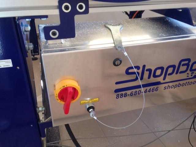
NB: before proceeding check spindle is turned off....How? On the right of your machine, there's a red
lever - which has now to be in ON direction- and a key. The key is linked to a strange wrench which is needed for changing
endmill: this trick helps in that you won't be able to put your hands on the endmill if the spindle is turned on. To turn off the
spindle simply remove the key.
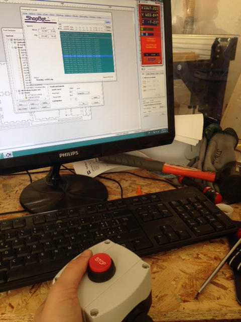
 When you open Sb3 -Shopbot software-, a position panel opens:
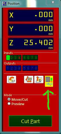 From that nintendo-shaped yellow button you can access keypad panel.
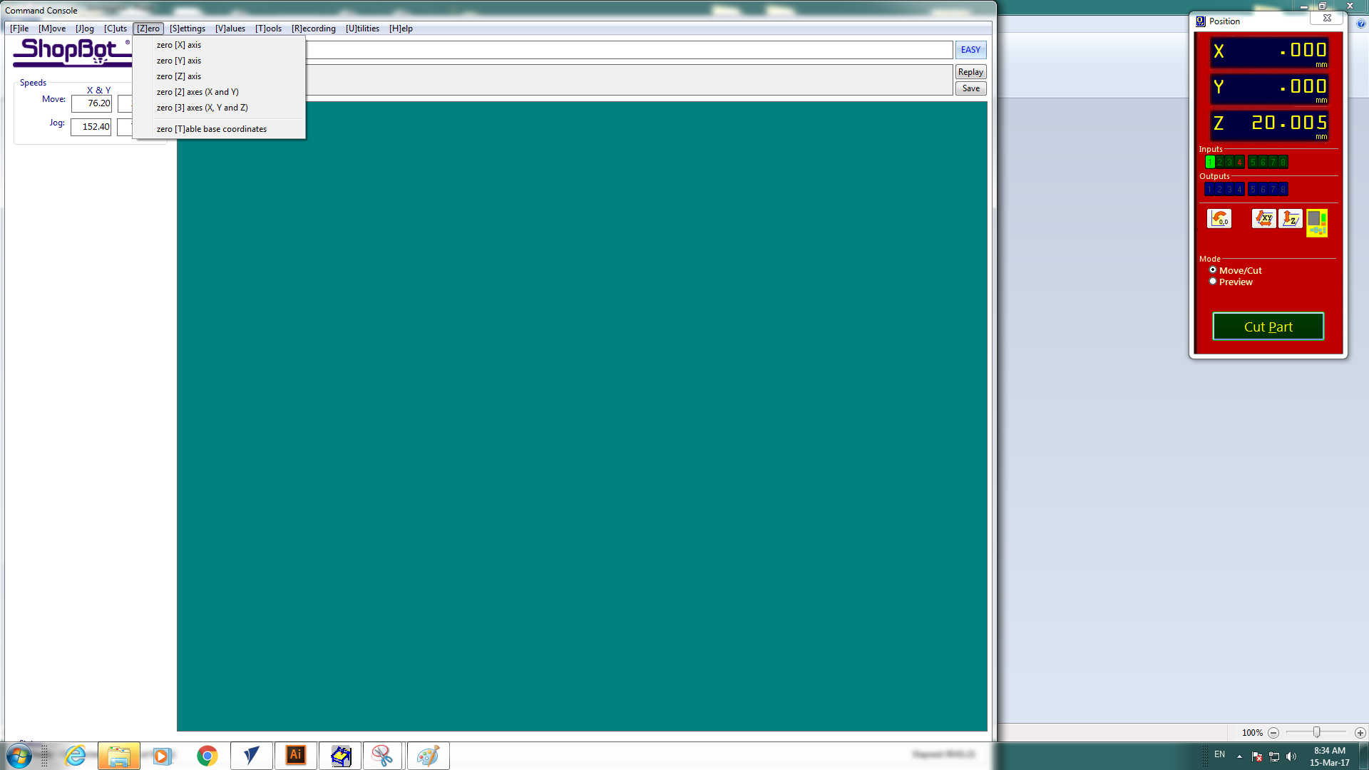
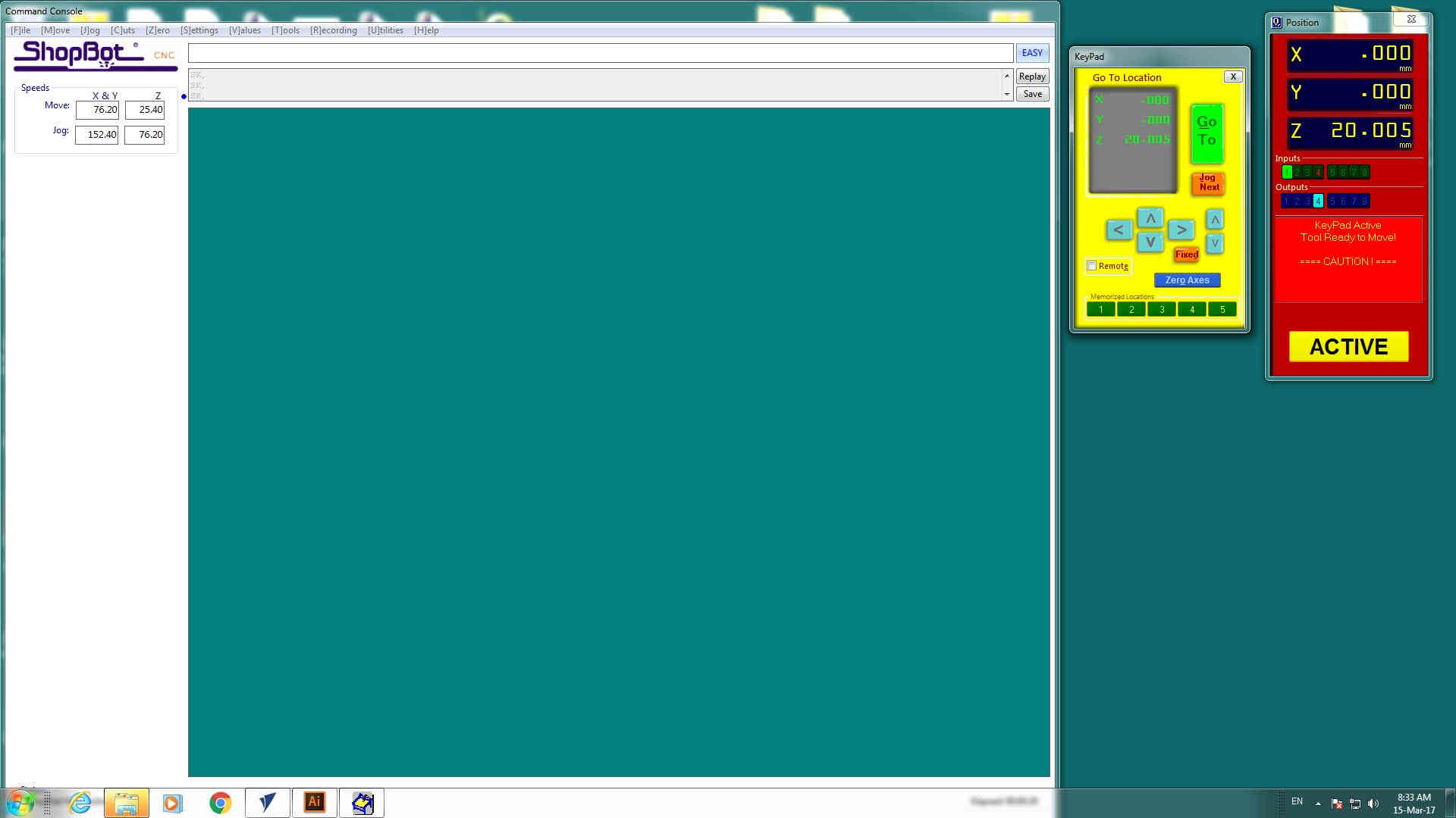 What you want to do now is to set X, Y and Z axis origin. To do that you have to:
- move the spindle with arrow buttons till you reach the position desired, paying attention to leave room enough for screws.
- go through Zero--> zero [X] axis
- repeat this action also for y axis
 For z axis there's another way to set 0 position for definitive cutting. But let's now expose how to set it for test cutting.
Considering that you already set material thickness, in 1 passes, the endmill will directly go that deep, so remeber that in setting safe
height (I left 8-10 cm from board surface).
So, once you set all your axis origin (z safe height), you can go through File-->PART FILE LOAD and select your test cutting
files and press on START in position panel.
NB: Why didn't you turn on the spindle, Silvia? Just because there's no need to do that, test can
be (and I would say should be) done with turned off spindle.
...Did you see if the endmill passes over an inner screw or too close to a lateral one? Maybe? Not sure?
In my case I had to move some screws:
Now that I checked everything I had no more excuse to postpone my definitive cutting and hidden irretrievable-errors.
So I turned on the spindle (with the key) and went through Cuts-->Spindle Warmup Routine.
 This action helps lubrificant to reach all the spindle parts and it will take 10-15 mins.
NB: NO, it's not coffe-break time! Sit down at proper distance (1,5-2m) from Shopbot and keep
STOP button in you hands - better to stay behind a polycarbonate window like me.
 NB of NB: always do that with spindle turned on and working!
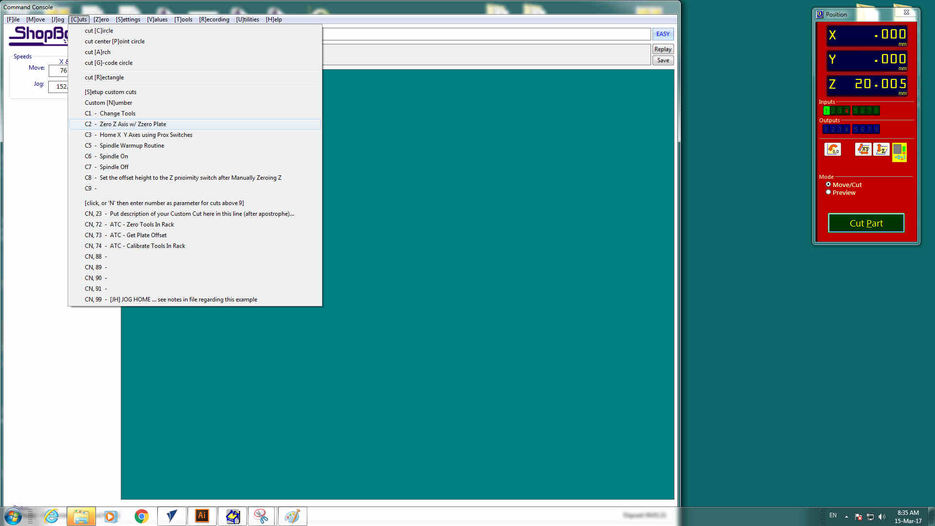
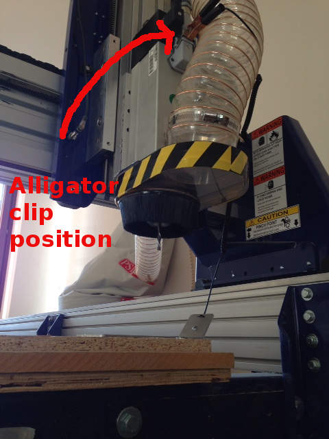
Once warmup is done, it's time to set zero of z axis again. To do that you need to position zero plate under the endmill and the
alligator clip on circuit-closing spot and to go through Cuts-->Zero Z axis w/ Zero Plate.
NB of NB: always do that with spindle turned on and working!
Once warmup is done, it's time to set zero of z axis again. To do that you need to position zero plate under the endmill and the
alligator clip on circuit-closing spot and to go through Cuts-->Zero Z axis w/ Zero Plate.
Zero Plate Setting from Silvia Palazzi on Vimeo
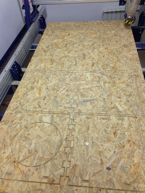
Then turn on the aspirator, have a comfortable seat and launch your definitive cutting file File-->PART LOAD FILE (5 passes one in my case).
I started from inner cut and then launched external cut ...Total time: more than 2h cutting!
OH! I forgot, as Neil Gershenfel recommended, be well fed... and power up ;)
Shopbot Music from Silvia Palazzi on Vimeo
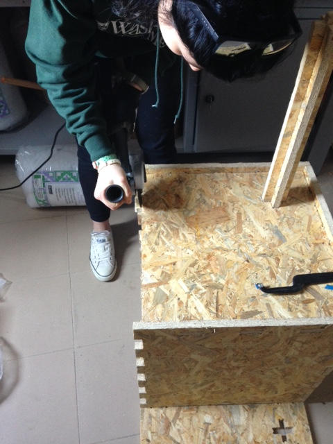
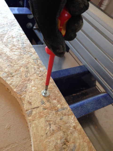
When cutting is finished, arm yourself....
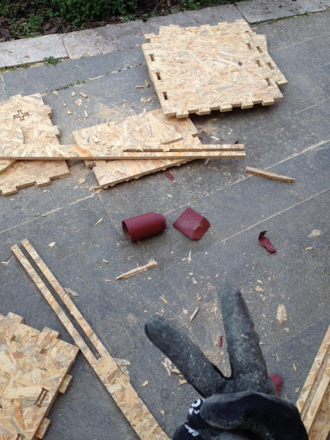
 ...and remove your parts.
 Ok, I admit I was too unpatience to take them away and so I broke two pieces (the little ones) so I already know I would have had to cut
another time with Shopbot.
Ok, I admit I was too unpatience to take them away and so I broke two pieces (the little ones) so I already know I would have had to cut
another time with Shopbot.
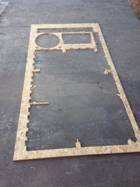
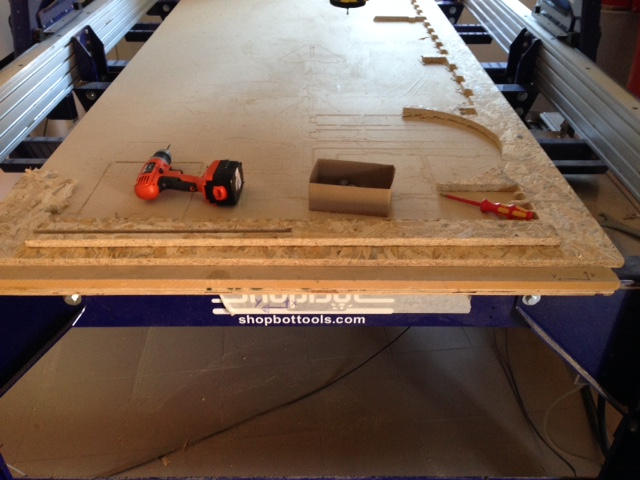
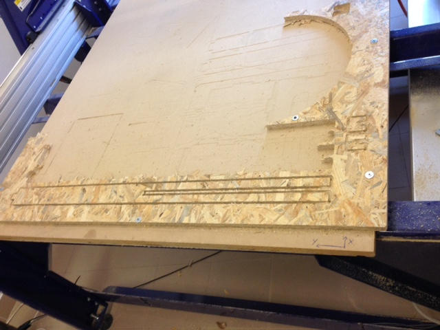
This is what remained of my cut:
Fourth day: the hardest one
You may thought it was almost done
There's always a reason....Also for buying such a patchy wood board that cost as much as other more human-friendly materials.
The reason is the same one that tells you the smartest rich is that one who suffered indigence. This is to say that building something
with an easy-fit material is easy, but in case you can't have that privilege, it's useful to know how to dovetail two parts that don't
want to hear a thing about matching together.
You'll sweat and it maybe will also test your patience.
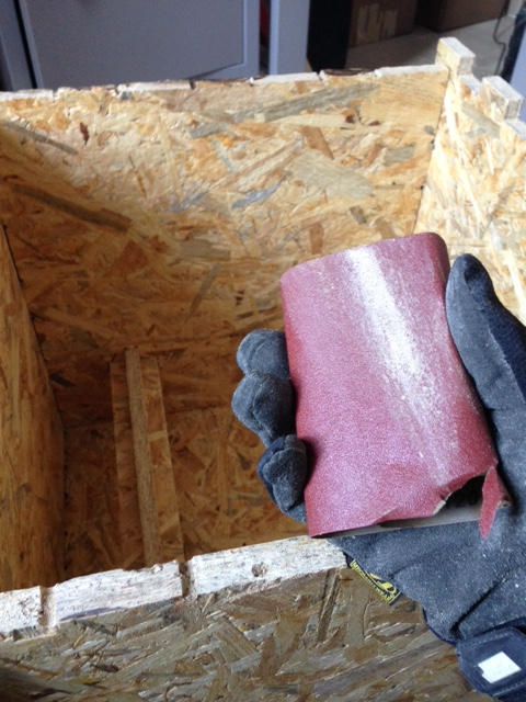
In this fairy tail you're the the Hunchback of Notre Dame and sandpaper, hammer, file, dremel and
hacksaw are your gargoyle friends.
I started little bu little to finish joint parts, some of
whose hadn't even been cut:
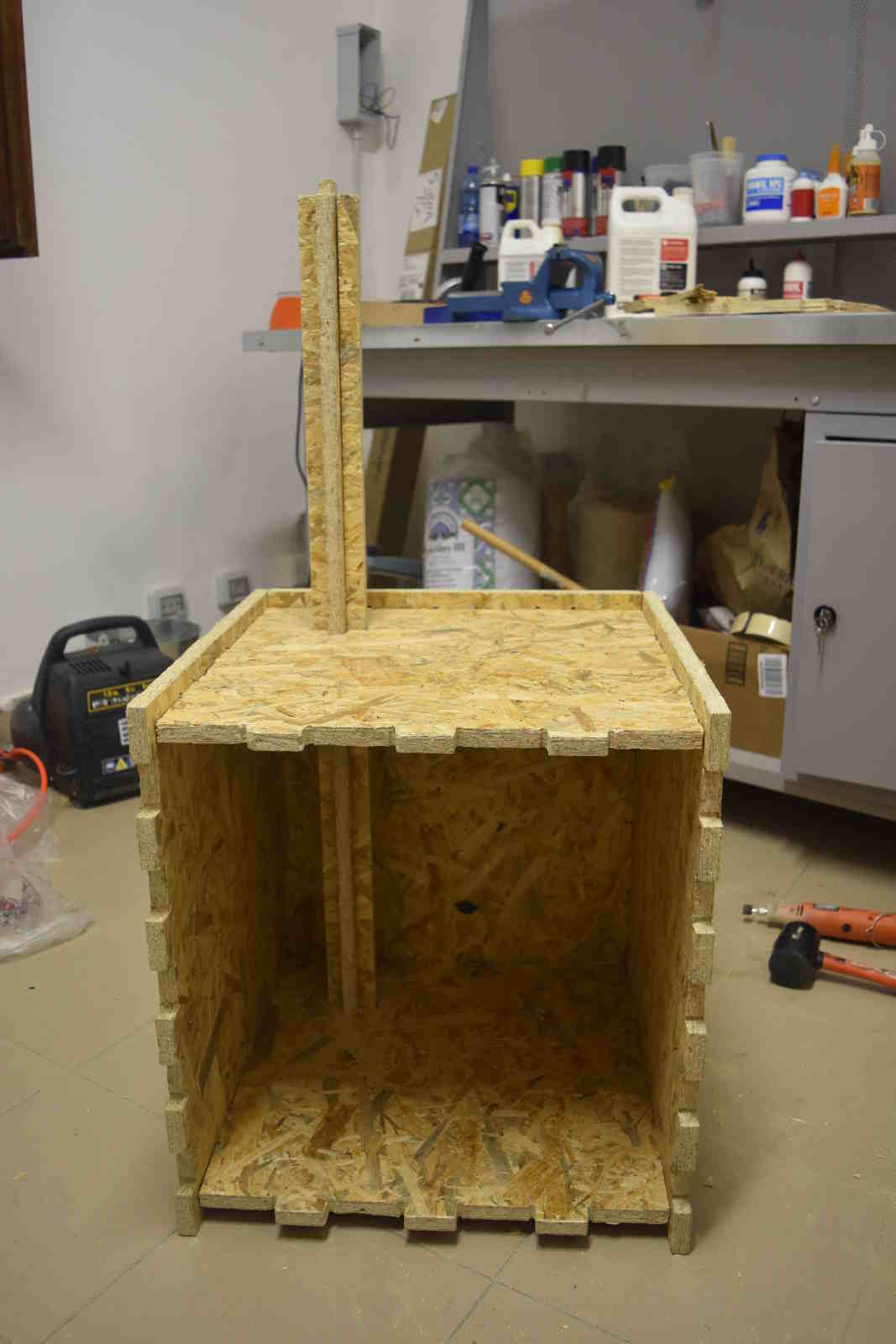 My judge Claude Frollo was the frontal panel:
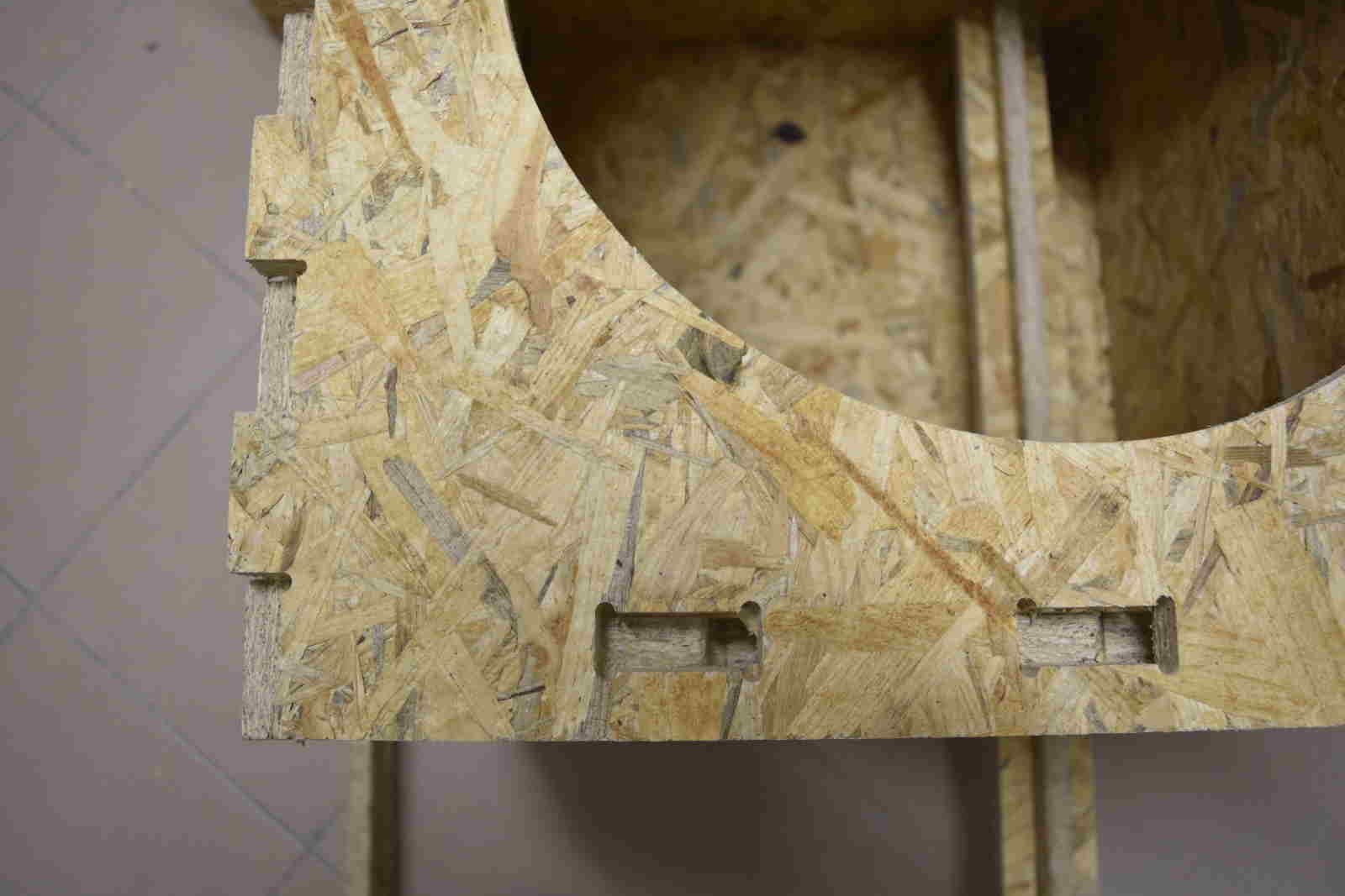
I had evident problems with joint alignment. I checked 3D file on Solidworks and it was ok so I had problems in the
.dxf exportation since, alreayd on Illustrator, joint holes appeared to be not aligned.
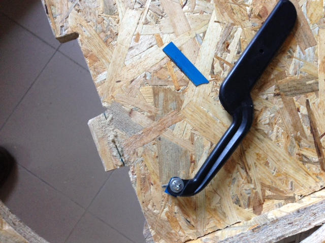
After breaking the hacksaw...
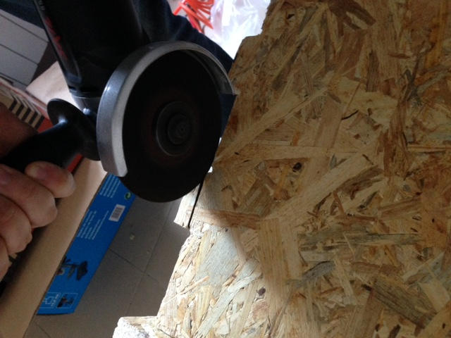
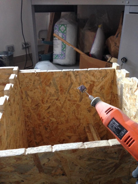
 ....I moved to grinder solution which revealed to be much faster and easier.
 Then with dremel and sandpaper I finished surface..
 ..and fixed the mistake :)
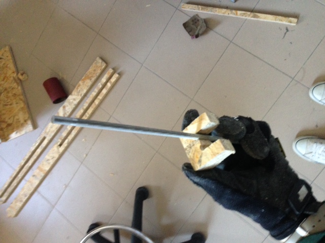
Moreover, I broke one of two longer pile in the attempt of matching them together and so I simply cut it another time
( cause I still hadn't realized I made another mistake).
This time it was harder to set working area sizes cause I had really little space (and so I payed four times more attention).
I repeated all the passages explained before.
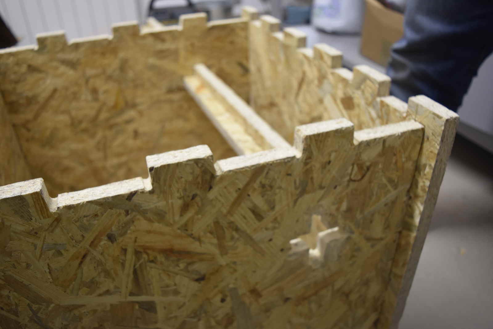
 Once I took out new pieces, I realized something didn't add up with pile joint:
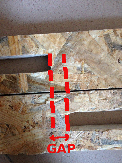 I immediately understood I made a mistake on Solidworks when making longer piles from shorter ones by increasing
external lenght but not inner joint one.
I immediately understood I made a mistake on Solidworks when making longer piles from shorter ones by increasing
external lenght but not inner joint one.
So, back down to work and sand hard.
TIP: file is your bestfriend with T-bones ;)
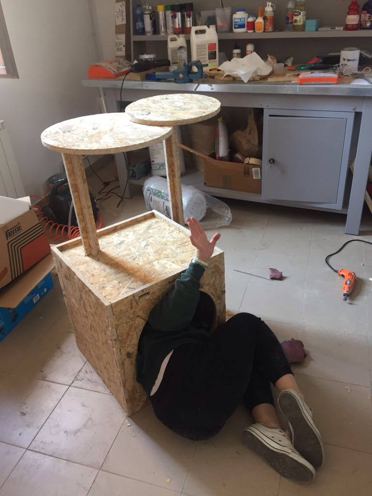
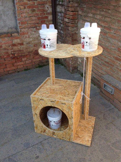 Those cats didn't purr when I placed them in their new house but I'm sure they'll appreciate more once I will cover piles
with rope and walls with colourful fabrics.
Those cats didn't purr when I placed them in their new house but I'm sure they'll appreciate more once I will cover piles
with rope and walls with colourful fabrics.
NB: the cord I tied to upper floor is intended to tighten a stuffed mouse and not for hanging cats.
Other interpretations
Human-friendly house
An awful interpretation
My funny friends suggest my scratcher could become a slaughterhouse for cats:
- Sacrificial altar: on the upper level the sacrificial victim (the cat) is shown to onlookers;
- Hanging: the cord I tied to upper level is perfect for cat hanging;
- Grave: the lowest level is where dead cat should be placed once dead
I know, they're really mean people.