Introduction
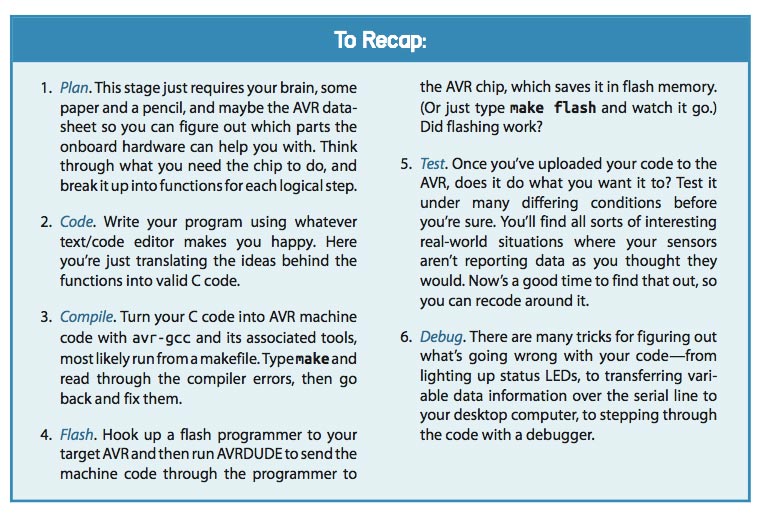
The assignments of this week were:- Read a microcontroller data sheet.
- Program your board to do something, with as many different programming languages and programming environments as possible.
- Optionally, experiment with other architectures
PROGRAMMING
I have never studied anything about this subject before, so I have found all this stuff extremely difficult. I didn’t know where to begin so my instructor suggested me to read Make: AVR programming If you are a totally beginner like me, it is the right book. It explained very well what a micro controller is, how it works and what are the main differences between the pins. First chapter is an overview of the chip and what it can do for you. This is a short list whit main concepts:- The AVR family of microcontrollers have 8-bit CPUs without a floating-point math coprocessor inside. This means that most of the math and computation you do will involve 8-bit or 16-bit numbers (this means that without it can't do decimal operations. Ex: 4/3 will give as result 1).
- Microcontroller does all this marvellous stuff by reading voltages applied to its various pins or by setting up output voltages to these very same pins.
- Microcontroller is a very small computer with 3 different memory:
- FLASH: nonvolatile memory which I uploaded my code and it doesn’t disappear when my chip loses power
- RAM: temporary memory for storing temporary variables
- EEPROM: like flash program memory, it stays around when the power goes out (honestly I didn't understand to much what this memory need).
- OUTPUTS: Almost all of the pins on the AVR chips can be configured so that they’re usable as digital outputs, meaning that the pin can be commanded in software to output either the supply voltage level or the ground voltage level.
- INPUTS: Just as almost all the pins can be set up as outputs, they can also be configured as digital inputs, where they detect if the voltage applied to the pin externally is high or low
- Other important things are interrupt service routine and internal counters.
Chapter 2 introduces me in the programming world. At this point all has become hard. A special thank goes to Simone Guercio who spend some of his time to explain me all about it. He explained each part of Toolchain and all became more clear.
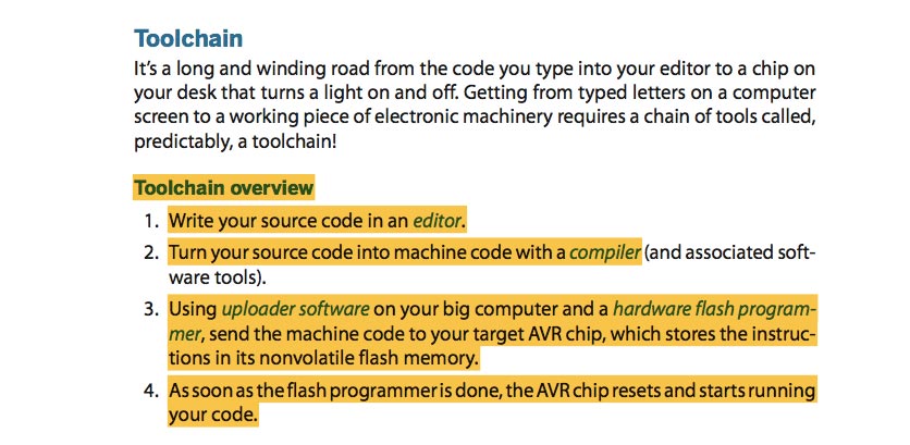
By using this Toolchain I'll show you my workflow:
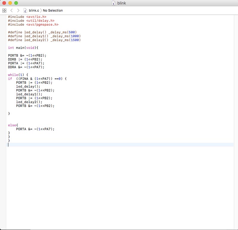
1) WRITE C CODE IN AN EDITOR
I have a MacBook, so as editor I have used TextEdit. I didn't know anything about C so I decided to use Flavio Lampus documentation as support. I read his blink sketch and then I have looking for some explanation on Internet.
#include command is used to add libraries you need. In this case I already had libraries that I need because I had installed during week 4 when I had to build my FabISP, otherwise you can downloaded it from Internet.
#define command is used to define constants. In this case I used define to set the led delay. I have setted 3 different delay to do some tests.
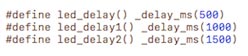
ms: it is the unity of measure and mean "microseconds".
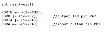
In this line I have set up which pin had to be output and which had to be input.
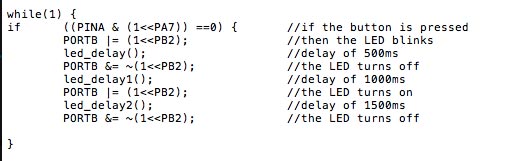
At this point I have define the routine with if and else command.
Each line means:
- PINB: is the register that gives you back PORTB and the initial value is 00000000.
- &: it is binary AND operator. Compare two 8-cells rows and if there are 1 in the same position in both line, value change as 00000100.
- (1 << PB2): Starting from right end, I set 1 in third position.
- |: it is binary OR operator.
- ~: it flipping bits. For example: 00100100=11011011.
If the button is pressed then the LED will blink, then turn off and blink again for a short period. If the button stay pressed, this command will start from the beginning. If the button is not pressed, then the LED will not turns on. I used some mathematical and logical operators and for understand what they was for, I read this tutorial. This is a screenshot of my sketch for my hello board.
2) TURN YOUR SOURCE CODE INTO MACHINE CODE WITH A COMPILER
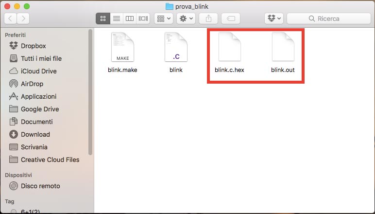
What means compiling? Means turning into machine language (binary code) a human-readable C code (my C file). For doing that I need AVR-GCC. It is a specific version of GCC-Compiler and a makefile. To be honest a makefile wasn't necessary in this case because for blink my LED I had only few command. I have tried to do it, so I downloaded Neil's hello-board makefile and I named it with my project. On the my desktop I created a new folder with .C file and .make file. Then I opened a terminal, I went in the folder and I ran this command:
make -f blink.makeThis is the result. I created .hex and .out files.
3) USING UPLOADER SOFTWARE AND HARDWARE FLASH PROGRAMMER
After created the new files, in the terminal I ran this two command for Flashing(means uploading the code from computer to microcontroller):
make -f blink.make program-usbtiny-fuses
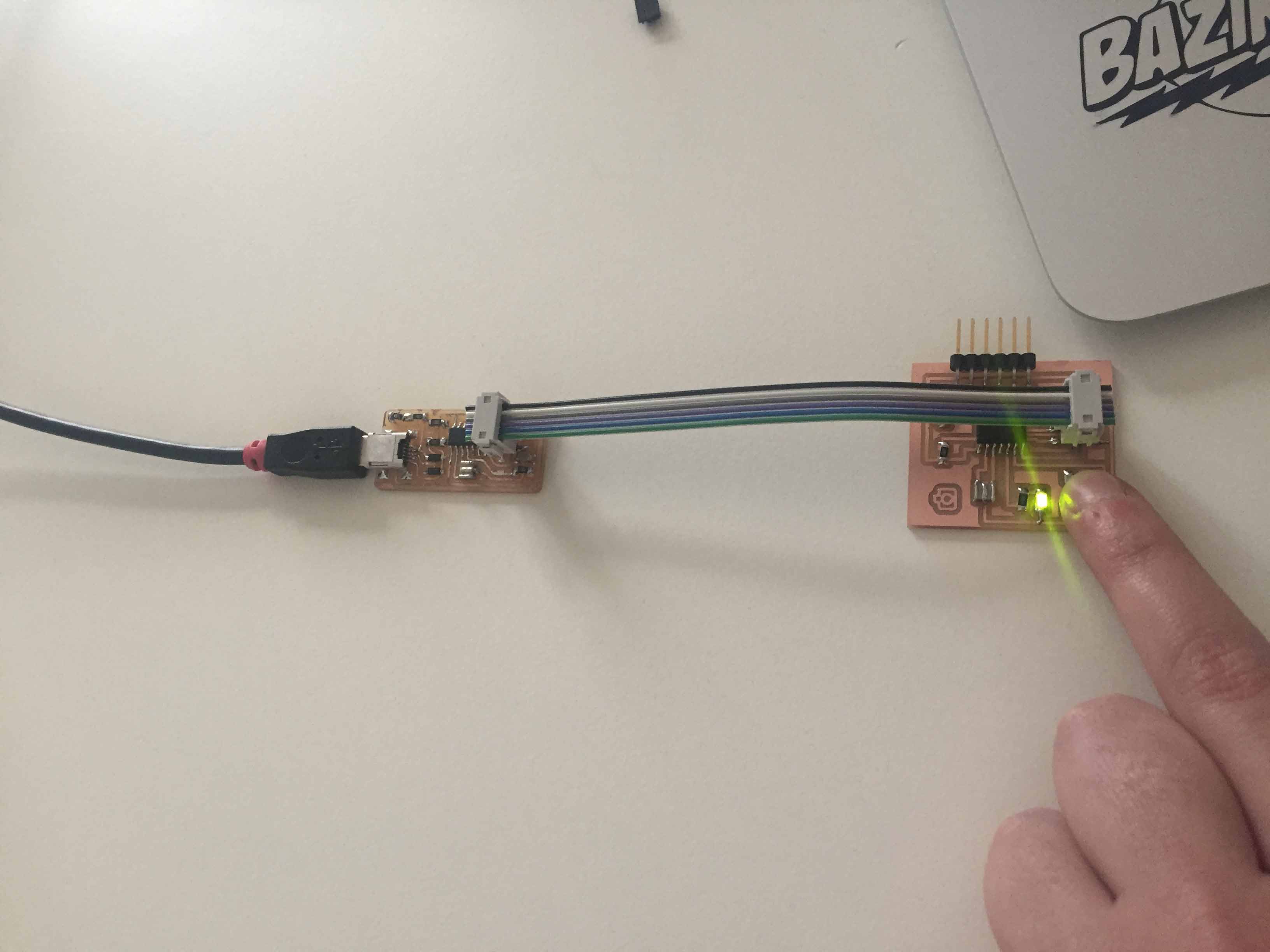
make -f blink.make program-usbtinyIt worked fine. My LED blink and my button works fine!
DATA SHEET
I had many difficult to understand the DataSheet. I tried to read it alone, but I needed help. So our instructor explained us some usefull things.
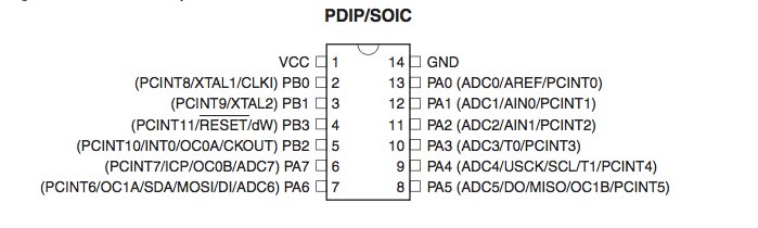
This is a schematic picture of my microcontroller, it was usefull to understand in which pins I have connected LED and Button.
The Button was connected to PA7.
The LED was connected to PB2.
So for understand how turn pins in digital ports, I needed the register of it. For the Button I reading this two register (DDRx and PINx).
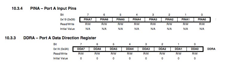
This is the register for PB2 (LED). It was an output so I had read this register (DDRx and PORTx).
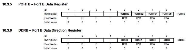
The difference between each registers is:
- DDRx: (Data Direction Register): this register check and decide if pin are set as input or output - by default pin are setted at 0.
- PORTx: (port data register): when DDRx is set as output(1), with PORTx register can set logic high or low (VCC or GND) for the pins considered.
- PINx: (port input pin address) they are where you read input pin values from (but you can also write in them)
This week was really hard for me, I don't understand a lot of things yet, but I want to keep on studing. I've tried to read Datasheet about other components and I've found it easily than this one. Of course, this is a microcontroller datasheet, not a components datasheet, so it's normal that it is complicated. I have found a lot of things that I don't understand, for example, how read block diagram. Why it is useful?
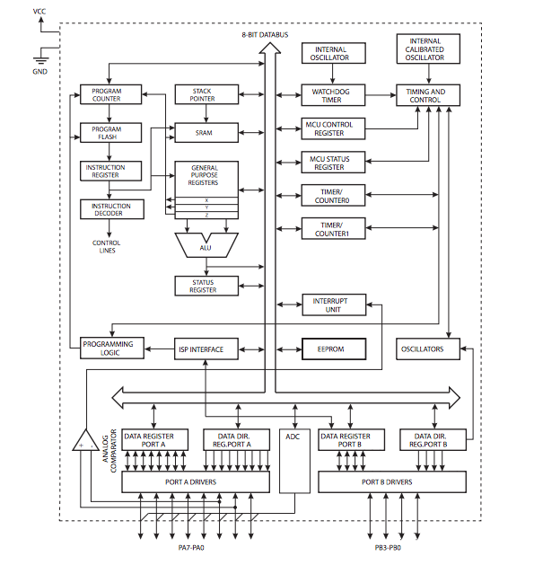
I have looking for some help in the other documentation from Fab Academy students, I thought "for sure someone else had the same problem!". I have found some answer on documentation of my dear friend Silvia. She have understand more than me how read this diagram, so I use her page to study. It explain logical connection between each function, where the I/O function happens, and the differences between PORT A and PORT B. With this diagram I understood that PORT A have an Analog/Digital convertor capability and PORT B doesn't. Another useful documetation is Shelga's page. It is usefull expecially to understand what means each name on the pinout. For example on Isp connector I have pins like MOSI and MISO, but what is their function? what this name means?
MISO (Master Input Slave Output) and MOSI (Master Output Slave Input) are usefull for the networking communication, to exchange data.
ADC (Analog Digital Converter): If you read the pinout, beside some pins I found this symbol. It show me which pin can be used as Analog or Digital pins.
XTAL (cristal input): When you need to add an external crystal you must connect it at this pin. You found the right position reading the microcontroller pinout.
I have also checked out which pin could do what. Some microcontroller pins have a specific function, so I must pay attention at this when I draw a board. In the datasheet I found a table who explain this:
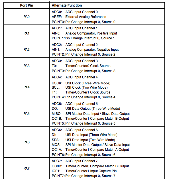
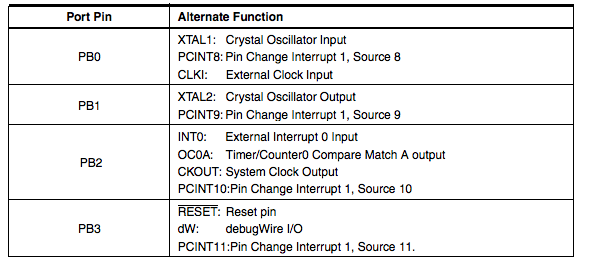
As a beginner, was very difficult to read the doc. Many acronyms, very technical terms! I think that what is important to understand is that the complete documentation is the reference guide for how to use the microcontroller. 90% of the information brings answers to questions we may have while using the microcontroller, not before using it.
ARDUINO IDE
This is an update about my programming works. During Output Device, Input Device, Networking, Interface and for my Final Project, I have used the Arduino IDE as development environment. Arduino languages is developed on C languages, but it is easier than C. Even those who haven't program before, can learn it easily and quickly. To understand how it works, I read the main function and some example on the Arduino site. In this page I have leared how connect my board and how upload some sketch.
During this week, I have used Arduino board for some tests, but mainly I have use Arduino environmental to wrote some sketch for the board that I have milled.
Basically upload a sketch is easy but there are some difference if you used a different microcontroller or a different programmer.
When you have wrote your code, selecting menu Tools -> Board you must select the right microcontoller. In my case I have selected AtTiny 44 because I have soldered it on my boards.
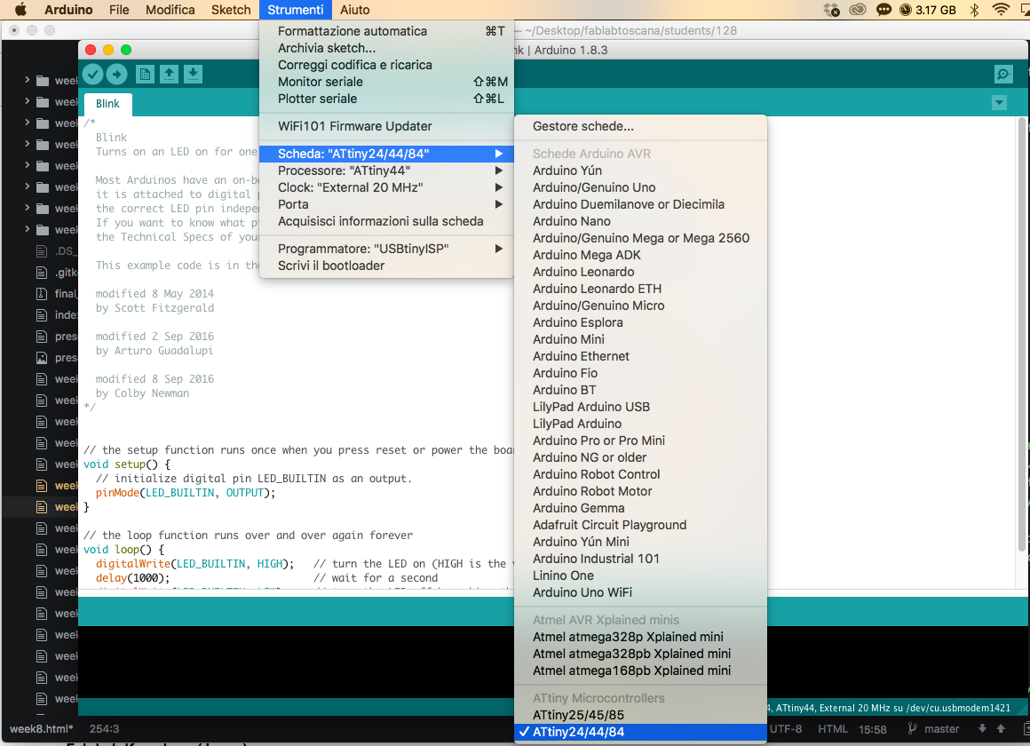
Second step was selected the right microcontroller. As you can see in Board menu, you select AtTiny 24/44/84. They are three different microcontroller with the same characteristic except flash, RAM and EEPROM memory.
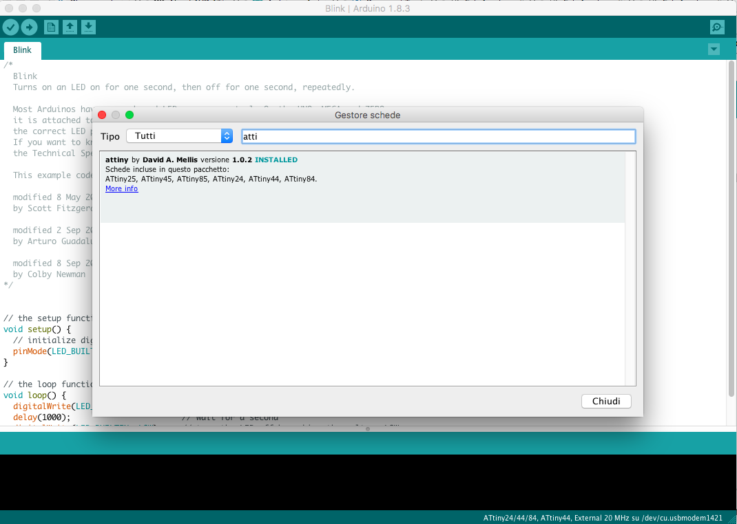
ATTENTION!!: to install AtTiny library, in Tools -> Board -> Boards Manager, search AtTiny 24/44/84 and the install it.
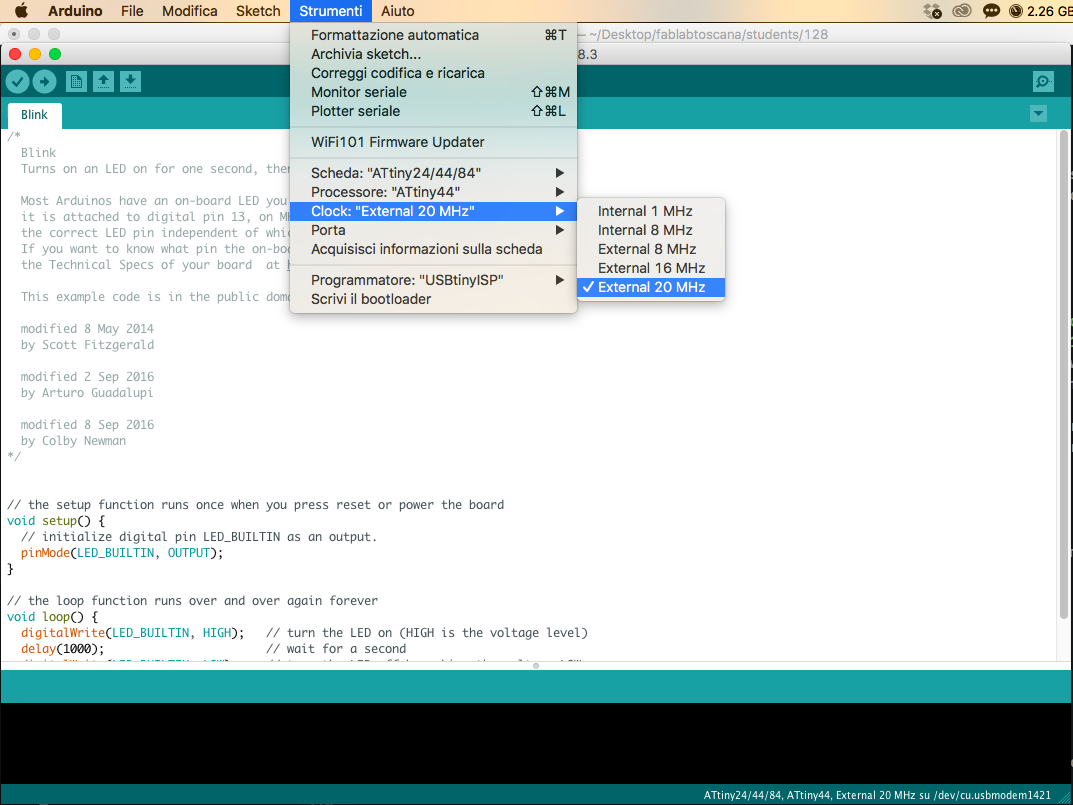
Third step was selected the Clock. To upload an Arduino sketch on AtTiny44 I need to use an external clock, because the internal one wasn't enough, so on my board I have soldered a 20MHz Xtal. I have selected it always in Tools menu.
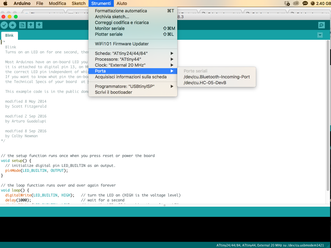
Fourth step was selected the right Port. If I connected board at my pc, opening Port menu I get a list where I can choose the right one.
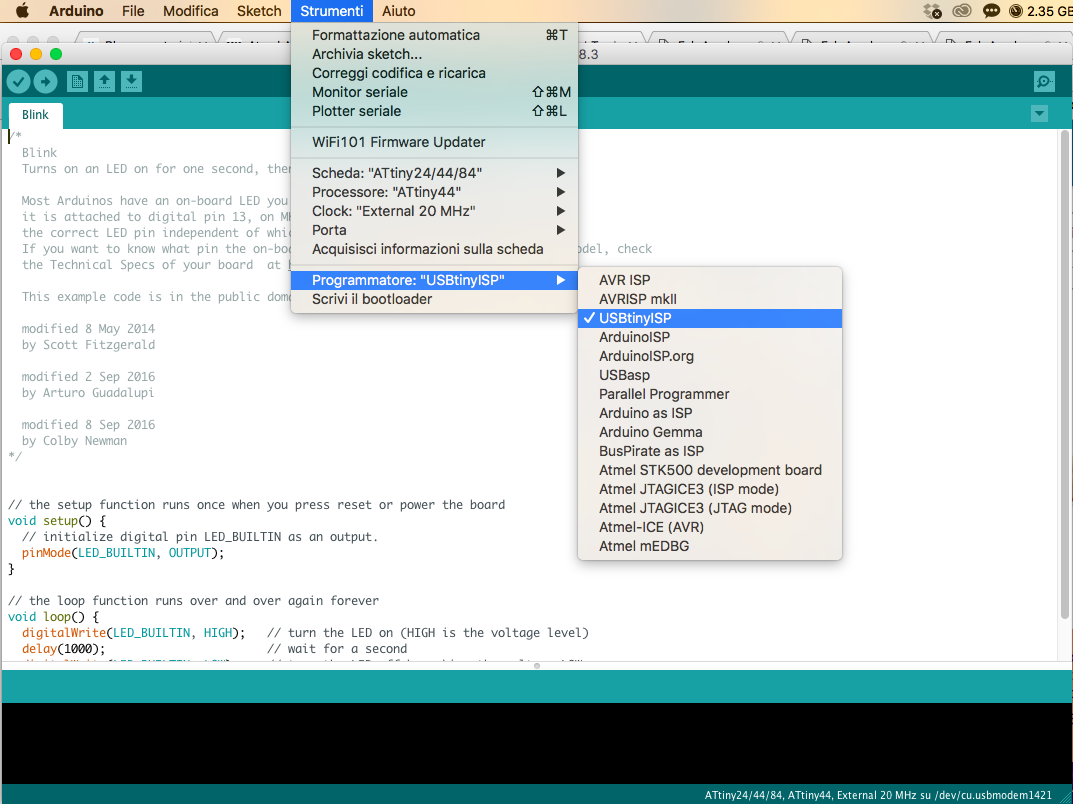
Fifth step was selected the programmer. If I use my FabISP as programmer I need to select it otherwise I can't upload my sketch. It use Arduino as default.
Last step was upload the sketch. When I use my FabISP I can't use the Upload button, but I have to used menu Sketch -> Upload with a programmer
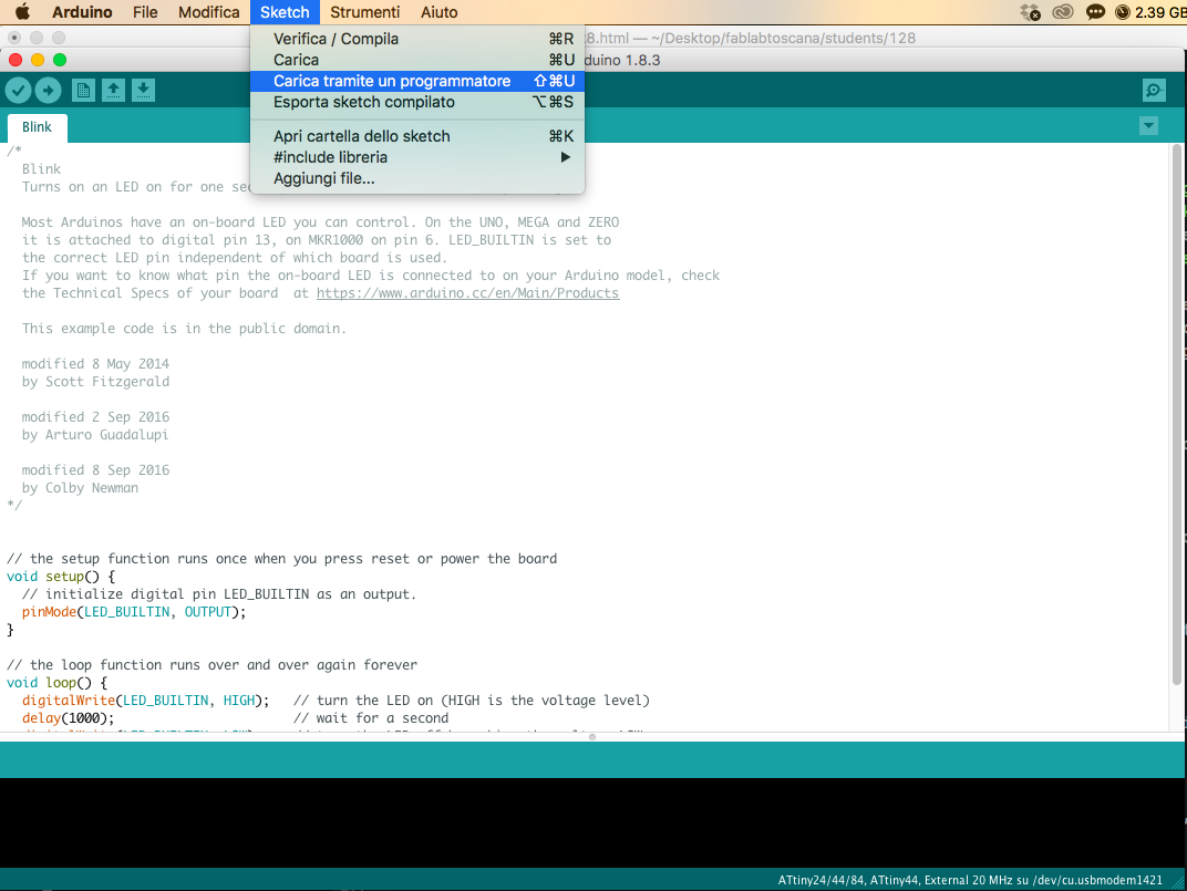
If sketch is correct you have upload it with success.
CONCLUSION AND DOWNLOAD
This week was really hard for me. C languages is a mistery, but I hope to take more confidence with it, I hope to improve my skills.
You can download my files here.

This work is licensed under aCreative Commons Attribution - ShareAlike 4.0 International License.