Introduction
The assignment of this week was:- Design and build a wired &/or wireless network connecting at least two processors
THEORY: AVR PROGRAMMING AND OTHER TUTORIAL
Ok, this week wasn't easy for me. I thought that the best thing that I could do was read something about it.
I decided to read chapter 17 of Make: AVR programming cause it explain clearly what I2C is.
The most important things to know are:
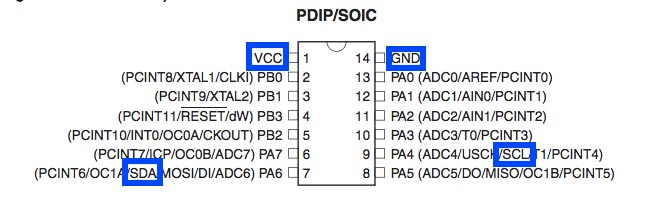
- I2C it's a serial protocol for networking communication who use two pins (in addition to GND and VCC pins):
- SDA for "serial data".
- SCL for "serial clock", it is always generate by the current bus master.
- It is SYNCHRONOUS protocol, so there is a clock master who controls the communication by sending out the timing signal.
- It is FULL-DUPLEX, which means that both device can send and receive data at the same time.
- Each device have a 7 bits address and every communication between master and slave begin with it. The 8th bit is reserved for write/read direction:
- ONE - HIGH LEVEL: master read data
- ZERO - LOW LEVEL: master write data
- There is a 9th bit who recognize the received bytes:
- ACK: zero or low means that the byte is acknowledged and the slave device should continue sending.
- NACK: one or high means that there is an error and transmission ends.
- With I2C you can connect up to 128 devices.
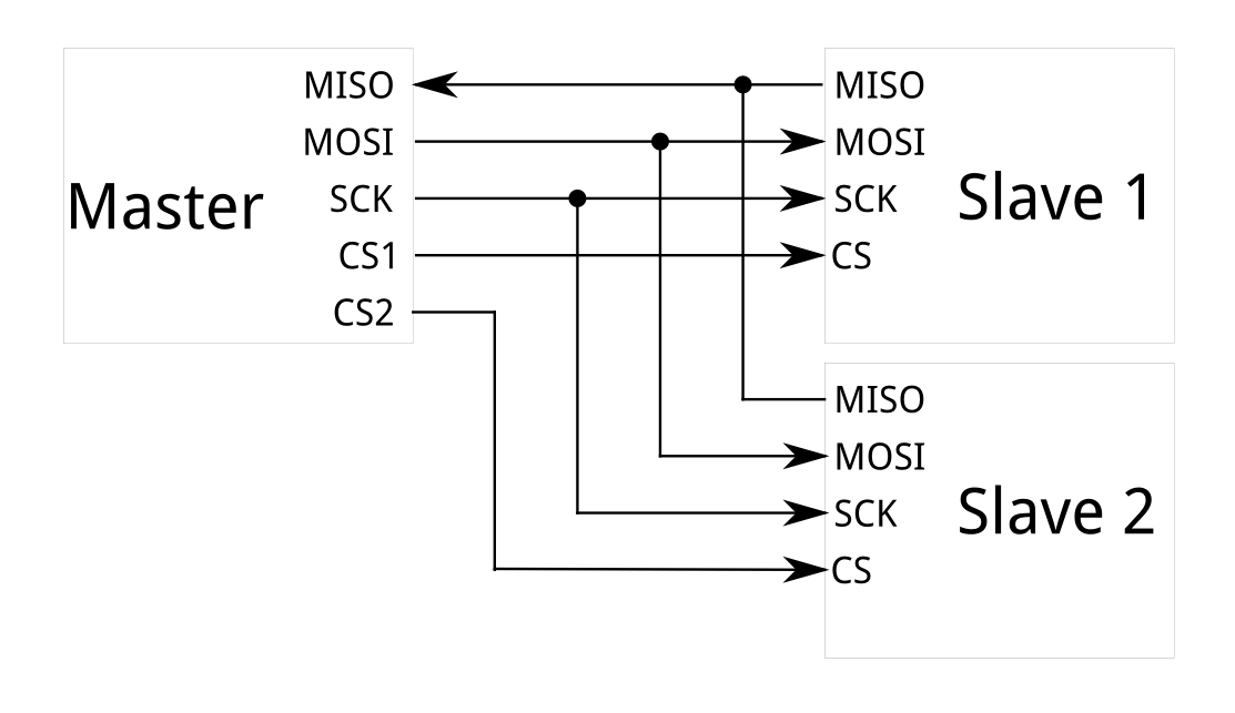
With SPI I need four pin to connect a Master with one Slave, so if I have 2 or 3 Slave board the situation became a mess. Furthermore with all this wires, the communication will be more difficulties.
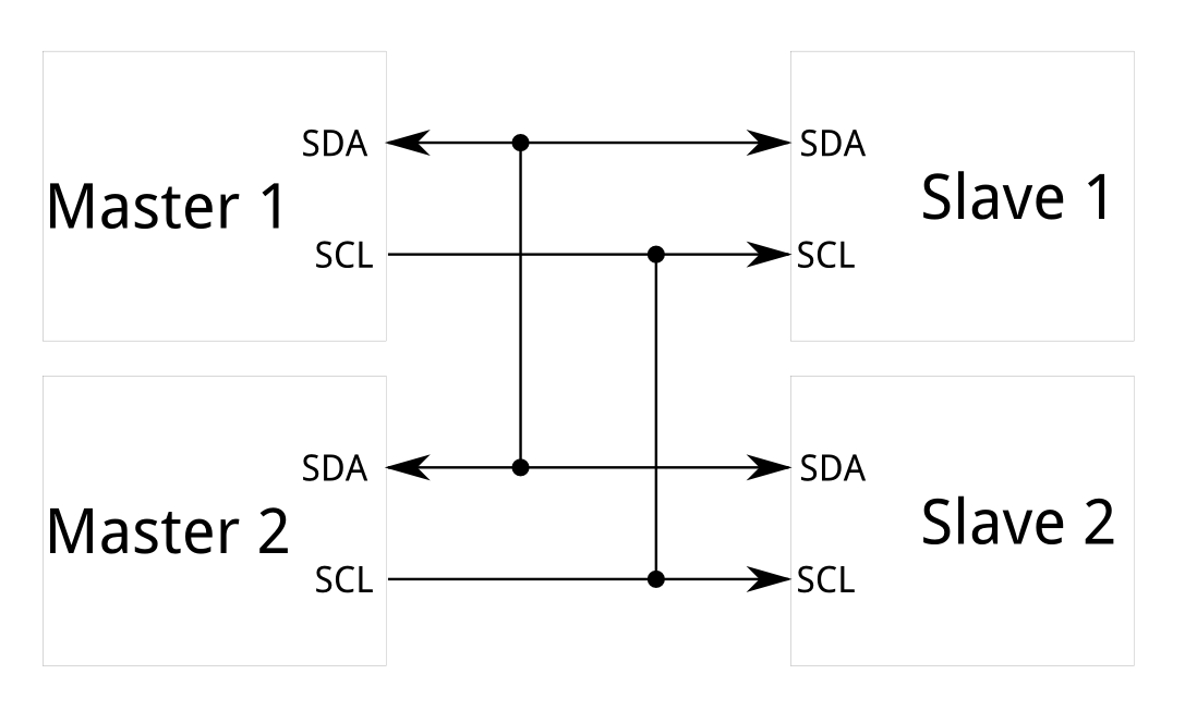
The I2C communication, as you can see in the picture above, required less wires to work. Also, it can support a multi-master system.
WIRE AND TINYWIRE LIBRARY
To write the code I need to download two library: Wire and Tinywire (S for the Slave, M for the Master). What is the difference?
Wire works on ATmega328 (Arduino's microcontroller) and not on ATtiny44/45. Tinywire is the same as Wire, but it works on ATtiny 44/45.
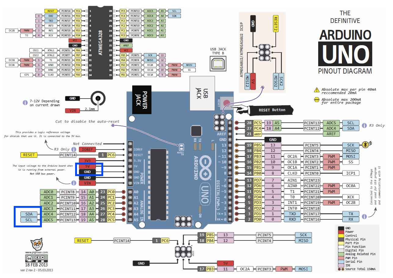
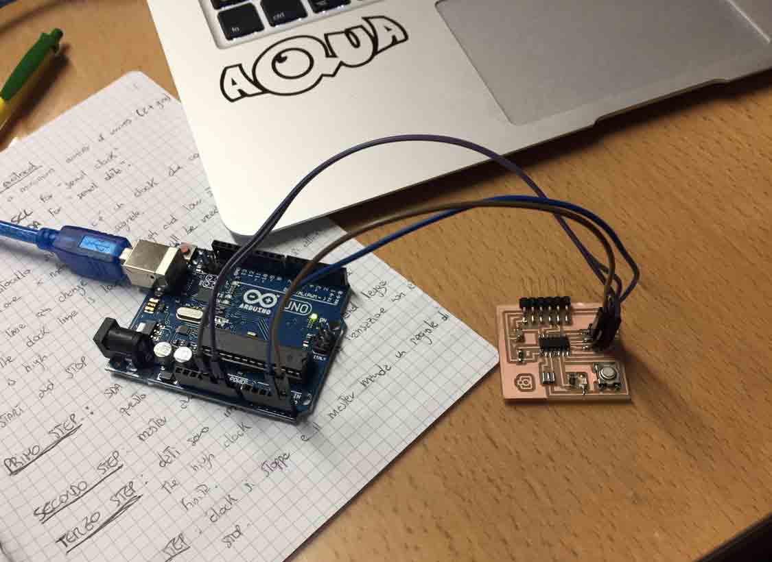
On Wire library documentation (link) I have found the description about each command. After that I tried to understand how connect my board (helloboard from week 6 assignment) at Arduino that I used as master device. First of all I have looking on internet the Arduino's pinout to understand where are SDA and SCL pins.
Then I've checked on ATtiny44 datasheet to see the pinout.
I have connected it at my computer and I move on Arduino IDE to write the code.
CODE
Thanks to Simone helps, I wrote my code. This is the code for master
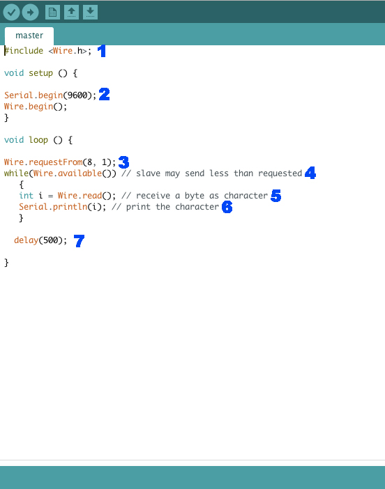
1) I have include Wire library.
2) In setup I have setted the serial boundrate as 9600bps (byte-per-second), and with Wire.begin() I have initiated the Wire library for Master device.
3) This command is to request bytes from a slave device. First value is the slave address and the second is the number of bytes that I requested.
4) With this command checked if some bytes are available for reading.
5) Wire.read read the value on SDA.
6) This command is to print the character on serial monitor.
7) This function will repeat each 500ms.
This is the code for slave
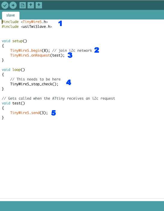
1) I have include TinyWireS library because I will use my helloboard as slave.
2) I have set Wire.begin(8). 8 is the slave address.
3) This function register a function to be call when master request some data from a slave device. In this case the function 'test'.
4) As you can see in the comment on the screenshot, this line needs to be there.
5) Set what I will see on serial monitor.
After that I have uploaded master code on Arduino and slave code on my helloboard.
This video show how it works.
BLUETOOTH
I decided to try to use Bluetooth module expecially because I will to use it for my final project. I have looking for some tutorial on internet and I have found some usefull links. I have linked it in the left menu.
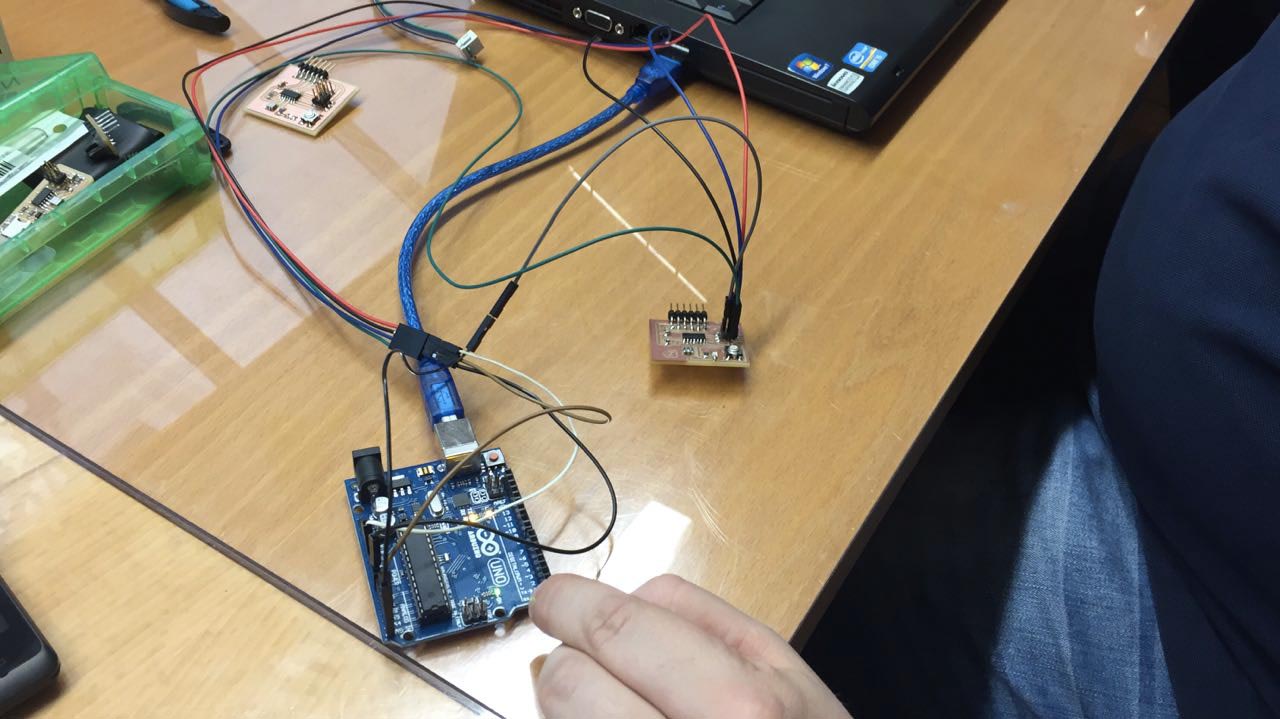
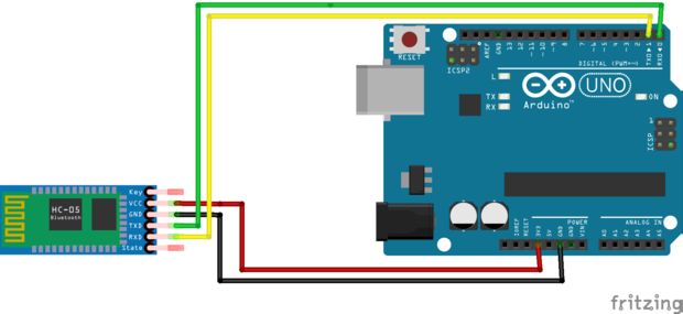
First of all I have configurated the HC-05 Bluetooth module. To do that I've connected it at Arduino with four wires: one at VCC (5V), GND, and in other two pins. I haven't used serial pin on Arduino but other two random pins that I have configurated thanks SoftwareSerial.h library.
ATTENTION!!!: Remeber to connect RX to TX and TX to RX to have a data exchange.
After connecting it I have reset it. How? Following this steps:
- press Bluetooth module button
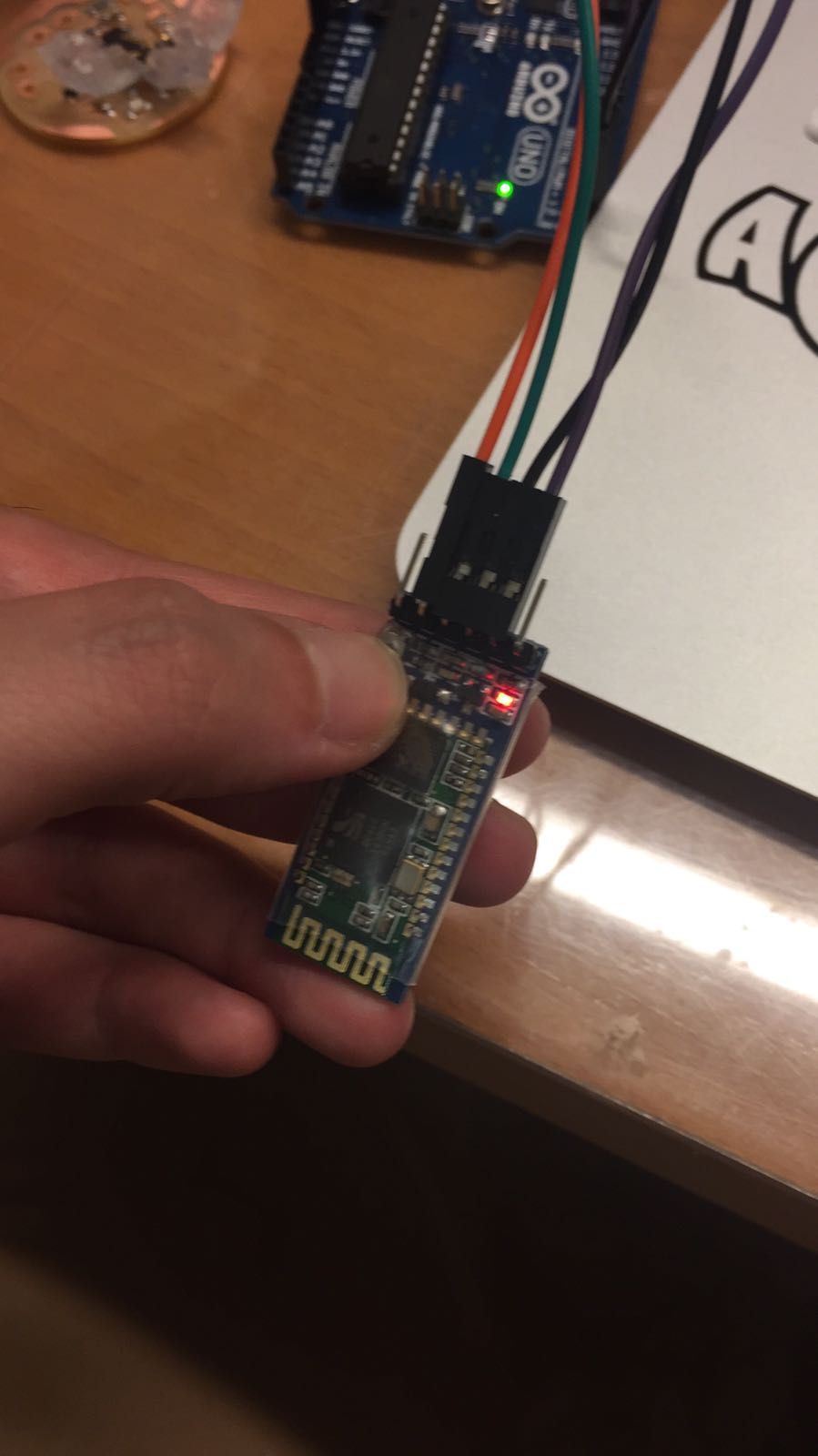
- while pressing the Bluetooth button, disconnect and reconnect Arduino from the computer
- at least leave the button from Bluetooth module.
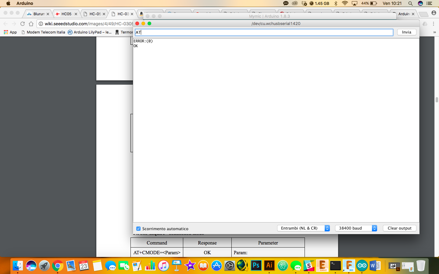
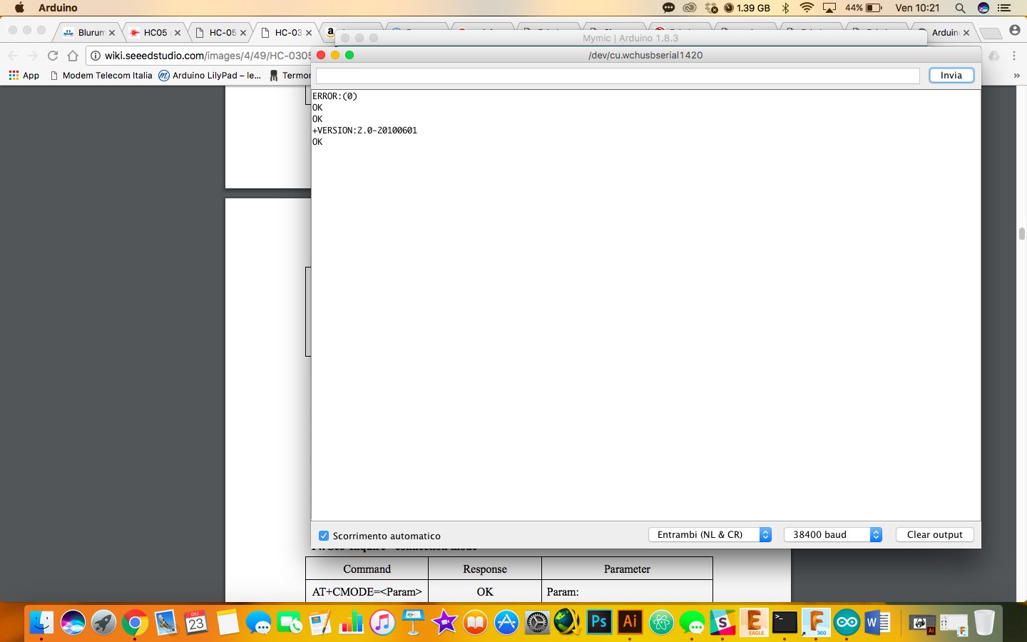
At this point I have opened serial monitor to see if I can communicate with the module to setting it.
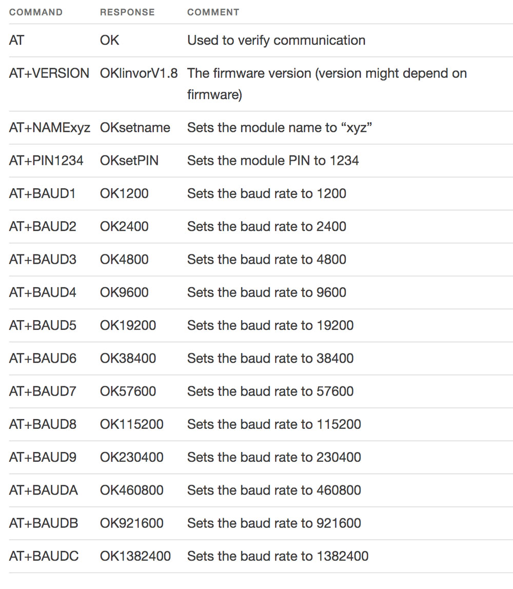
There some command that I can send to test it. The first one is AT. Sending this command, if I receive OK, it means that I can communicate with the module.
Then I have interrogated again my module sending this code AT+VERSION to see which firmware was installed on it.
There are a lot of command that I can send to it, each has a purpose.
I've sent command AT+UART? also, to see which is the default bandrate on this module. As I see on serial monitor it is at 9600. At this point I have connected module at my final project board. I have wrote a sketch on Arduino IDE on which if I press a button on serial monitor I should to see an answer. This is my code:
#include <SoftwareSerial.h> //Include library for the management of the instructions of use of the form bluetooth

const int rxpin = 2;  //Set at pin 2 address to receive data (connect it at TX pin on Bluetooth module)
const int txpin = 1;  //Set at pin 3 address to transmit data (connect it at RX pin on Bluetooth module)
SoftwareSerial bluetooth = SoftwareSerial(rxpin, txpin);  //Set a name at Bluetooth,  and his receiving  and  transmitting pin.


int ledPin = 7; // choose the pin for the LED
int motPin = 8; //motor pin
int vePin = A0;   // choose the input pin (for a pushbutton)
int val = 0;     // variable for reading the pin status

void setup() {

  bluetooth.begin(38400);  //Set baund rate value refering to AT
  pinMode(motPin, OUTPUT);  // declare motor as output
  pinMode(ledPin, OUTPUT);  // declare LED as output
  pinMode(vePin, INPUT);    // declare pushbutton as input
}

void loop(){

  val = analogRead(vePin);  // read input value
  if (val > 60) {         // check if the input is HIGH (button released)
    digitalWrite(motPin, HIGH);  // turn motor OFF
    bluetooth.write(1);  //Data will be send to bluetooth for the transmission.
  } else {
    digitalWrite(motPin, LOW);  // turn motor ON

  }
}
On the serial monitor I had to set the baund rate at 38400 because with 9600 I haven't any answer. I have looking on Internet why this happens, why if I asked at the module which is the baund rate it send me a value and then it doesn't work?
On different pages I have found always the same answers: default baund rate is 38400.
At this point I receive an answer but it isn't the right one. I couldn't find the problem yet, but I'm still working on it.
DOWNLOAD
You can find all files here

This work is licensed under aCreative Commons Attribution - ShareAlike 4.0 International License.