Final Projcet :
Exchange Eyes - The beauty and sorrow of the island
The finished final project presentation vedio is showed as follow:
::Introduction::
Orchid Island, located at southeast of Taiwan. Because the island had volcanic activity before, it had many particular terrain. People who live on the island was called TAO. They have quite a special tradition and culture. But also because of the beautiful scenery and unique cultural characteristics, many tourists are attracted to visit here.


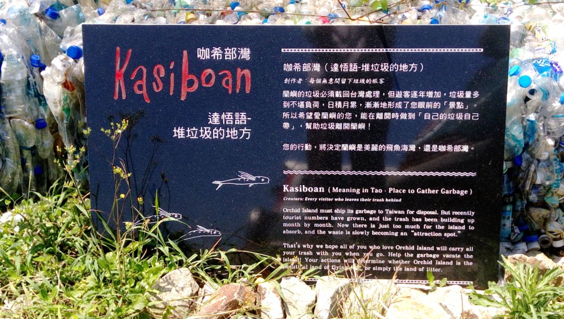
For a long time, they faced a very serious problem that they could not handle the garbage that came with the tourists. The rubbish needs to be returned to Taiwan, but the shipping costs are so high that they can not afford it.
There a man who is called Wen, he grew up in this island and found the problem. He built a new attraction called Kasiboan, but in fact, this place was where the rubbish be stacked. His purpose was to hope that visitors would see the place and then reflect on their destruction of the environment and then brought their garbage back to Taiwan.
I read about his report and tried to help him. I contacted with him and we discussed how to do. So my final project became.
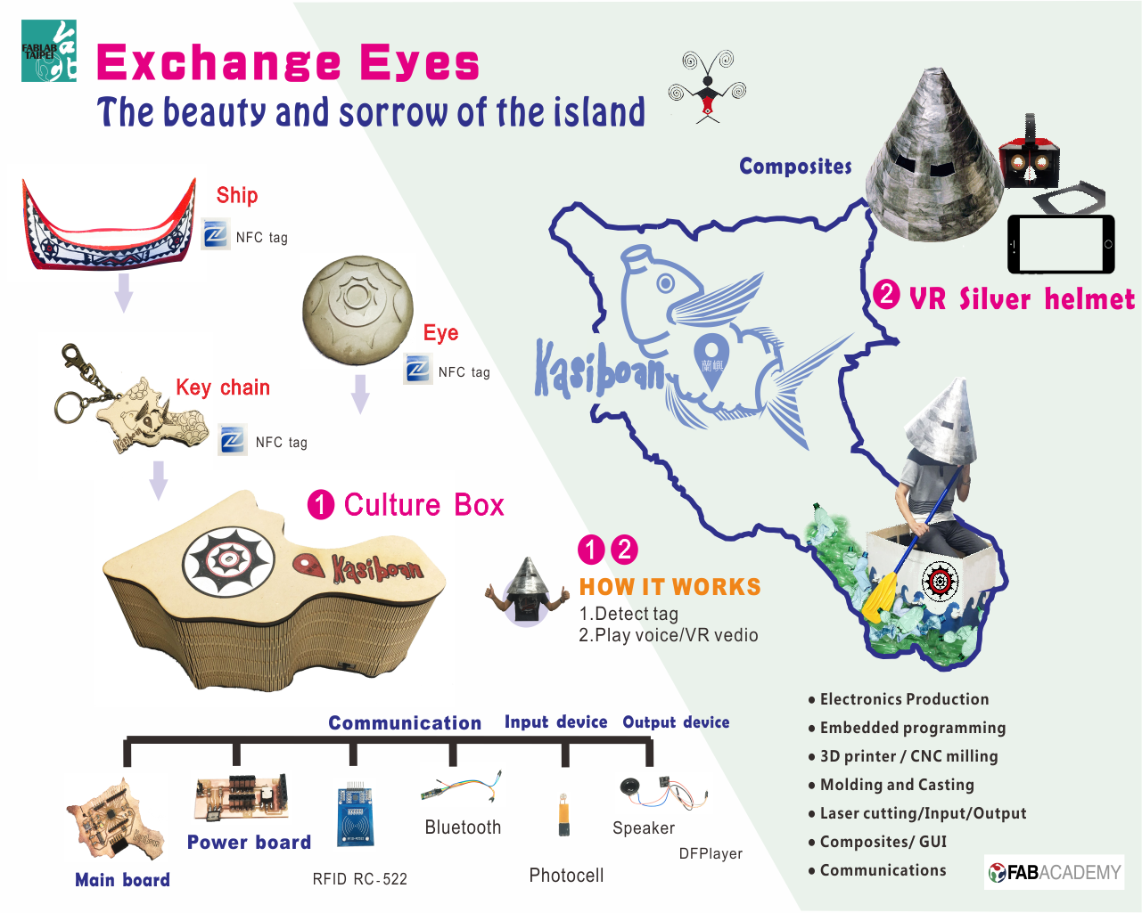
I want to make a culture box, which function is reading the tag message from the specific object with NFC(Near Field communication) technology. Then the culture box will plays a unique music/voice about the object.
Silver helmet is a unique helmet of TAO, and they would only wear this helmet on blessings or welcome ceremonies. I will also copy a silver helmet with a VR(Virtual Reality) glasses in it. Than I will capture a VR vedio about Kasiboan. Who finally wears the silver helmet and puts the specific object on the culture box. It will sends a message via bluetooth or wifi to the carboard to play the VR vedio.
What I want to do is exchanging the view of things. Once we are visitors,what we focus on is only scenery. While we wear the silver helmet, and look out from the helmet. It seems we become TAO, who live in here, and what we see is only garbage. So through my culture box, I hope we can reflect on the destruction of the environment, thereby reducing the manufacture of garbage.
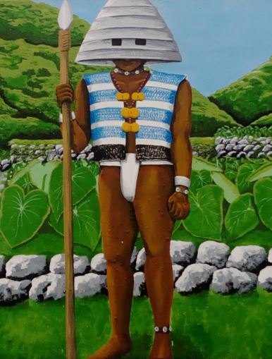
figure 1 : TAO.

figure 2 : Concept of final project.
::Culture Box -- Components::
The culture box includes lots of comaonents, such as objects, box, silver helmet and VR glasses.
The skills I used to build this box are electronics design, embedded programming, 3D printing, Laser cutting, input and output devices, molding and casting, composites, networking and communciations, interface and application programming.
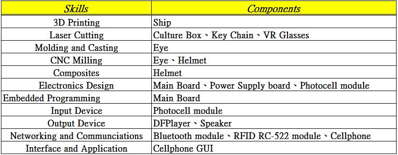
figure 3 : Sheet of skills I used in final project.
● Objects
I build three objects for my final project, which are ship, eye and key chain.
-- Ship ---
This puzzle boat is quite unique and important to TAO. There are quite a few beautiful totems on boat, representing different special meanings.
First, I draw the boat with Rhino, and use 3D printer to print this boat. Then I painted the boat to make it look like real. Finially, I stick a NFC (Near-field communication) tag on the back of the boat. The NFC tag has it's unique UID (unique ID) code which will be used to identify the boat at the following phases.

figure 4 : Draw boat with Rhino.
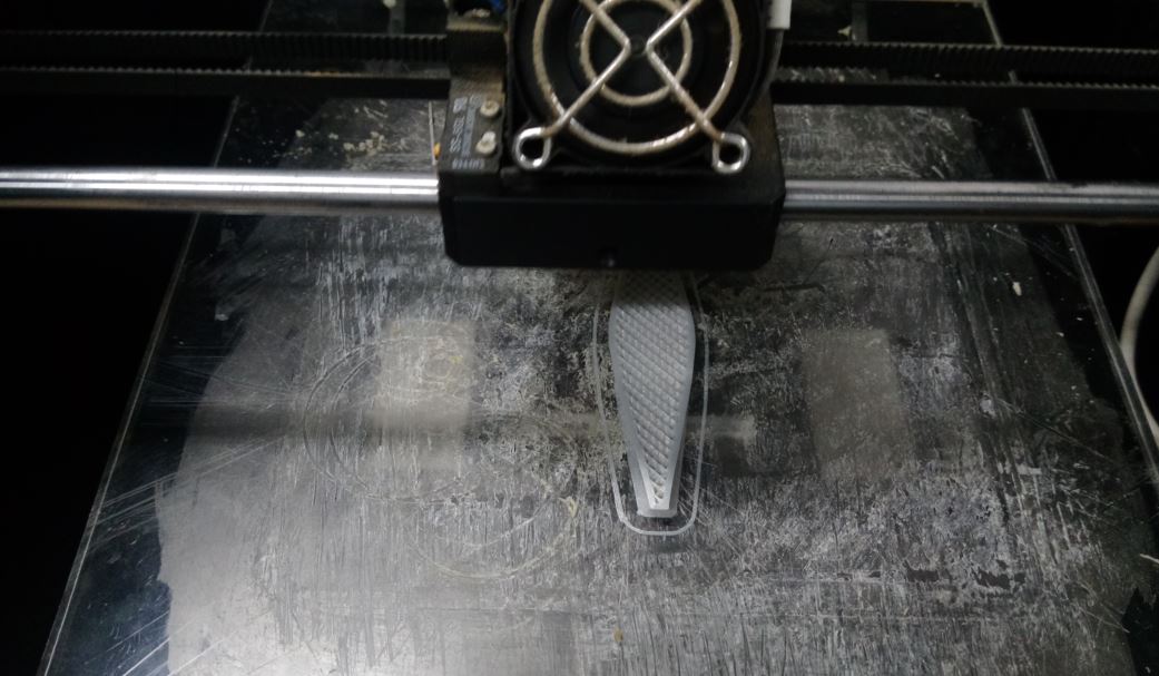
figure 5 : 3D printing the boat.
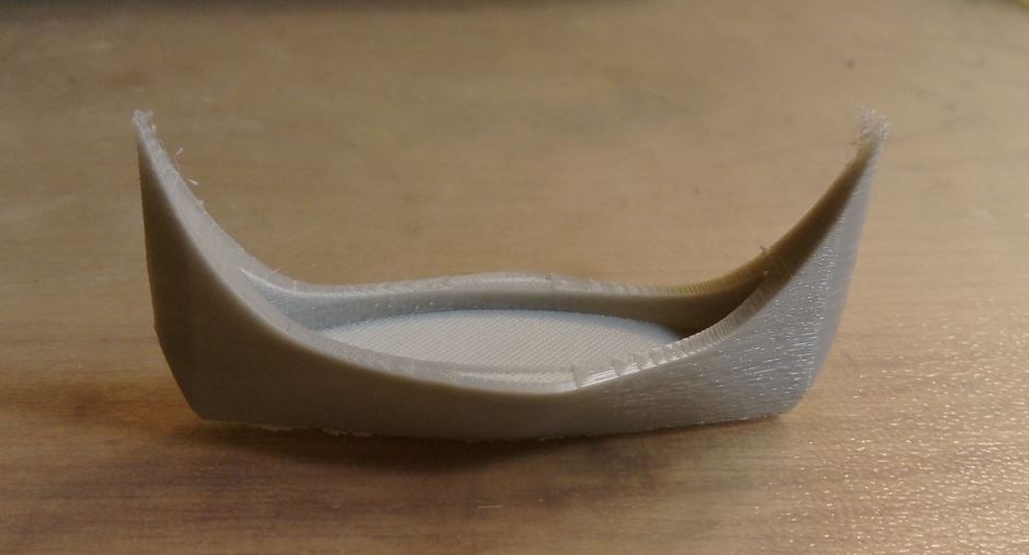
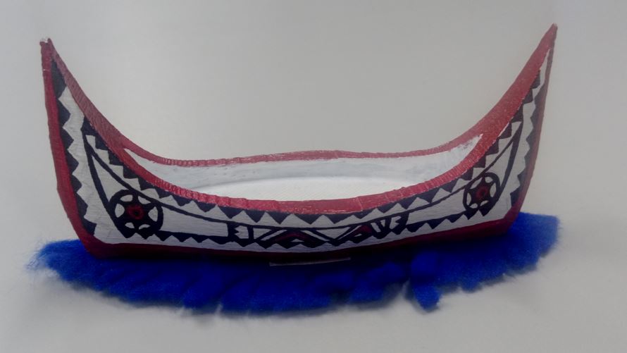
figure 6 : 3D printed boat.
-- Eye ---
The eyes of the ship, referring to when TAO fishing on the sea, eyes will guide the direction and to avoid disaster. It's a very important spiritual symbol of TAO.
I use molding and casting skills to build the eye. First, I draw the eye mold model with Fusion360. Second, I milling the positive mold via CNC machine. Third, I use oomoo to make the negative mold. Finially, I use resin fortified tile gripper to cast the eye.
After casting the eye, I also stick a NFC tag on the back of the eye for the following identify phase.
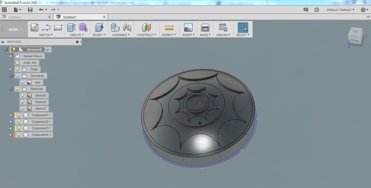
figure 7 : Draw eye with Fusion360.
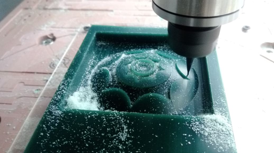
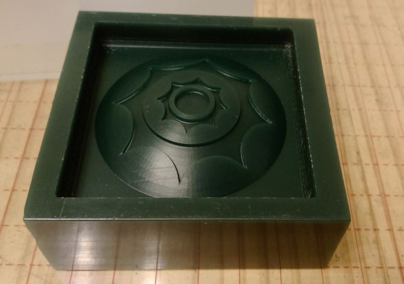
figure 8 : CNC milling the positive mold.
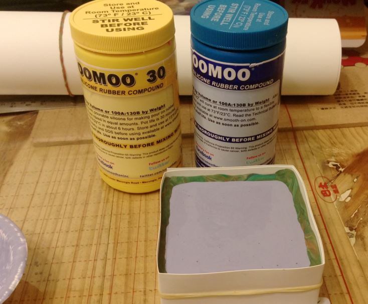
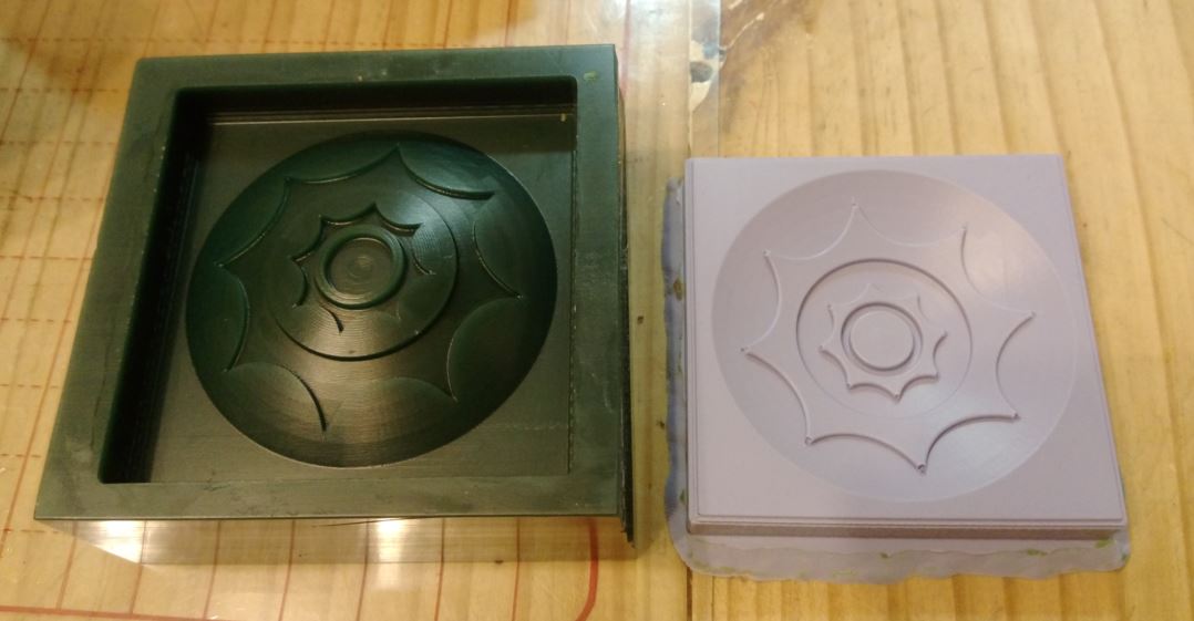
figure 9 : Use oomoo to build the negative mold.
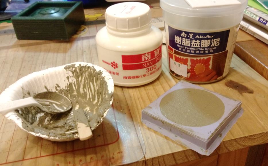
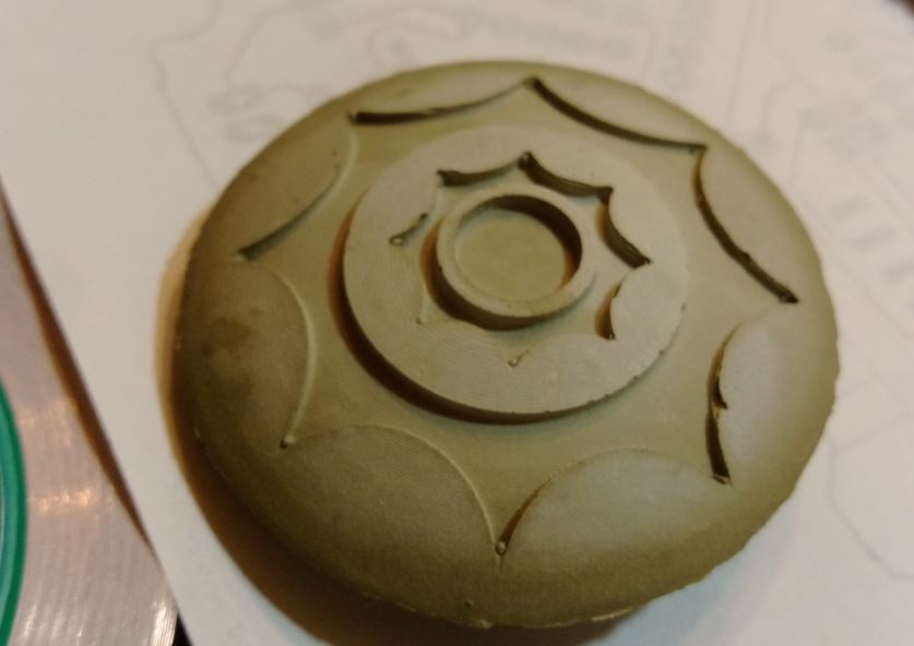
figure 10 : Casting the positive eye with resin fortified tile gripper .
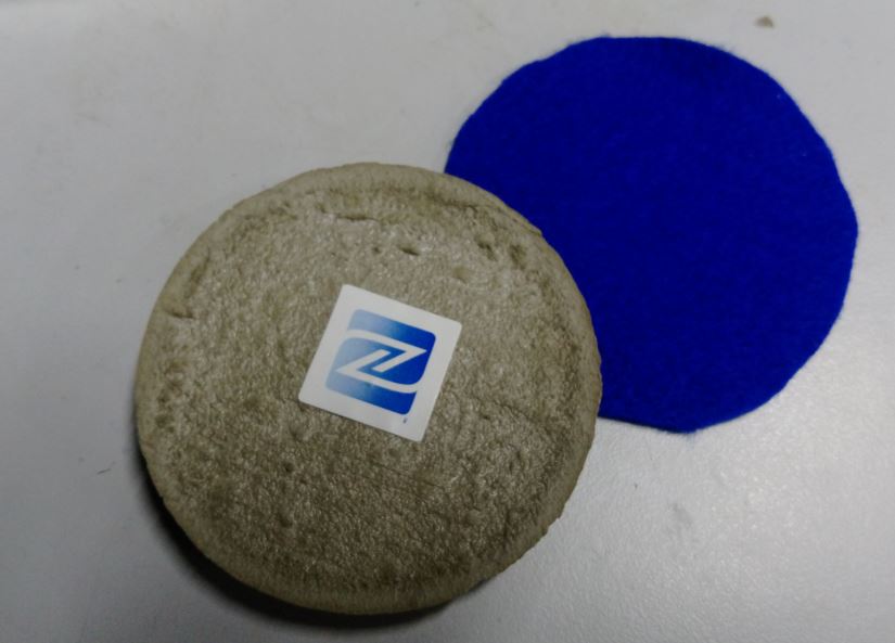
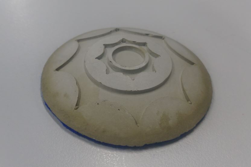
figure 11 : Stick a NFC on the back of the eye for following identify phase.
-- Key Chain ---
The third object, key chain, has a special maening, it represents Kasiboan which the place gathering garbage. First, I draw the key chain with 2D drawing software CorelDraw. Second, I choose pigskin and wood as the materials to be cut by laser cutter. Third, I also stick a NFC tag on the back of the eye for the following identify phase.

figure 12 : Draw key chain with CorelDraw.
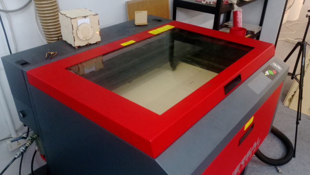
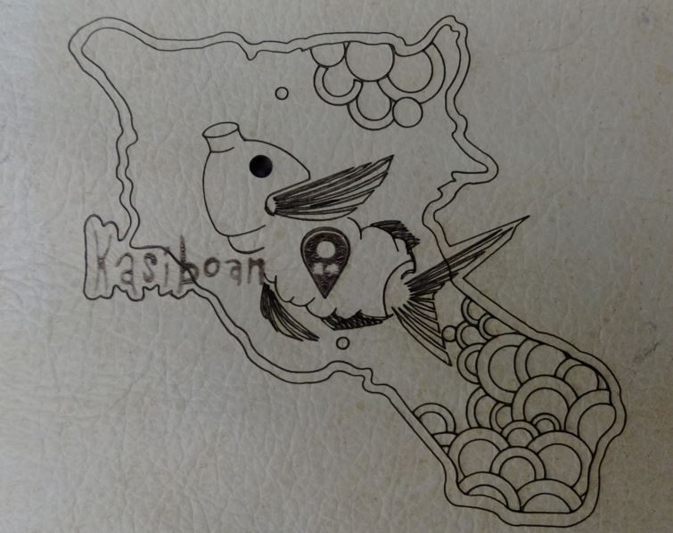
figure 13 : Laser cutting the materials.

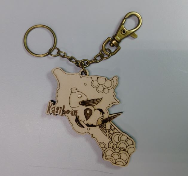
figure 14 : Stick a NFC on the middle wood for following identify phase.
● Silver Helmet and VR Galsses
I hope the person who wears the silver helmet pretend himself as a TAO. Then he watches the dark place of the island via the VR (virtual reality) glasses in the helmet. I hope they can pay attentation to the environmental protection issue.
-- Silver Helmet ---
I had build the silver helmet during the Composites week.
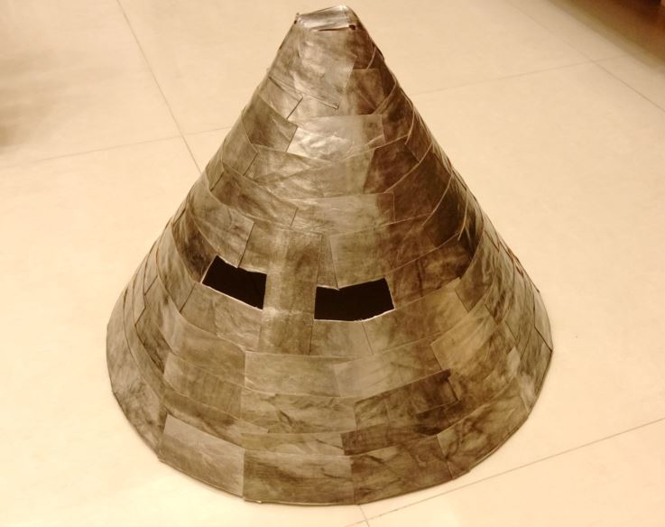
figure 15 : Silver helmet.
-- VR Glasses ---
First, I take google cardboard alike as sample to draw pieces of the VR glasses with CorelDraw. Second, I chose acrylic with 2 mm thickness as the material for laser cutting. Third, I combine all pieces to be a VR glasses. Finally, I put the VR glasses into the silver helmet and fixed them with velcro.
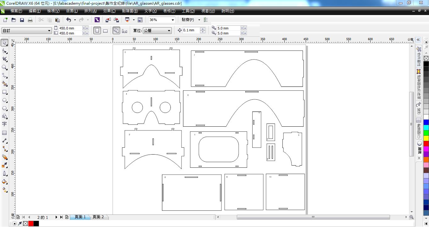
figure 16 : Draw pieces of VR glasses with CorelDraw.
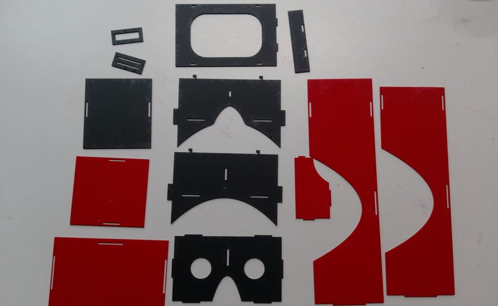
figure 17 : Laser cutting the pieces of VR glasses.
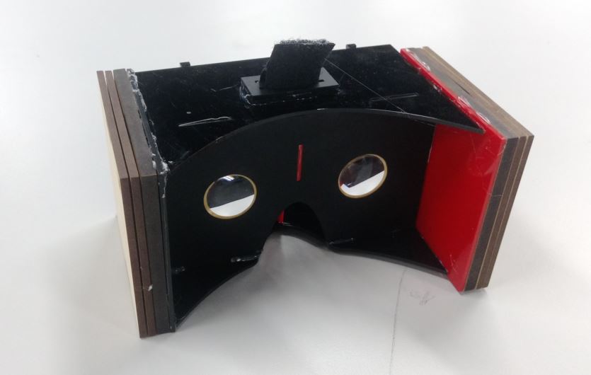
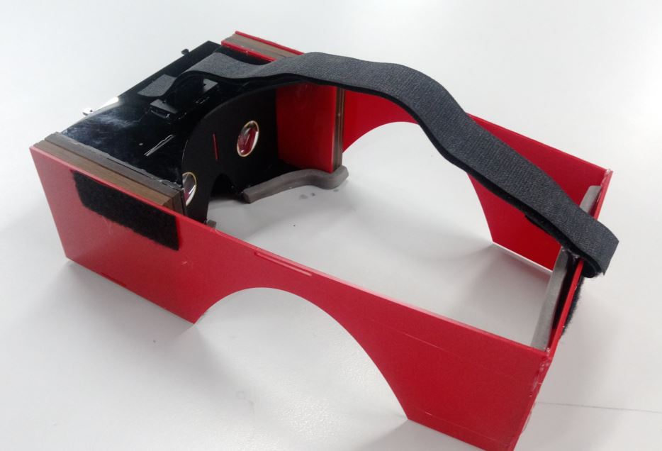
figure 18 : Combine all pieces to the VR glasses.

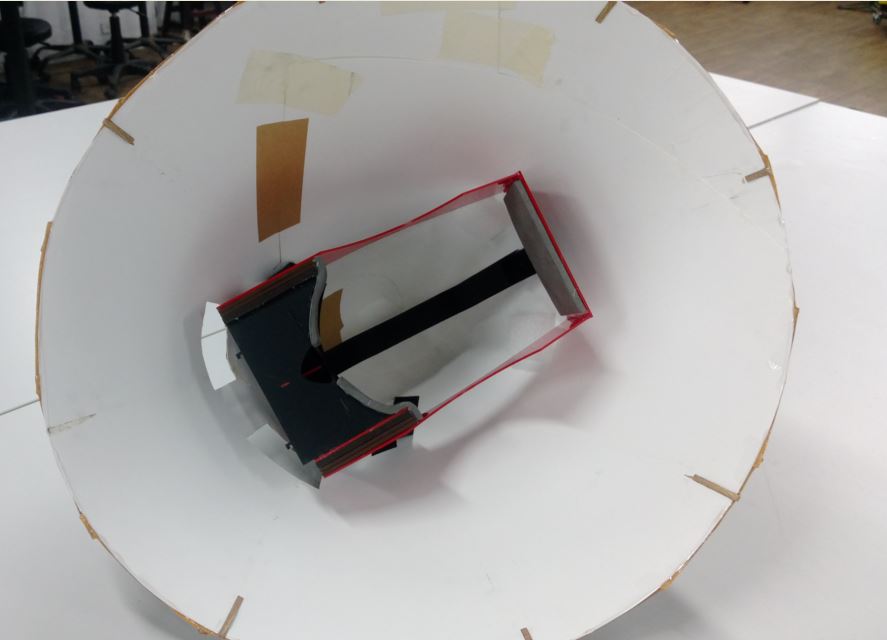
figure 19 : Put VR glasses into the silver helmet.
After finishing the VR glasses, it's time to test the suitability and function, the video is showed as follow :
● Culture Box
I draw the culture box with CorelDraw and the shape is the Orchid island's shape. Then cut the shape with laser cutter. Finally, I combine the box and paint it to let it looks good.
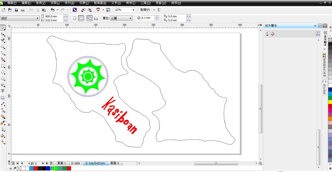
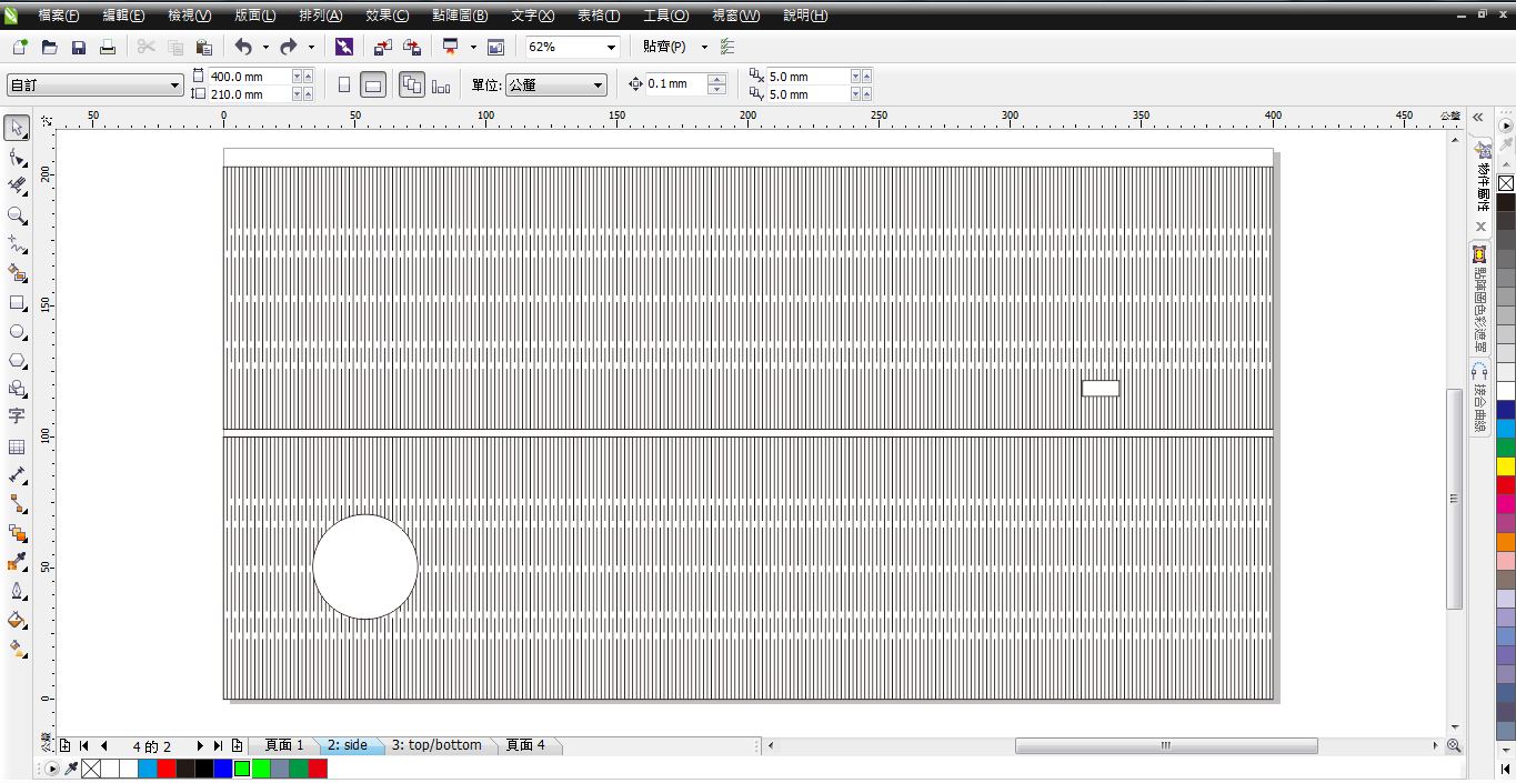
figure 20 : Draw the culture box with CorelDraw.

figure 21 : Laser cutting the box.

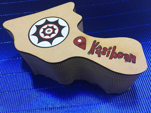
figure 22 : Combine and paint the box.
● Circuits
I use several modules to build the system, such as photocell, RFID RC-522, DFPlayer mp3, speaker, bluetooth and power supply modules.
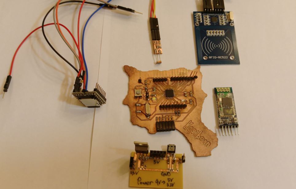

figure 23 : All electronic components used in final project.
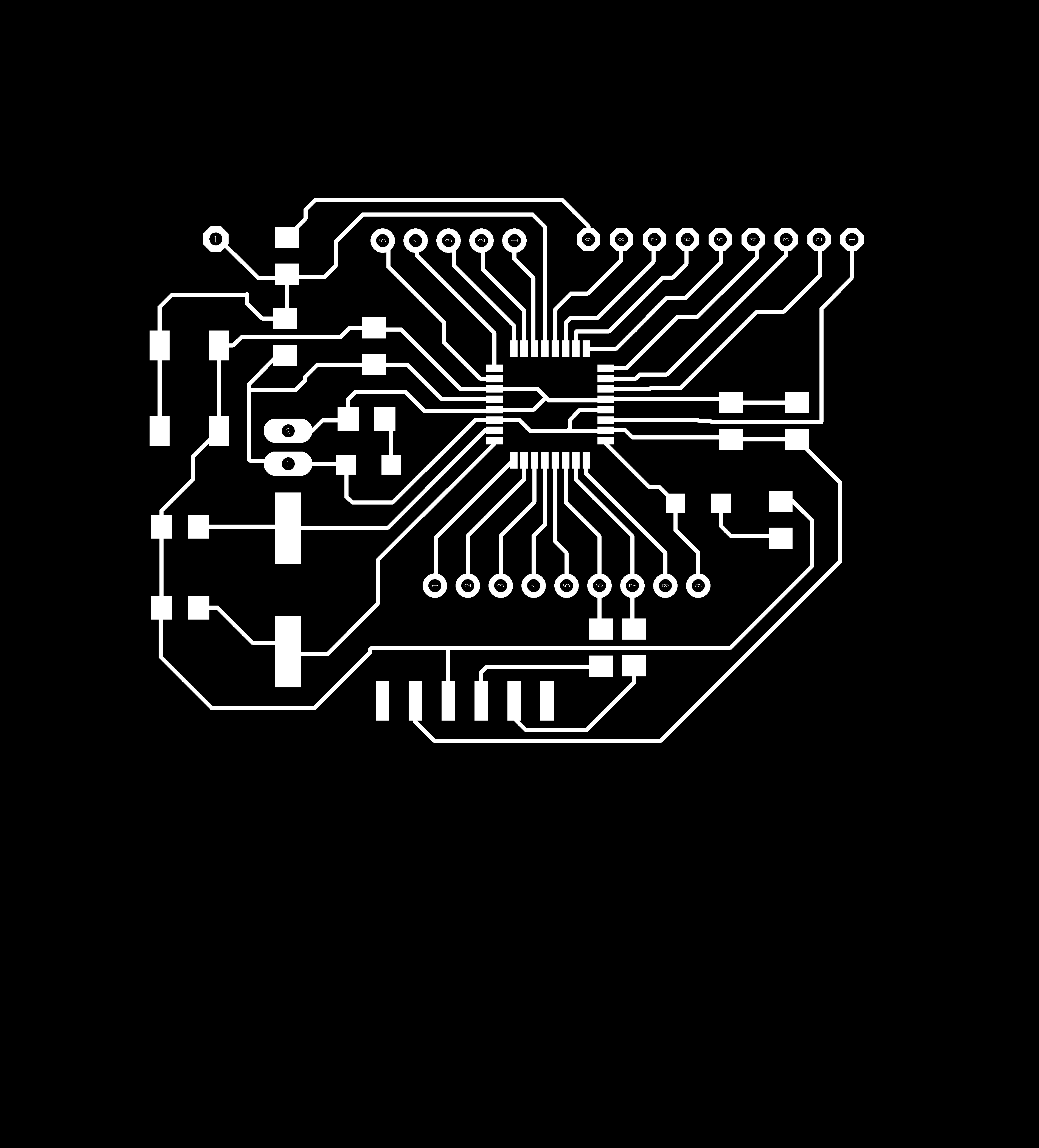
-- Main board ---
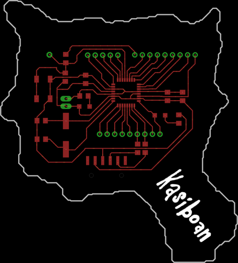
I use the Kasiboan circuit which I had build during Networking and Communications week. But I need more 5V and 3.3V power to supply the sub modules.
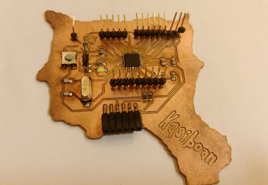
figure 24 : Kasiboan main board.
-- Power Supply board ---
My power supply is 9V, and I use LM7085 to drop the power to 5V, and LD1117 to drop the power to 3.3V. After reading the datasheets about LM7805 and LD1117, I try to draw the circuits of the power supply and use conductive tapes to build circuit board rapidly for testing. After the test is successful, I draw the circuit with Eagle and milling it with Roland Modela MDX-20.
The power supply will supply an 5V power to main board, 3.3V power to RFID RC-522 module, other modules also 5V power.
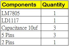
figure 25 : Components require sheet of power supply.
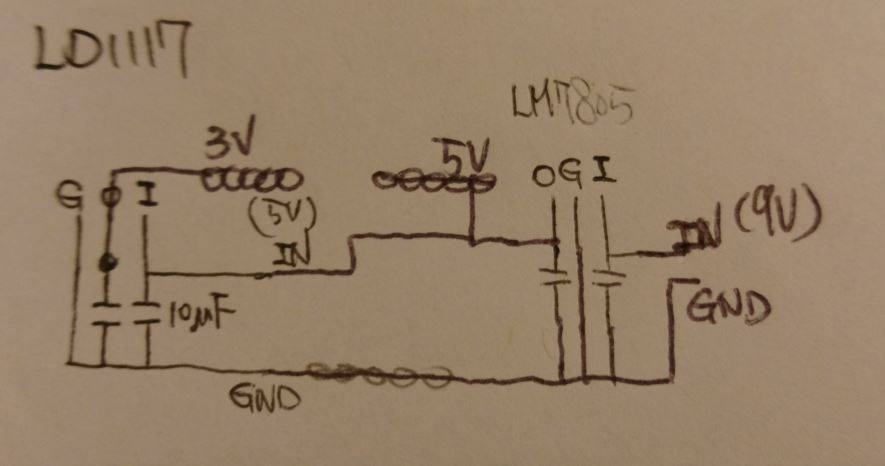
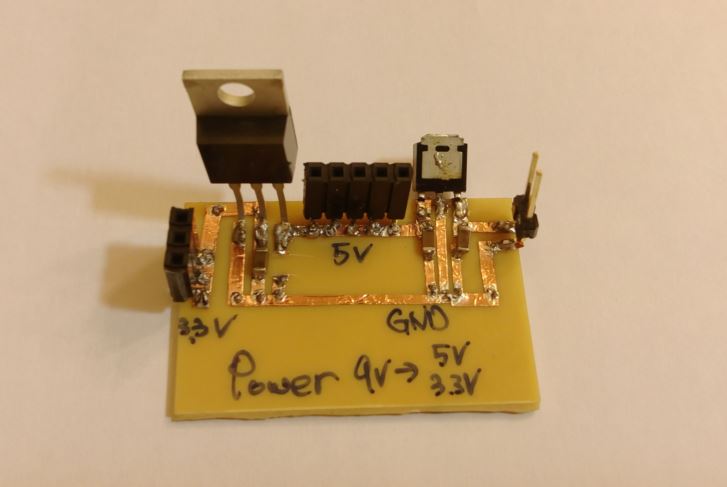
figure 26 : Hand drawed power supply circuit and conductive tapes board.
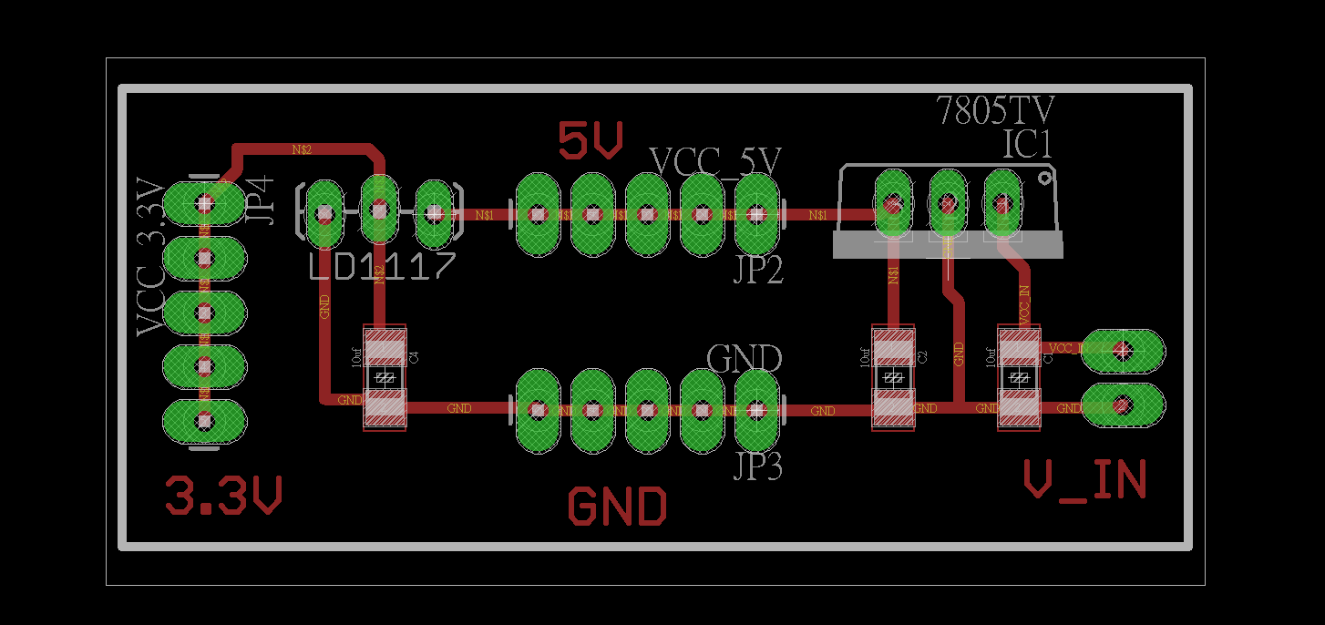
figure 27 : Power supply board which drawed with Eagle.
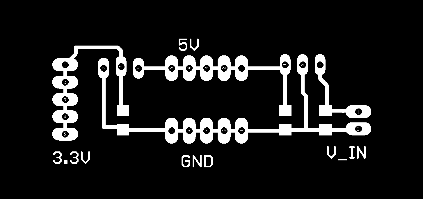

figure 28 : Traces and interior of Power supply board.
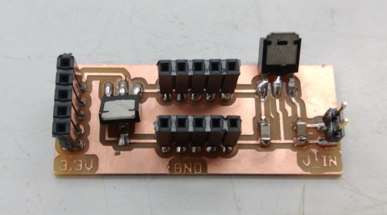
figure 29 : Finish solding the power supply board.
-- Photocell Module ---
I use photocell module as the input device. I set a threshold value for the receiving value from photocell. When the received value is under the threshold value, the RFID RC-522 module turns on and detects the NFC tag.
I draw the circuit with Eagle. There are three pins from photocell module, two connect to 5V and GND on power supply board, third pin connects to the A1 pin on main board.
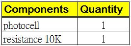
figure 30 : Components require sheet of photocell module.
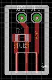
figure 31 : Photocell module which drawed with Eagle.


figure 32 : Traces and interior of photocell module.
I write an GUI with c# to test the photocell module, and the result shows good.
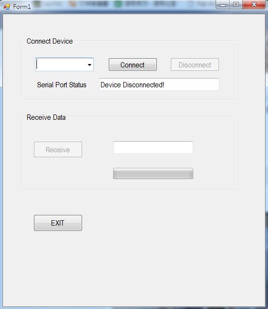
figure 33 : GUI of testing photocell module.
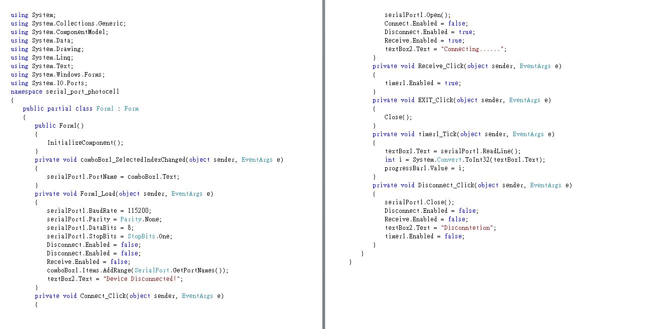
figure 34 : C# codes of GUI.
The testing video is as follow:
-- RFID RC-522 ---
I use RFID RC-522 as one of the the communication modules. When one object put on the culture box, RFID module will detects the object's NFC tag and send message to the main board for following processes. The connection is as follow:
RC-522 3.3V pin --> Power supply board 3.3V
RC-522 RST pin --> main board A0 pin
RC-522 GND pin --> Power supply board GND
RC-522 MISO pin --> main board 12 pin
RC-522 MOSI pin --> main board 11 pin
RC-522 SCK pin --> main board 13 pin
RC-522 SDA pin --> main board 10 pin
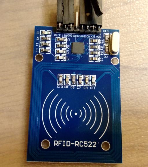
figure 35 : RFID RC-522 module.
I wrote a program to check sum the UID of each NFC tag. I use adduino UNO as the main board and connect with RFID module, and the received UID will show on serial monitor. The c codes are show as follow :
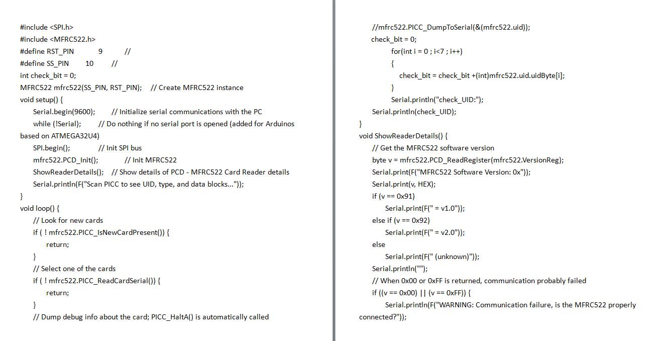
figure 36 : C codes of check NFC's UID.
The testing video is as follow:
-- Bluetooth Module ---
I use Bluetooth HC-05 module to communicate with cellphone which located at the VR glasses. When Key chain put on the culture box, RFID module will detects the its NFC tag and send message to the main board. Then main board will send command to the cellphone via bluetooth to display an VR video. The connection is as follow:
HC-05 VCC pin --> Power supply board 5V
HC-05 TX pin --> main board 06 pin
HC-05 RX pin --> main board 07 pin
HC-05 GND pin --> Power supply board GND
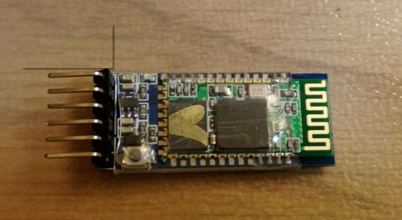
figure 36 : Bluetooth HC-05 module.
I had tested the comunication between bluetooth and cellphone during Interface and application programming week and it works well.
-- DFPlayer mp3 and Speaker ---
DFPlayer is the module which can play the music via plugin the micro sd card. I use this module and speaker as the output device. When the RFID RC-522 detects Eye or Ship's NFC tag, it will send the message to the main board, and the main board will send a command to the DFPlayer to play the relatived music from micro sd card.
The connection is as follow:
DFPlayer VCC pin --> Power supply board 5V
DFPlayer RX pin --> main board 1 pin
DFPlayer TX pin --> main board 0 pin
DFPlayer SPK_1 pin --> Speaker + pin
DFPlayer GND pin --> Power supply board GND
DFPlayer SPK_2 pin --> Speaker - pin
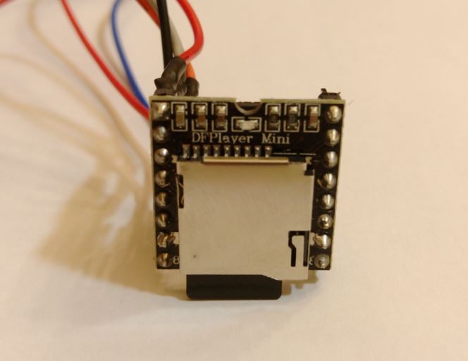
figure 37 : DFPlayer mp3 module.
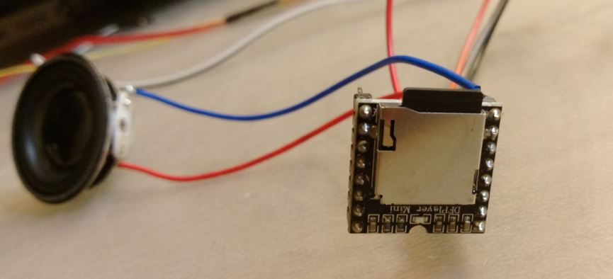
figure 38 : DFPlayer connects to speaker.
I wrote a program to check test the DFPlayer module. I use adduino UNO as the main board and connect with DFPlayer module, the c codes are show as follow :
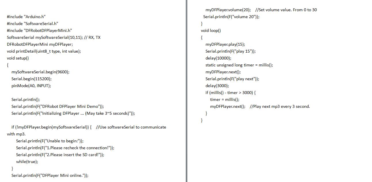
figure 39 : C codes of player music from DFPlayer.
After testing each module, it is time to comebine them into the main board and place into the culture box.
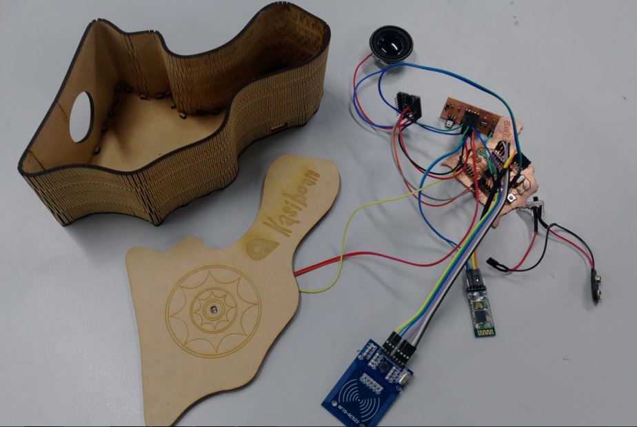
figure 40 : All modules connected to the main board.
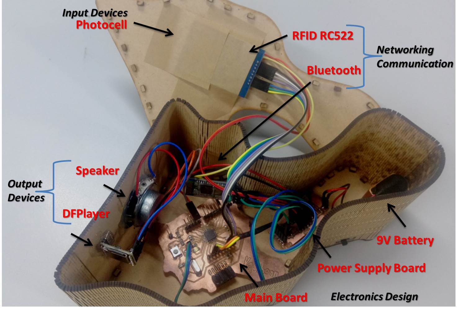
figure 41 : All modules placed into the culture box.
● Programing
The flowchart of the the system and C code with adduino IDE is as follow:
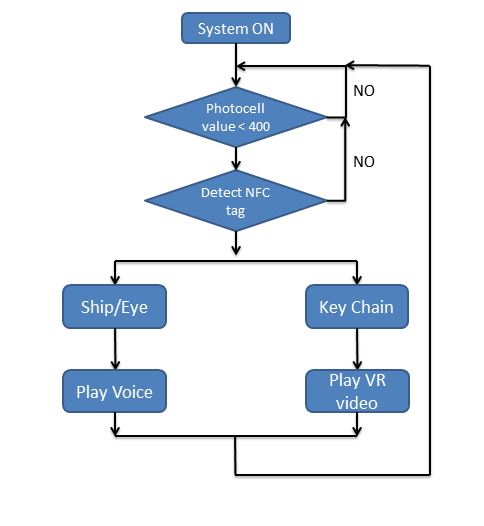
figure 42 : Flowchart of the the system.
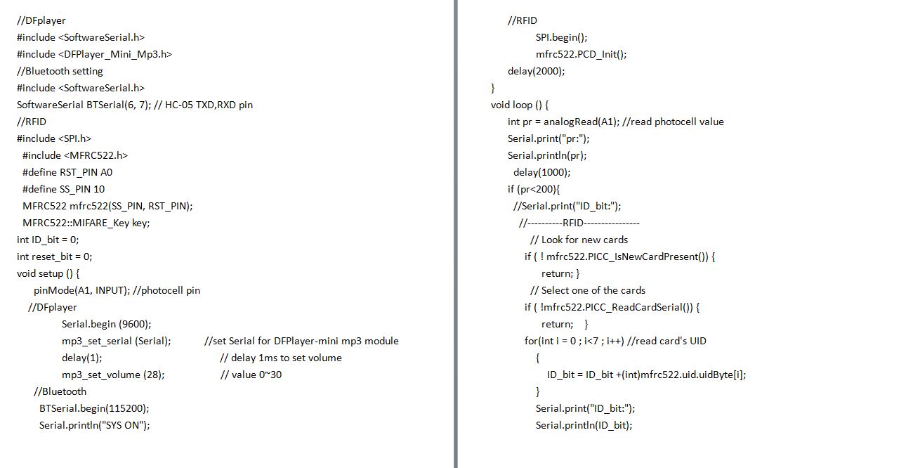

figure 43 : C codes of the system with arduino IDE.
Each part of module was testing good, and integration of all system looks fine. After compiling and programing the main board, the testing of the whole circuit system was good. So the next step is to test the GUI which is in the silver helmet.
● Interface and Application Programming
Once the RFID reader detect the particular NFC tag, the main board will send a message to the cellphone's GUI which located on silver helmet, and the GUI will display an VR video.
I use App Inventor to write an GUI to receive the message from main board and display the video, the app blocks and interface are as follow :
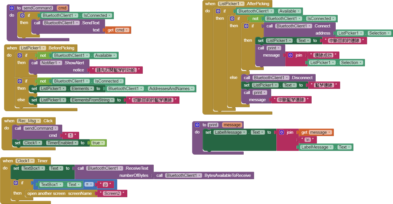
figure 44 : Program blocks of App Inventor.
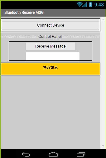
figure 45 : Cellphone GUI of receive message and display VR video.
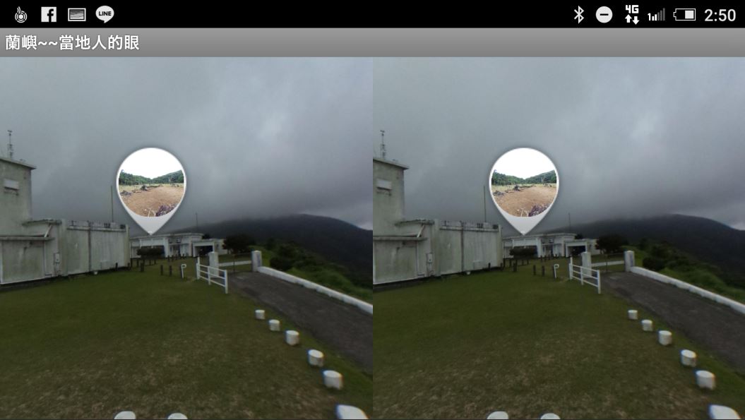
figure 46 : Display VR video from cellphone GUI.
I went to the Rrchid island at April 1st, and recorded some 360 videos about the scenery and Kasiboan. I search on internet to find the free software to program the 360 video, I found "Rundme" can do this. So I edit my VR video on line and setup the link to the GUI. While the GUI receive the message, it would link to "Roundme" and display the VR video. The 360 video I edited is as follow, and it can change to VR mode.
● Problems I met
This project "Exchanged Eyes" is my final project, I integrated several skills I have learned in fab academy. I am so happy to attend the academy and learn so many useful skills.
I met some problems during making this final project, and I spent a few time to solve these problems which discribe as follow :
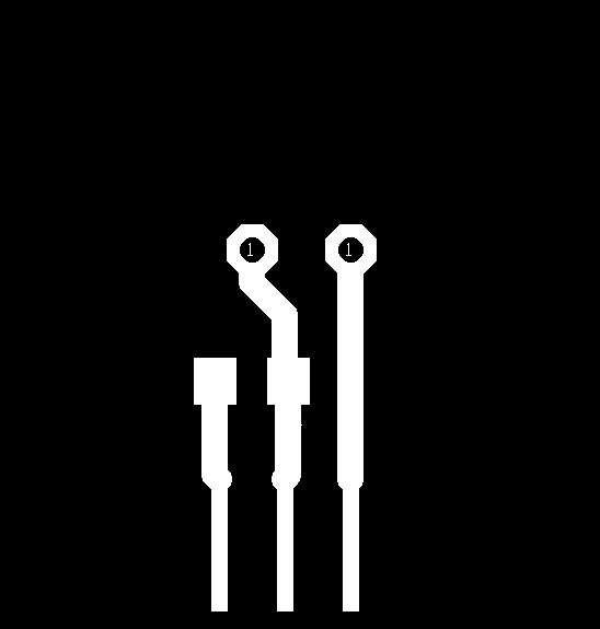
1.Tx/Rx ports insufficient
The assignments for each weeks before were to face the single problem, maybe communication, interface, input or output, what we need to solve would be only one pair of Tx/Rx and it is not difficult. But my final project would integrate bluetooth, DFPlayer and RFID moudles, I need three Tx/Rx ports to make them communication with main board. RFID module use SPI(Serial Peripheral Interface Bus) which apply additional function codes, and I don't want to change the function, so RFID module use pin 10~13 on main board. At the first, I design a external expansion board to let DFPlayer and bluetooth use the same Tx/Rx ports. The external expansion board shows as below. After looking same documents on the internet and testing, I found bluetooth could use pin 6 and 7 as its Tx/Rx ports, and DFPlayer still use pin 0 and 1 as its Tx/Rx ports. So I don't have to use the external expansion board.
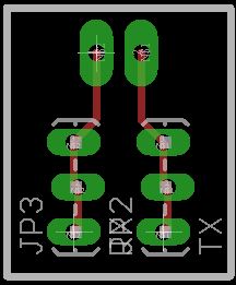
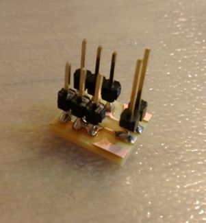
figure 47 : External expansion Tx/Rx board.
2.360 videos format converted
This is my first contact with 360 video, and I spent a a few time to find how to convert it and show on the helmet. There are several tools can do this work, such as "Roundme", "THETAS", "THETA+", etc. I try those softwares to make my VR video and found "Roundme" is easy and useful for me. Finally I decide to use "Roundme" to make my VR video.

This work is licensed under a Creative Commons Attribution-NonCommercial 4.0 International License
.
● Source file
1. STL file of object "Eye".
2.STL file of object "Ship".
3. Rhino file of object "Ship".
4. CorelDraw file of object "Key Chain".
5. CorelDraw file of Box.
6. Traces of main circuiit board.
7. Interior of main circuiit board.
8. Schematic of main circuiit board.
9. PCB of main circuiit board.
10. Datasheet of LD1117.
11. Traces of photocell circuit board.
12. Interior of photocell circuit board.
13. Traces of power supply board.
14. Interior of power supply board.
15. Schematic of power supply board.
16. PCB of power supply board.
17. C codes of testing photocell module.
18. C# base interface of testing photocell module.
19. C codes of testing RFID module.
20. C codes of testing DFPlayer modules.
21. APK file of GUI.
22. AIA file of GUI.
23. CorelDraw file of VR glasses.
24. C codes of whole system.