Week15 : Networking and Communications
The assignment of this week :
● Design and build a wired &/or wireless network connecting at least two processors.
● Demonstrate workflows used in network design and construction.
● Implement and interpret networking protocols.
My workflew of networking and communications is as follow:
1.Design and milling a new circuit board.
2.Test bluetooth module HC-05 master and slave mode.
3.Buiid and demonstrate the communcation between two processors.
● Design and milling a new circuit board
At the 13th week(Input Device), I designed a circuit board with MCU ATmega328 was tested fail. So I try to do it again this week. Relating to my final project, I use the shape of Orchid Island as the circuit board's shape.
The steps to draw the shape are as follow. First, in the Eagle BRD screen, I choose the "Line" function, proper "Line style", and the layer set to "20 Dimension". Then drawing the shape carefully.
After soldering and checking the joints carefully, the circuit board finally works.
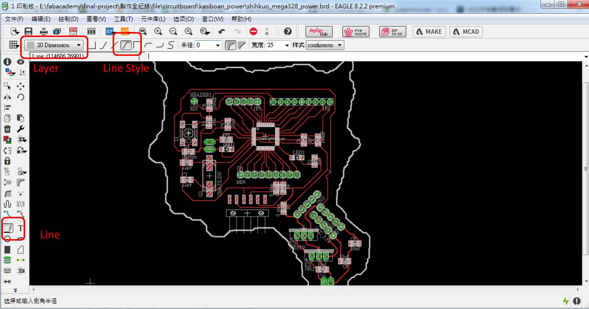
figure 1 : Draw the shape.
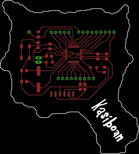
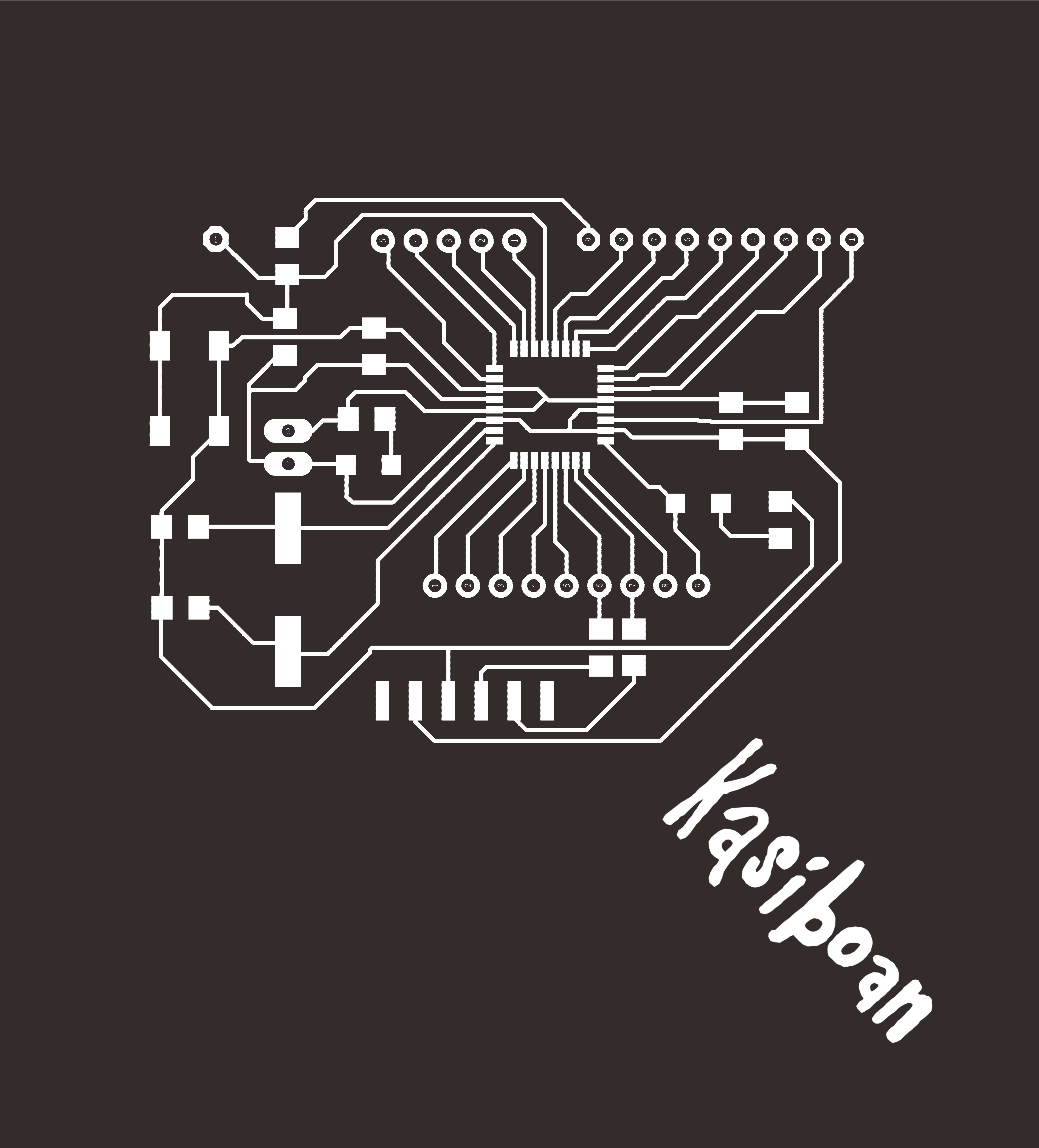
figure 2 : Kasiboan circuit board.

figure 3 : Traces of Kasiboan circuit board.

figure 4 : Interior of Kasiboan circuit board.
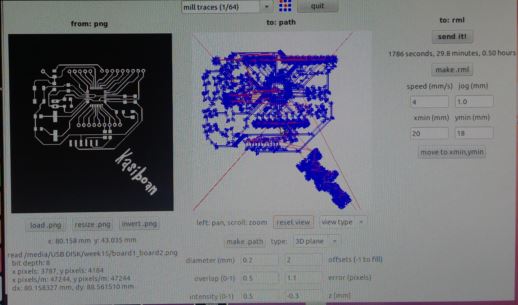
figure 5 : Set milling parameters with fab module.
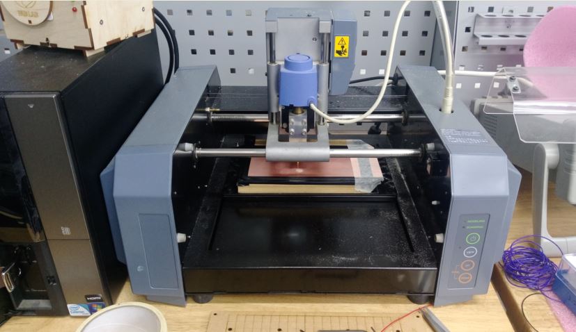
figure 6 : Milling the PCB with Roland Modela MDX-20.
The setting of milling the traces is as below:
Type:3D plane
diameter(mm):0.2
Offsets:1
Overlap:0.5
error(pixels):1.1
intensity:0.5
z(mm):-0.3
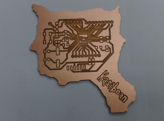
figure 7 : Milling result of PCB.
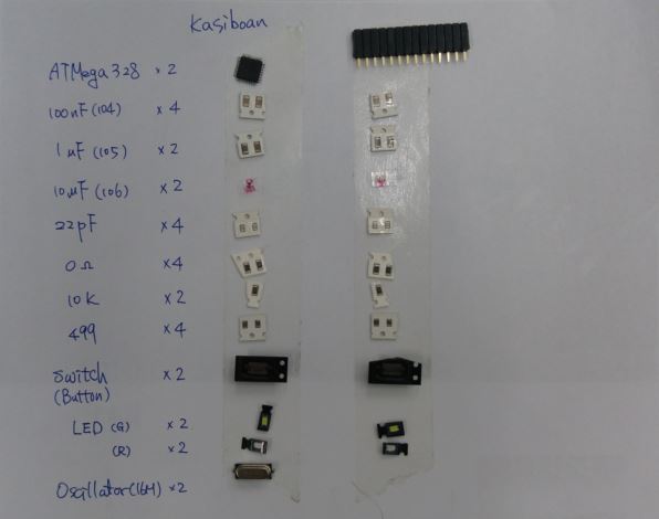
figure 8 : Components of Kasiboan circuit board.
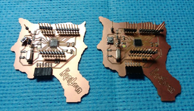
figure 9 : Finish soldering.
I use arduino UNO as ISP to burn the bootloader and programs. The connection between UNO and Kasiboan kit is as follow.
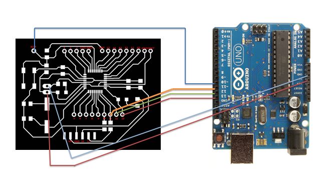
figure 10 : Connection between UNO and Kasiboan kit.
It is important that while programing the board using MCU ATmega328, we need to chose "sketch -> Upload using programer" instand of chose "Upload" on the arduino IDE. After that, my Kasiboan kit works well.
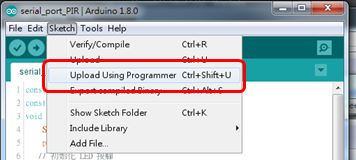
figure 11 : "sketch -> Upload using programer" to upload the program.
● Test bluetooth module HC-05 master and slave mode
I use bluetooth modules to communicate with two processors. The bluetooth module I used is HC-05. HC-05 could be both the master and slave. But I need to set these two HC-05 up to the proper role and parameters at first.
So I use the AT command mode to setup HC-05.
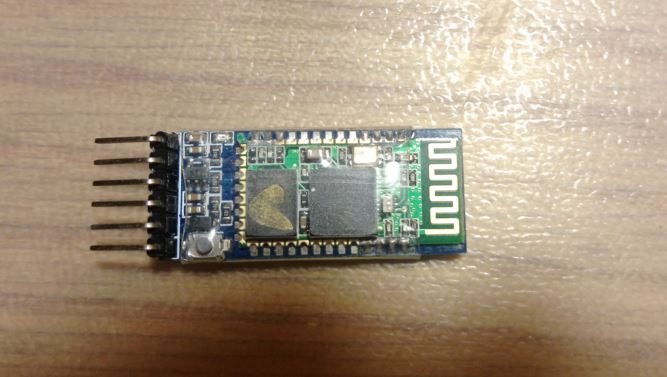
figure 12 : Bluetooth module HC-05.
Before setting HC-05, I read the datasheet to know the specifications. I use arduino UNO to setup the HC-05, the connection between UNO and HC-05 is as follow :
HC-05 VCC → Arduino 5V
HC-05 GND → Arduino GND
HC-05 TXD → Arduino pin 10
HC-05 RXD → Arduino pin 11
HC-05 KEY → Arduino pin 9
My HC-05 version has a button on it. I need to push this button and plugin to the UNO at the same time to set HC-05 into AT command mode.
Then I write a AT command program with arduino IDE and set AT command with terminal.
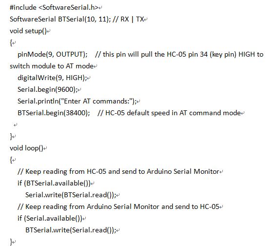
figure 13 : AT command program.
The role master and slave on HC-05 has different setting on AT command. The related AT command is as follow:
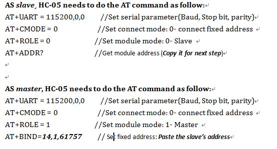
figure 14 : AT command setting on master and slave.
But I send any AT command to HC-05 via terminal and it only replies "OK" and I complete the setting of master and slave mode of HC-05.
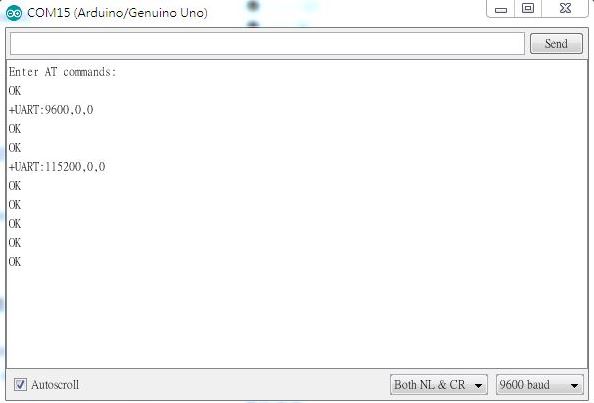
figure 15 : AT command replies on terminal.
● Buiid and demonstrate the communcation between two processors
I use bluetooth module to communcate with two circuit board, one is kasiboan circuit board with MCU ATmega328 and another is I made it on week 8 (Embedded Programming) with MCU ATtiny44.
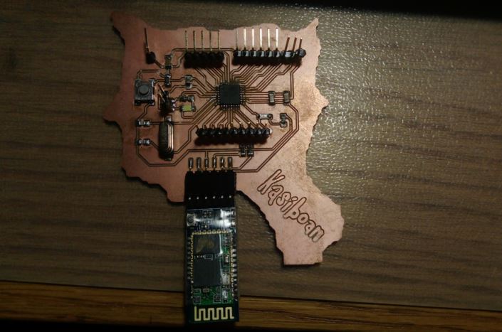
figure 16 : Kasiboan circuit board with MCU ATmega328.
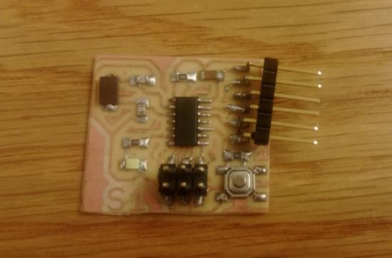
figure 17 : Second circuit board with MCU ATtiny44.
The networking protocols I want to show is as follow :
1.The master (Kasiboan circuit board) send a message to the slave (second circuit board).
2.While the slave recives the message, it will blinking the LED with 2 second. Then it will delays 5 second and recives message again.
I write two different progarms for the master and slave board. The power of two boards is supplied from arduino UNO. The networking of these two boards is good. The vedio of two processors wireless communication is as follow :
● Source file
1. Traces of Kasiboan circuit board.
2. Interior of Kasiboan circuit board.
3. Schematic of Kasiboan circuit board.
4. PCB board of Kasiboan circuit board.
5. AT command program codes.
6. Master board program codes.
7. Slave board program codes.