Week 20 June 7th: Project Development/Presentations
Final Project: FabCase, the FabAcademy computer case
After going through several years worth of FabAcademy projects and realizing that even though every single person in this program would possess or have access to a computer, no one had actually built a computer case to my knowledge. So I decided to choose a pragmatic project that would be straight-forward to make and replicate, as well as being cool and appealing to my nerdiness.
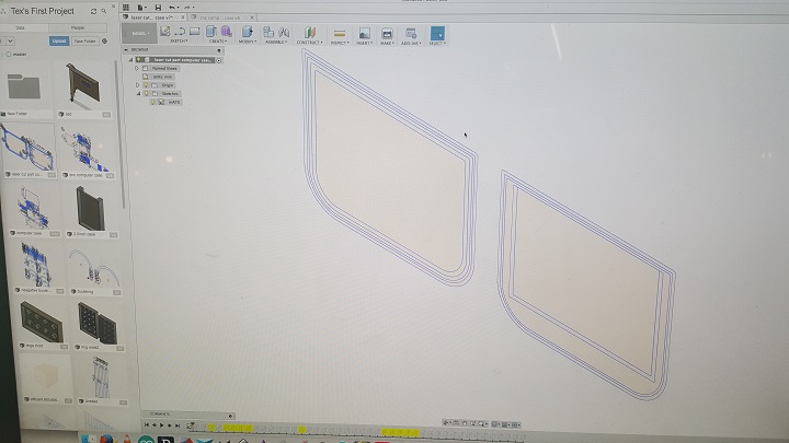
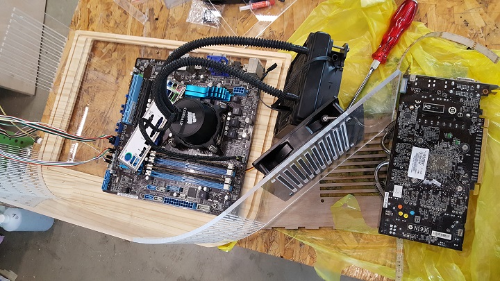
I started designing a simple box with laser cut finger joint edges, so I can find out the neccessary size of the computer case and also correctly measure and test the fit of the motherboard screw holes, the I/O panel, the exit holes for the GPU and power supply unit, fan cage holders, and other details. I modeled the case in Fusion360 and using a standard micro-ATX motherboard to fit in the box. After several iterations and mistakes and "gods I can't believe I forgot to add this again", I finished with a prototype of the case. From here I realized this was basically a fancy shoebox and with some additional suggestions and tweaking, I improved upon the design of the case. So after the prototype I found that I need about 900mm by 600mm plate of 5mm acylic(30USD), one 12mm piece of nice looking 1000mm by 500mm wood(found so free but about 20USD), some random screws and bolts(5USD), the computer components(based on what you have), some electronics and thermal paste(5USD), and lots and lots of wires from your previous projectsthat cost a total about 60USD in total to buy.
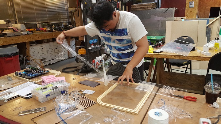
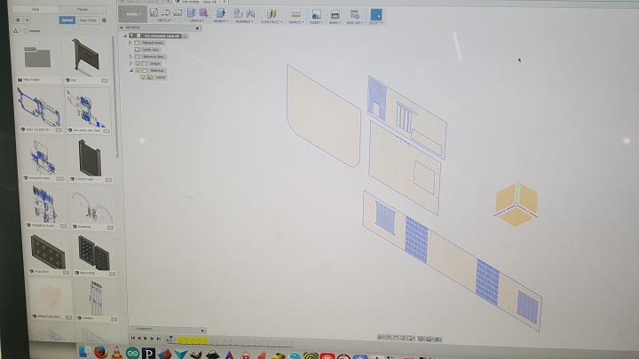
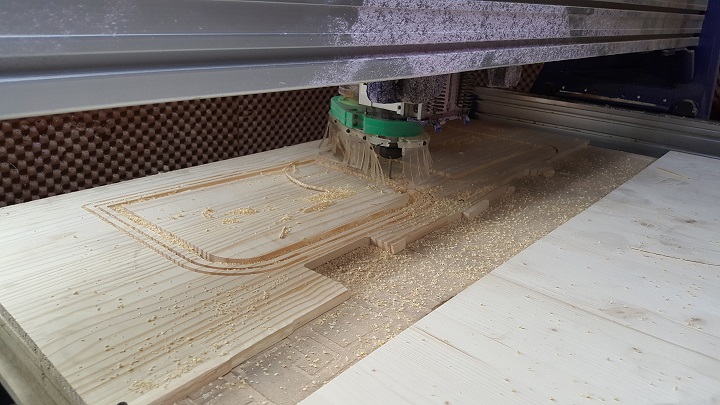
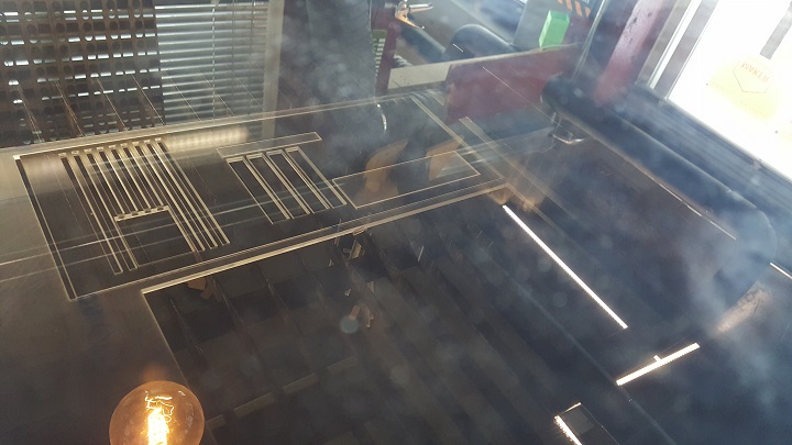
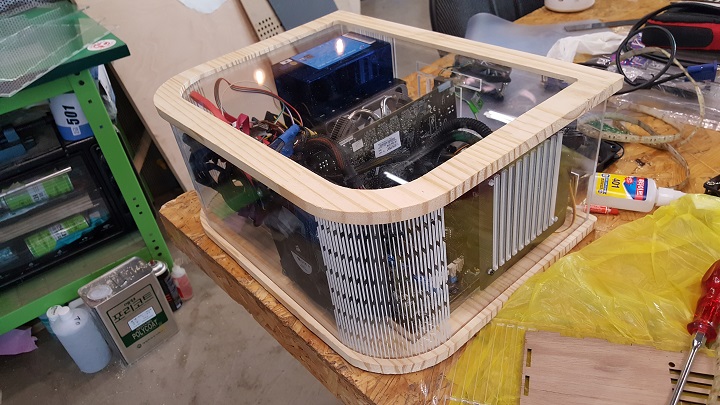
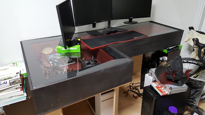
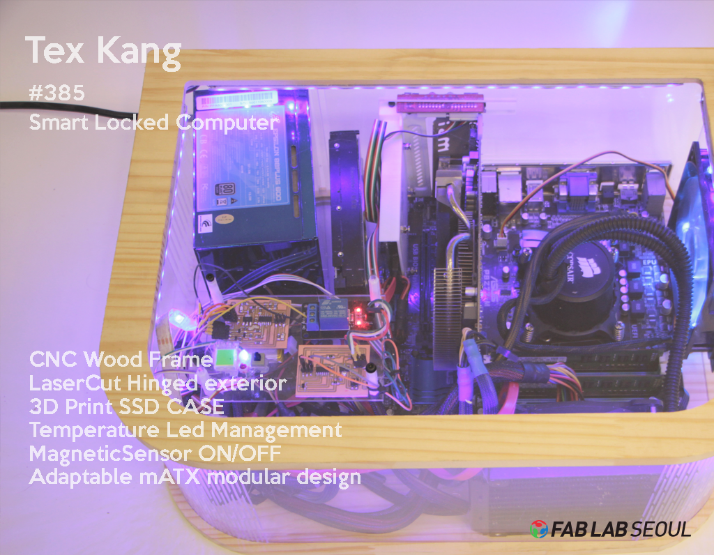
First, I CNC'd some nice light wood of 12mm thickness to be the base and top of the case. I added windows on each side which allows me to change the motherboard easily(to another one and/or to a different size) by switching the acrylic panel that lies on the wood, and then added a grooves so I can place the lasercut acrylic walls. For the back wall I used a standard pane of acrylic with the motherboard I/O panel holes and other spaces for the computer components. For the side and front, I used one 900mm long piece of 5mm acrylic and using a living hinge made a very nice looking and functional wall. In additional to having the living hinge, it serves as additional inlet holes that can help ventilate the case. I already installed an extra computer fan that pulls air out so the case now has a decent air pressure space.
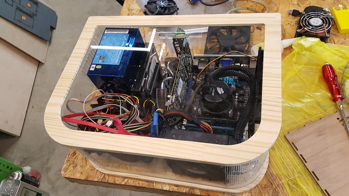
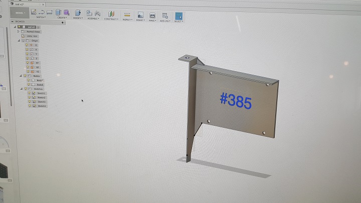
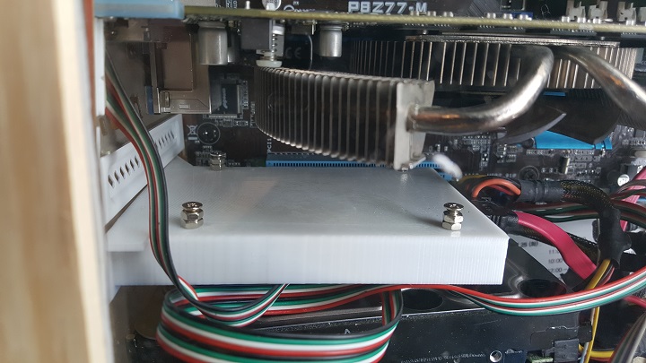
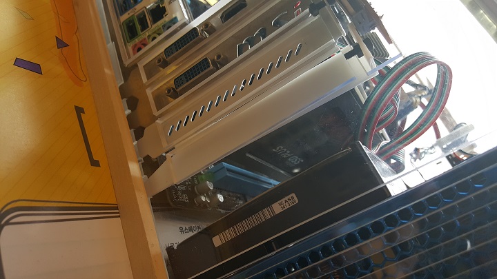
Luckily the living hinge wall fit perfectly inside the CNC and the only thing I adjusted was to cut 5mm off on each side of the back wall to accomodate the panel. I screwed in the computer parts and installed the wires and everything seemed to fit in snugly enough. After I started working on a 3D design for house my SSD card. I chose to design a 2.5" housing that would fit the SSD card right below the GPU card in an empty PCI slot, so it would save space and be secured to the case. I found out the dimensions of the SSD's screws locations and then measured the graphics card PCI screw panel and just made a very simple design in Fusion, and then printed it out. After that was done, I moved on to building the electronics for the LEDs.
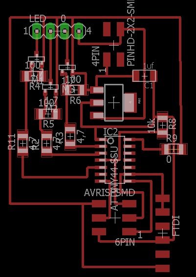
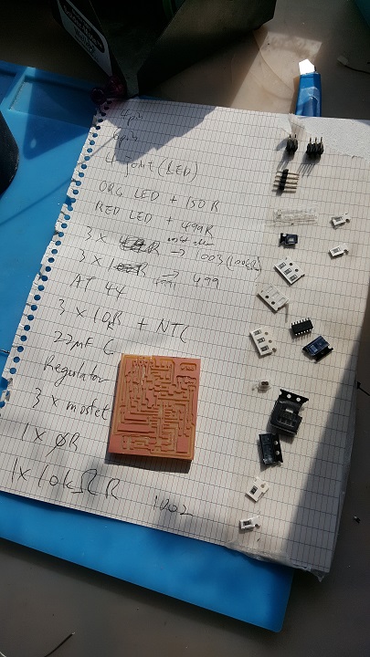
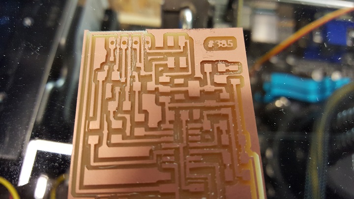
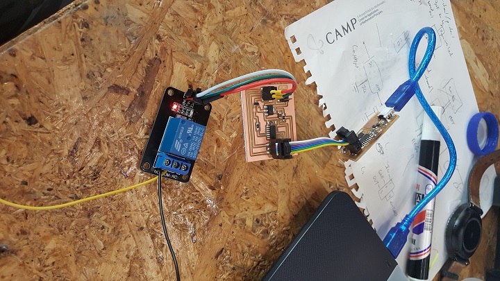
I used Eagle to design a PCB that would house 3 mosfets for each RGB colour and one voltage regulator so I can power it using the 12v PSU's molex connector. By doing this, I would save having to use an USB port for the PCB and also the LED strip would run directly on the 12V source. There is also a temperature sensor in the PCB which allows the LED strip to change colours depending on the ambient temperature. The code I used was a simple code where I learned from Arduino Playground http://playground.arduino.cc/ComponentLib/Thermistor2 and by converting the values you get in to Celsius and then assigning ranges for specific values, you can code a simple fading light program into the attiny. Since the LED strip was powered by 12v I snipped off a molex connector and connected the power and ground wires on it to the LED pcb so now it would be powered by the computer's power supply.
After extending the LED strip and installing in under the top panel, Edu suggested to add another cool function to my project, a magnetic hall sensor. If anyone has seen the premiere episode of Season 3 Rick and Morty, they might have seen a scene where one of the character tries to rearrange some dead flies on a table to activate a table. I wanted to use the same concept by 3d printing some "dead flies" around some magnets and installing the PCB for my desk sized not so desktop laptop(I CNC'd a 2meter long computer desk with an internal space that holds a laptop motherboard powered by a jerryrigged external GPU and some other computer parts that are normally not used by anyone sane), which I still will but due to the limited asthetic space on this particular final project I could only put one.
Anywho, I installed a magnetic sensor with it being connected to a relay, a fantastically useful device which allows a circuit to be connected physcially or not, depending on data being sent to it. So it converts my magnetic sensor input to a power on/off switch basically.
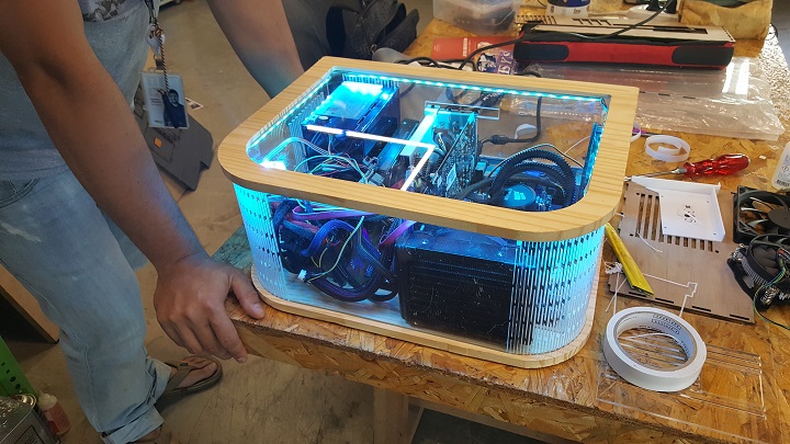
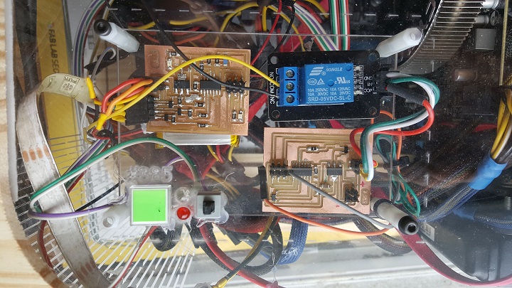
After that I installed both PCBs and other fab components on a small acrylic plate with the power/reset buttons with the indicator LEDs and that was installed on the left bottom size of the top panel, so anyone can see the wiring and where to place the magnet to turn on the computer.
And so my final project was finished. It's works fine and I've installed Overwatch and played it with no problems. I reused some concepts from my 3D designing and printing weeks and input and output weeks but improved upon like the lasercutting by adding living hinges, and adding different standard electrical components to my custom PCBs. I wish I had time to include more functions as my case was big enough that it could easily accomodate things. I encountered many issues, ranging from finding the exact dimensions of the modular but very sensitive computer components locations, finding the correct bending ratio of the living hinge based on its cuts, finding the neccessary and minimum thickness of the walls to support the parts and the top, some power issues where I realized that due to the old PSU's nature, it didn't have a passive power port I can use directly which meant that when the computer was off, the molex connector powering the magnetic sensor PCB was off, which would not allow me to power the computer(I had to install another custom PCB connected to a lipo battery so when its on it would charge the battery and when its off, it would power the PCB). Some problems I did face and had to work around was when I wanted to use molding and casting to mold something(dead flies) around a magnet. However I didn't do injection molding so the mold came out unfortunately unusable. I plan to 3D print a hollow fat dead fly and in the middle of the print, glue gun a magnet in the center and then let the print cover it naturally. On my next upgrade for this project, I plan to add a network system so I can remote access it anywhere as well as being able to turn on, get notifications, etc on my phone using my home's WiFi router.
Design files Download
Special thanks to Eduardo for helping me with the ideas, slide and video, and generally being a great instructor. Fablab Seoul will miss him.

This work is licensed under a Creative Commons Attribution-NonCommercial-ShareAlike 4.0 International License.