Week 10 March 29th: Output Devices
LEDs are cool and shiny
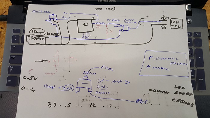
LEDs are awesome. They make anything awesome already even more awesome like bikes, computer cases/desks, drones, monitor backlights, etc. So even before seeing this week's assignment I wanted to make a circuit board to power LED strips so I was much more enthusiastic and motivated that as I am right now writing about how it still continues to surprise me how tedious and annoying electronics are. Seriously, all electrical engineers deserve a lot of respect for surviving college. I started with looking at the RGB LED board, and seeing as how it has dedicated RGB pins that connect to the attiny, I wanted to use the similar components but expand on it. However I learned that there was much more things to take into consideration such as calculating the voltage changing from 12V to 5V for the processor but maintaining it for the LED strip, accounting for acceptable ampere rates for the new components(I added a n mosfet to regulate the flow to allow things like fading) and designing the board without having to add a ridiculous amount of 0 resistors to skip over the routes.
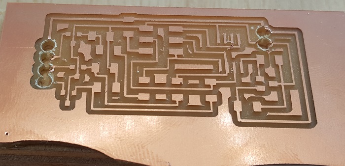
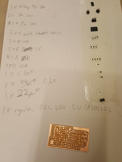
So I cut it but of course 2 interesting and new things went wrong this time. One was that I forgot to flip the inside/outside cut on the holes so the holes came out much bigger. Secondly the outline file was somehow the wrong dimensions and was much bigger than the actual size of the board. So I did what I usually do, document and learn from my mistakes and then turn to more conventional and ghetto ways to fix it. So after an excess amount of soldering and using needle pliers I got the board fixed. Another interesting fact I did find entertainingly enough was when I showed this board to my instructor and he immediately said "wtf?!". I named the board the same as well.
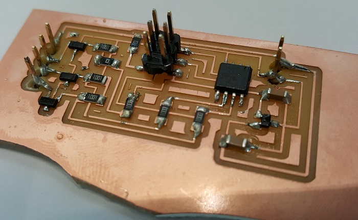
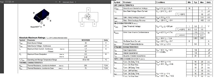
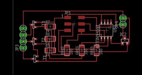
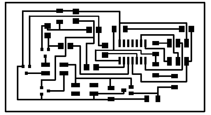
So after some further research and when I plugged the board and it didn't immediately blow up, but the area where the capacitors were were getting somewhat very warm. Concerningly warm. So I think I basically did some calculations wrong regarding the current and amperes. So as interesting as this board in concept was, it was kaput and I started to desolder and start over. After an hour or so of reading the wrong datasheets and then reading the right ones I changed the design and also used different components such as a different out pin(albiet I fear this will be the end of this device in the future when I forget where the power pins go) and a different regulator which will hopefully be easier to solder. I also used 4 0K Resistors but I could probably use a couple wires instead if that makes it easier in the near future). And here lies the designs what I hopefully think will actually work, as well the code I used to power it that compiled correctly so I hope it will work on the board.


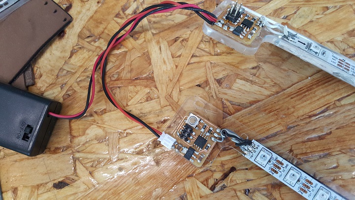
After soldering and flashing the software, I plugged in the RGB strip and programed a simple on to fade to lower brightness and back again, where all the values of the RGB were set to max first and then added delay and then repeated but with lower but same values of the RGB to create the white light.

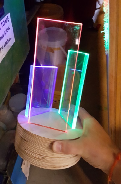
Using the above methods, I started to branch out a bit more and learned to make more functional lights such as bike wheel lights you can zip tie to your spokes and non-functional RGB lights that do nothing but light up pretty like.
This is the Eagle design files: Download .brd file Download .sch file