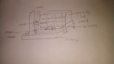
The sketch
I began with a hand made sketch of the idea as shown below.
2D models
2D and 3D Design
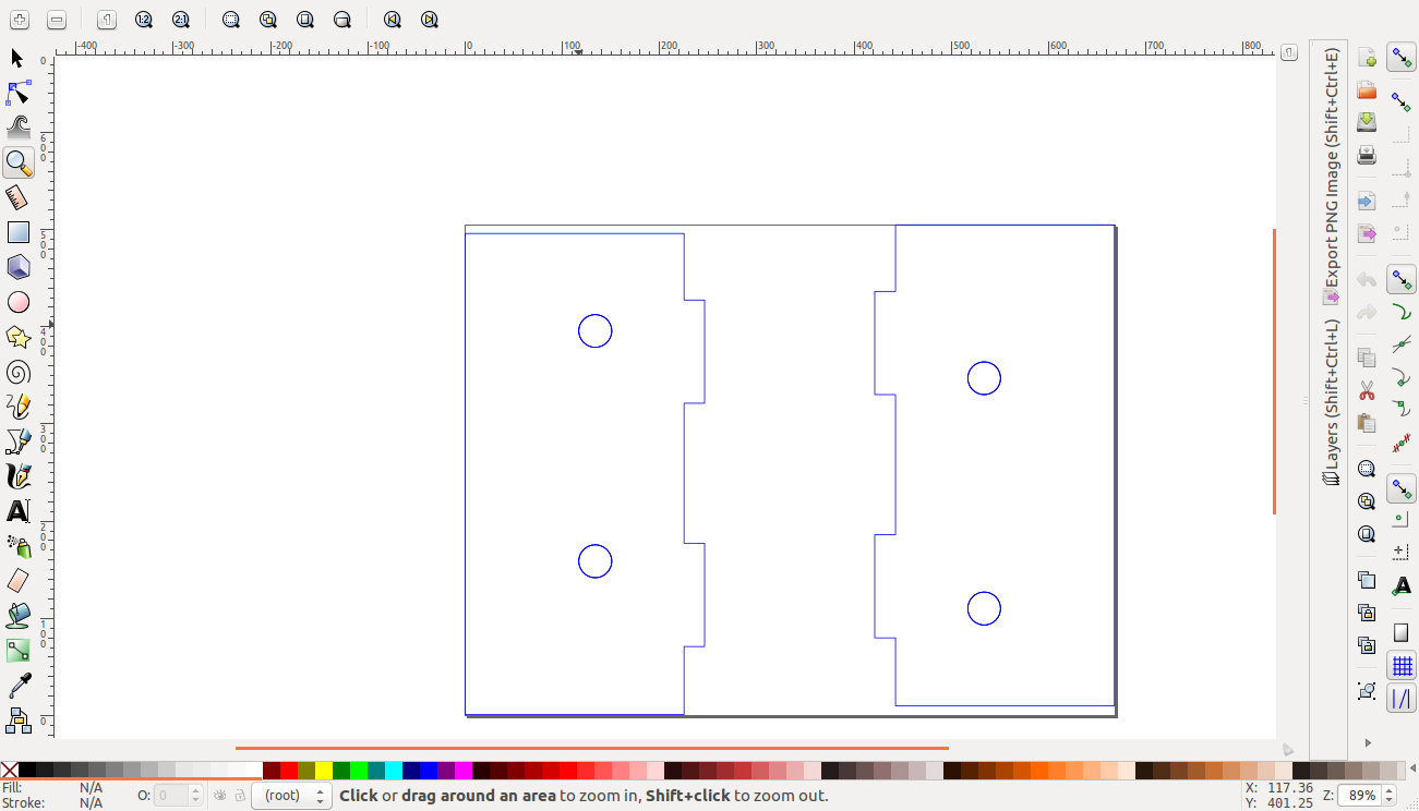
The Cardboard stages
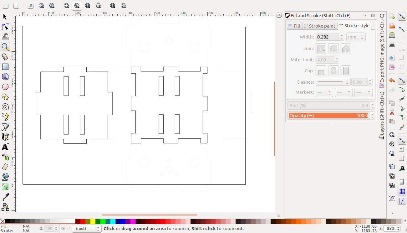
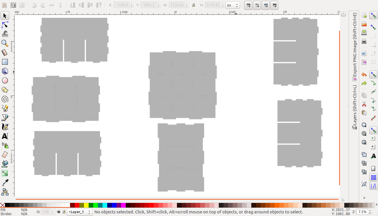
The first order of business was to redesign the stages. I took the designs designed for uline cardboard. I had to redesign for them to fit 6.5mm cardboard and eliminate the folding lines. I began with changing it from a trifold design to a press-fit design as shown. for the side pieces i had to change the positioning of the holes to align due to the modification.
sides
I then redesigned the rest of the box
outer box
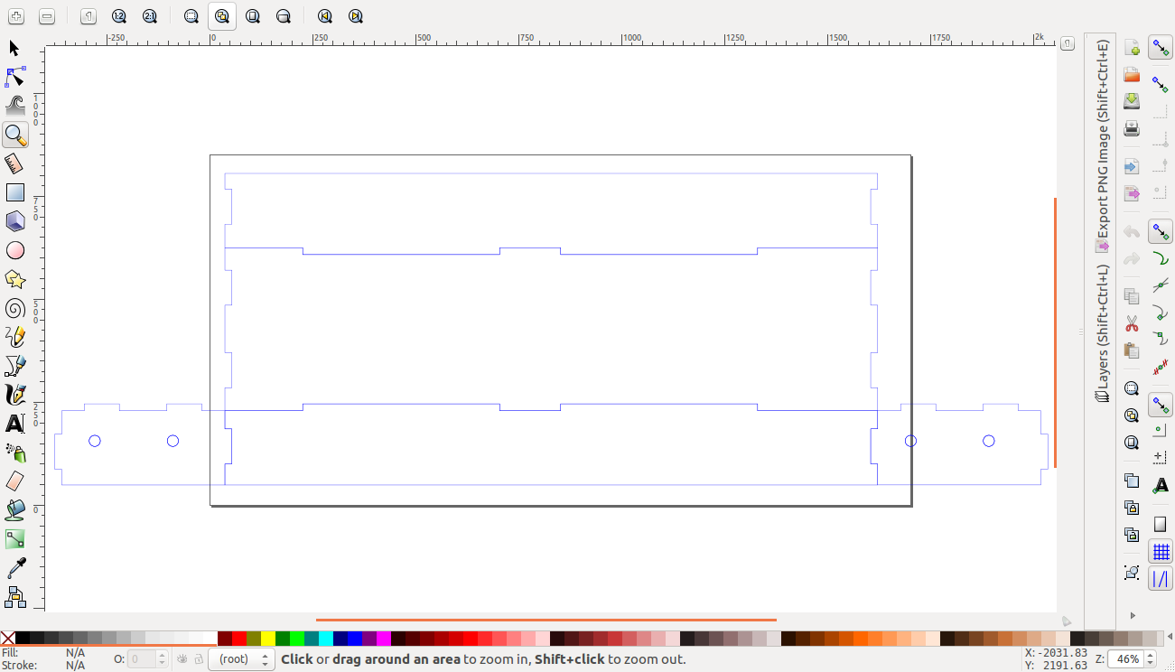
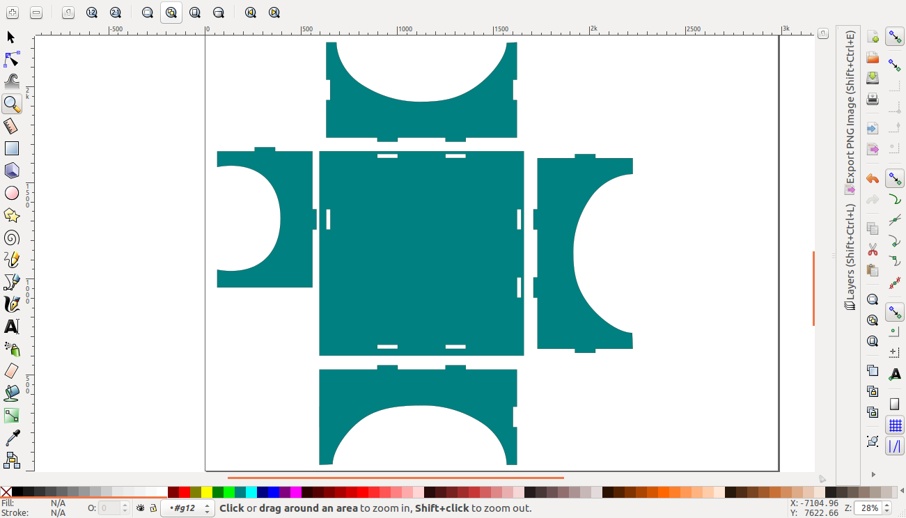
I then proceeded to modify the inner box. This took alot of trial and error before getting it to fit right. i had to change the sizes of the top and bottom piece since this was no longer a trifold design. I also eliminated two pairs of the holes on the top piece that were meant for the folding pieces.
inner box
top and bottom piece
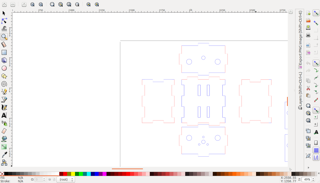
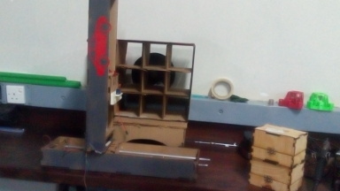
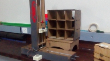
When cut out the outcome was as shown
The inner contents of the axis
The two axes
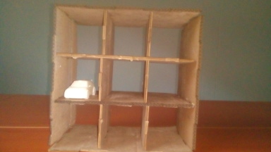
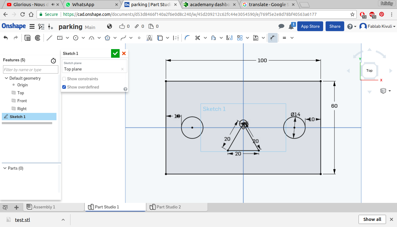
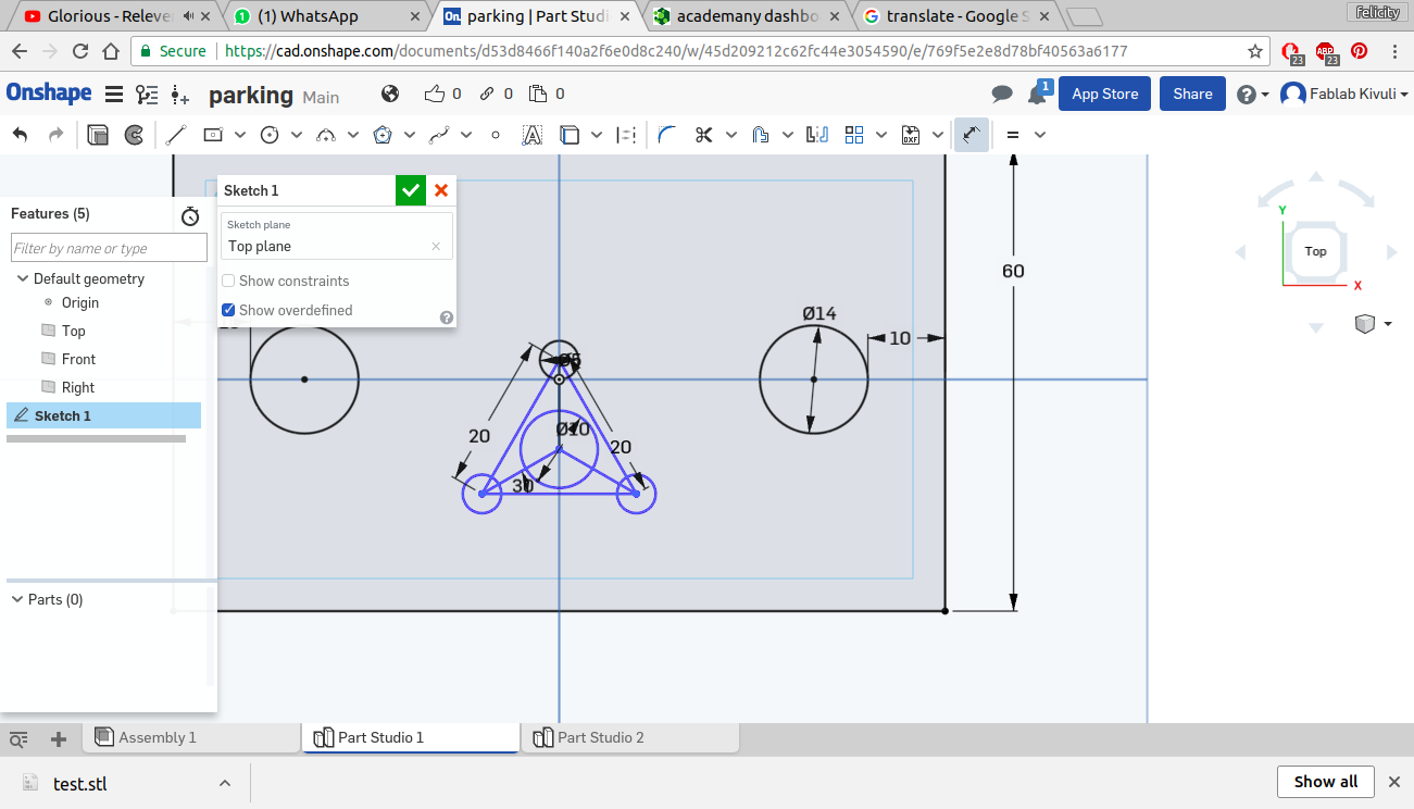
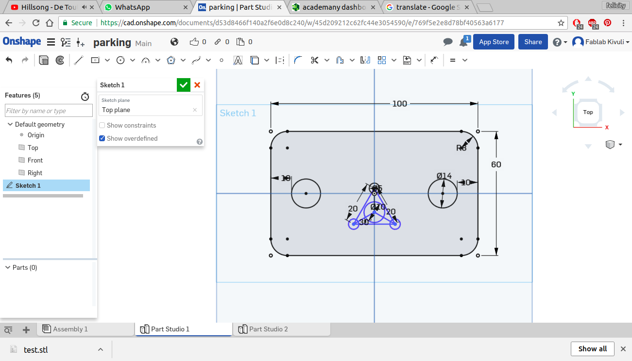
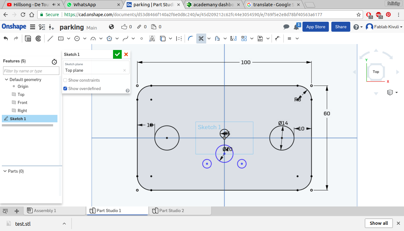
I then designed the stage and the model parking lot
The platform
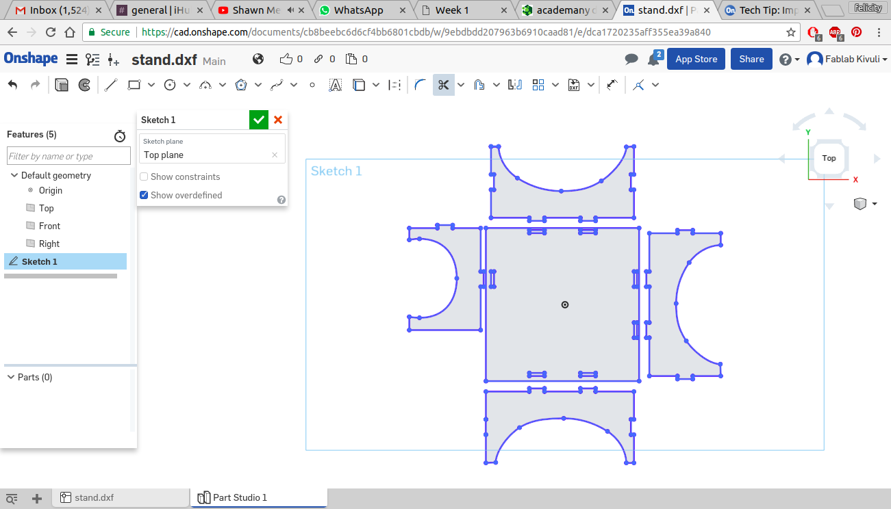
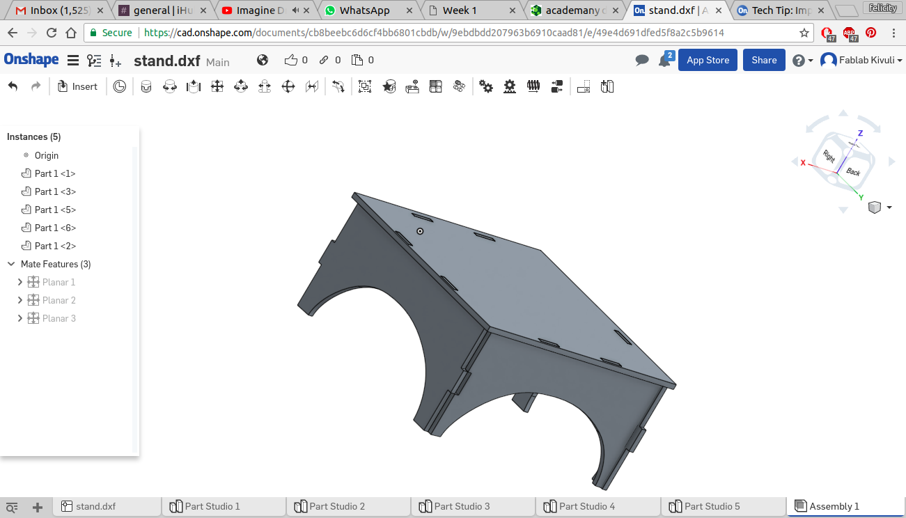
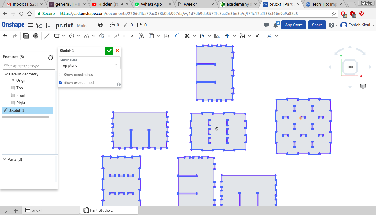
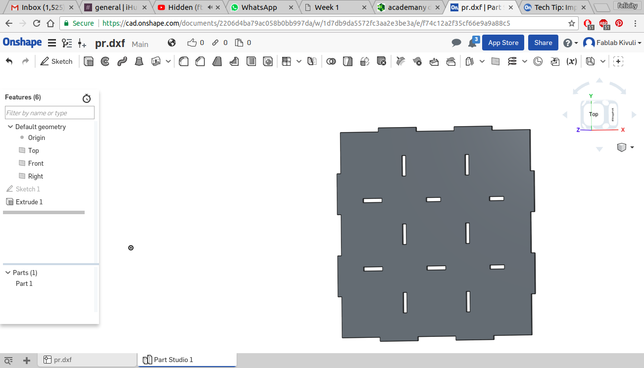
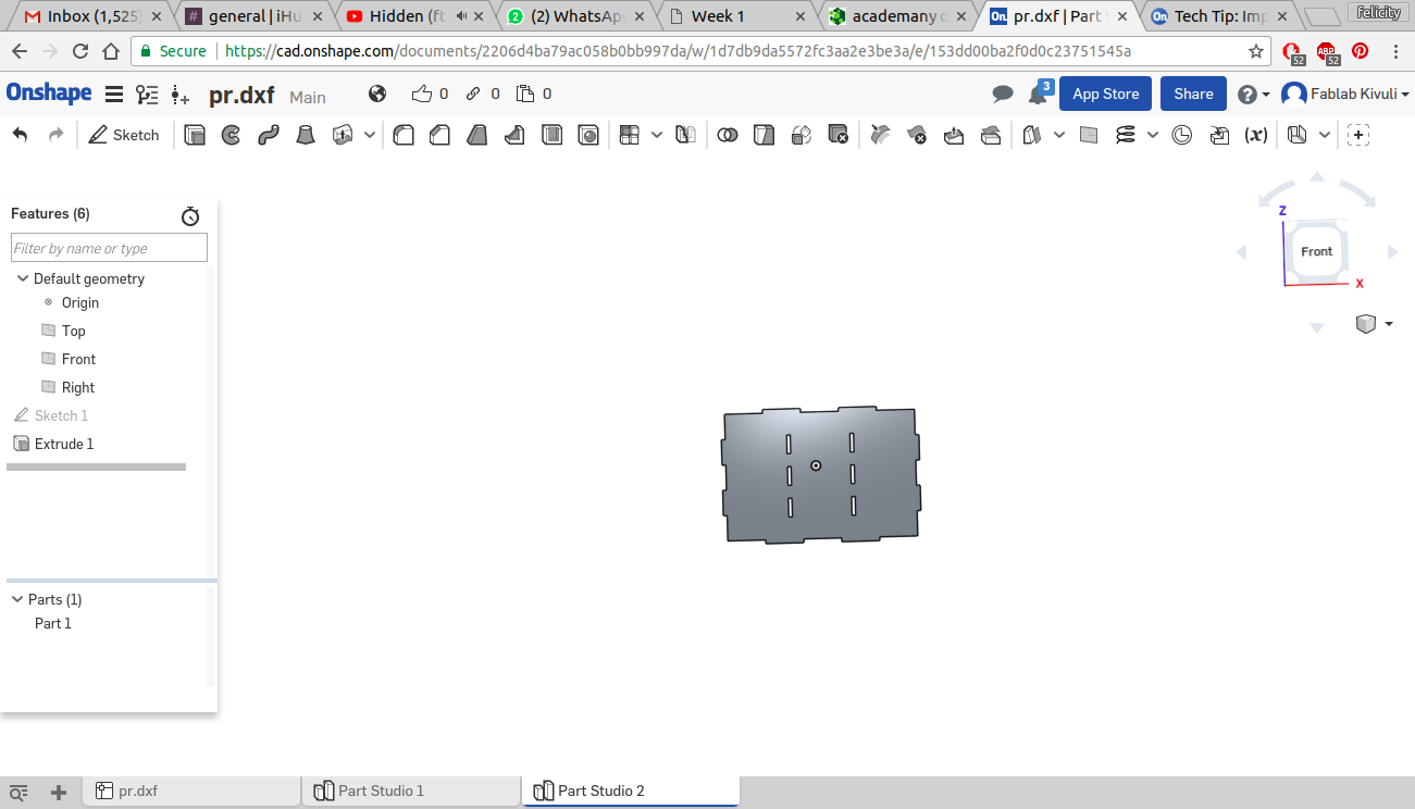
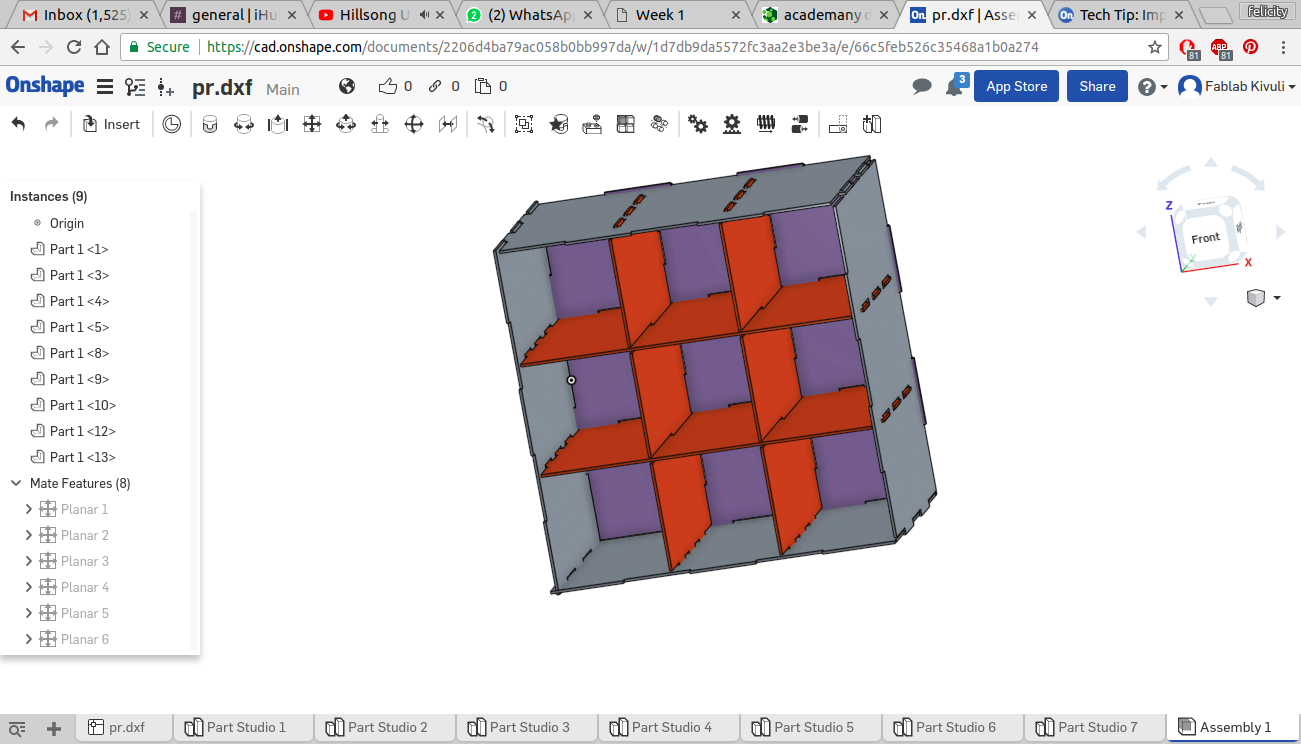
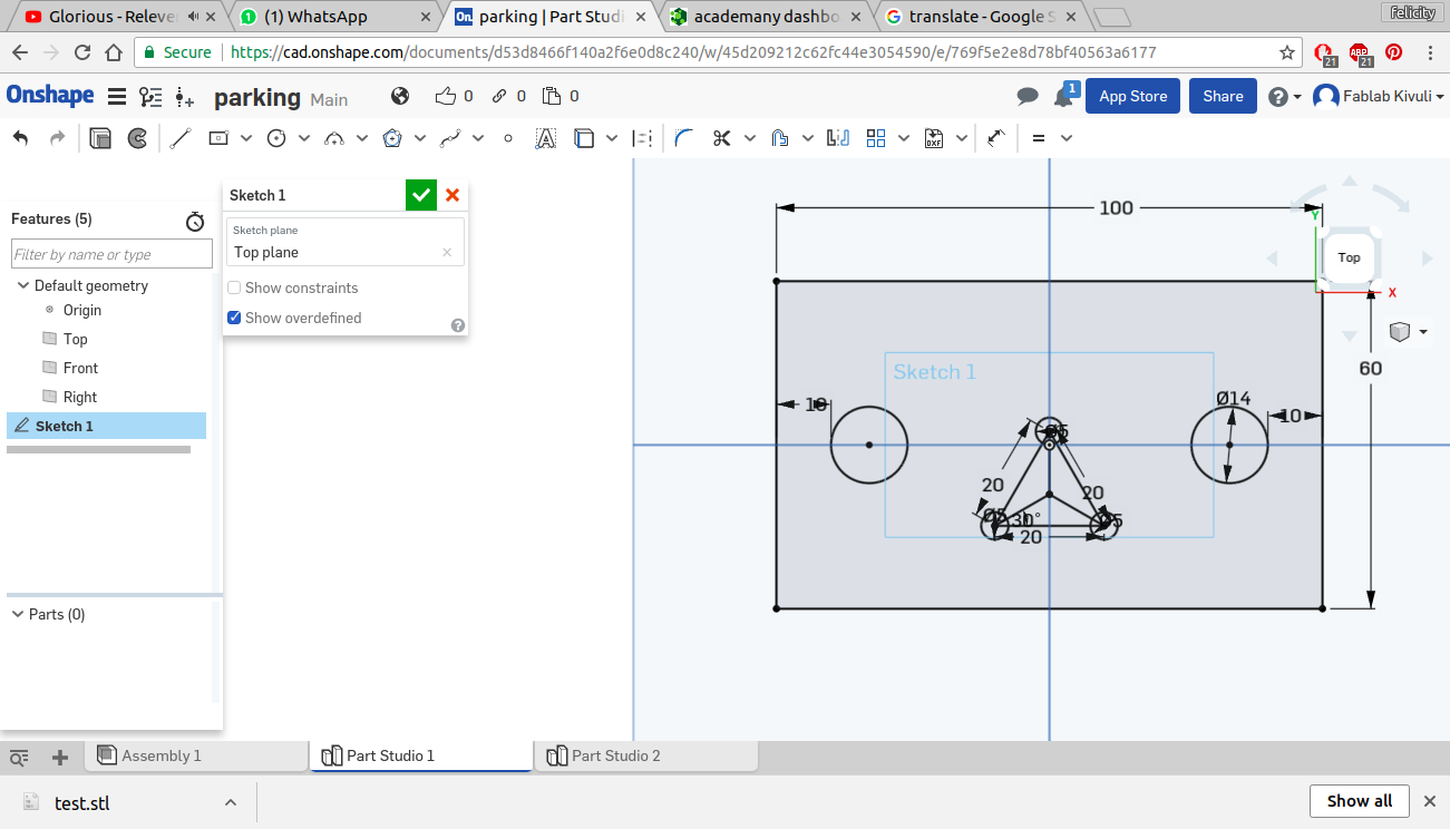
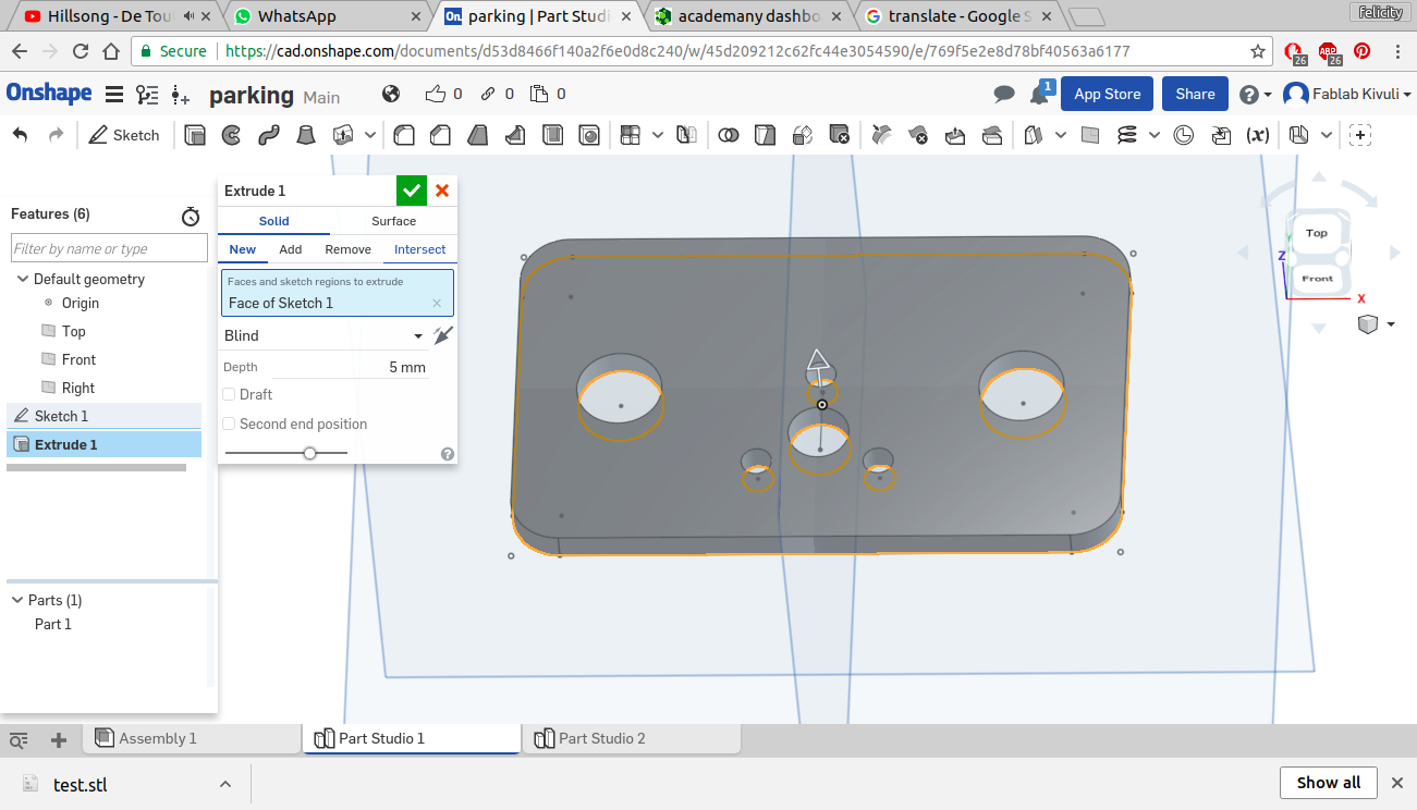
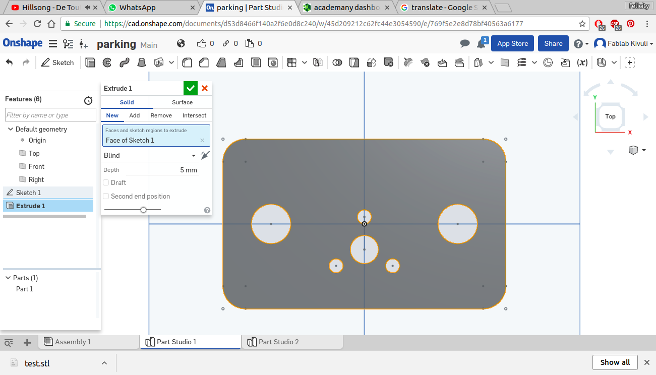
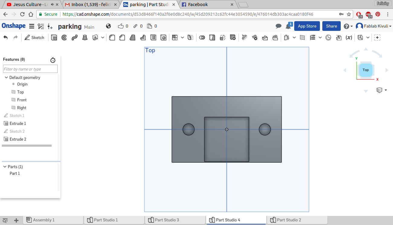
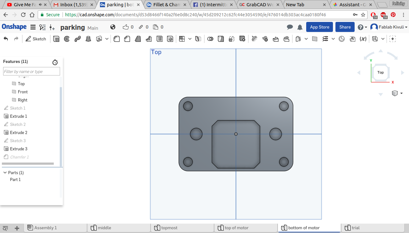
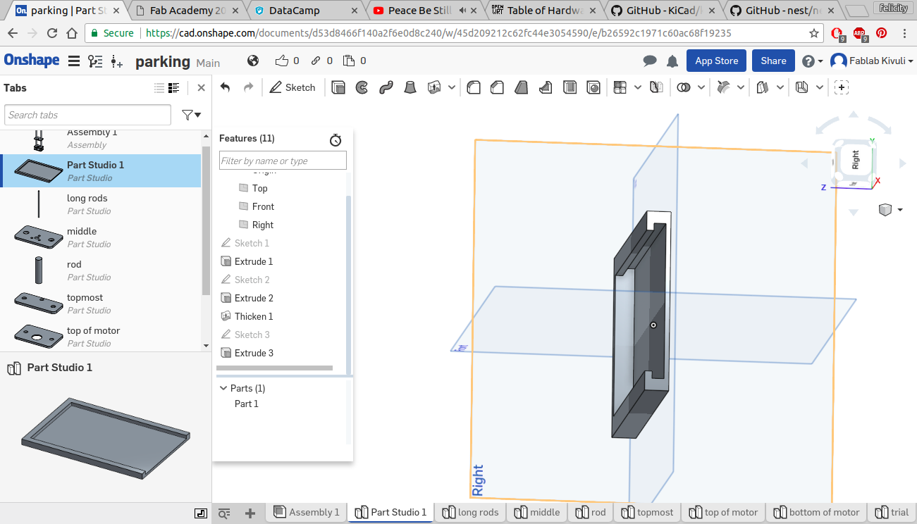
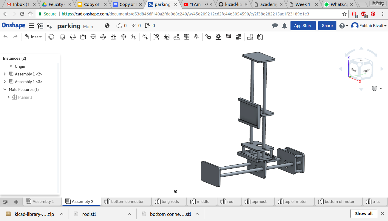
To transform this into a 3D model i sent the dxf files to onshape as seen below and gave it a thickness equivalent to that of the cardboard and assembled it in a part assembly. The cad design can be foundHere
importing dxf
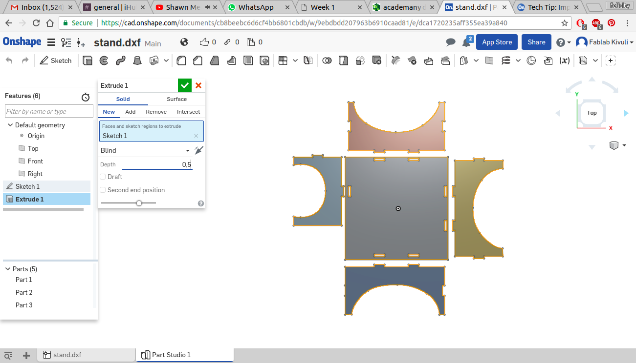
extruding
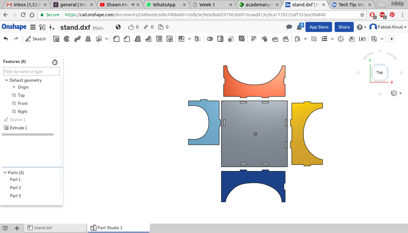
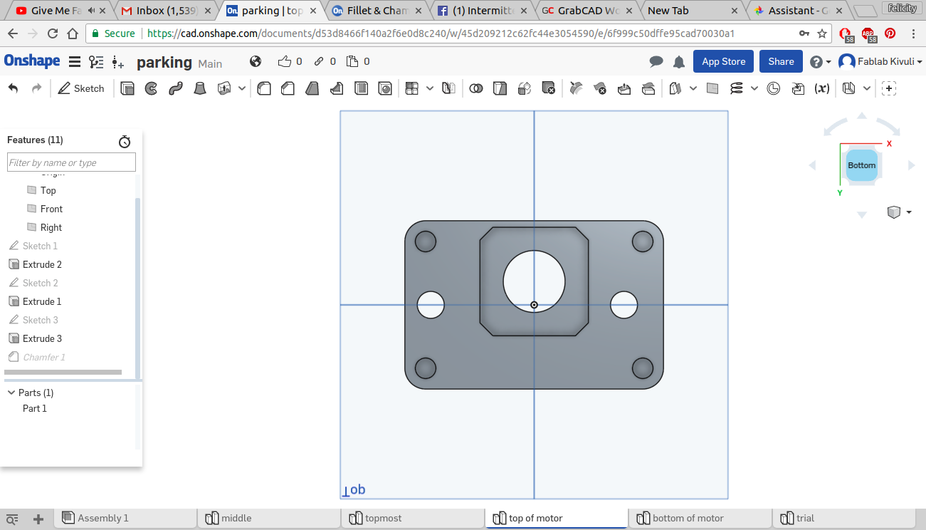
in 3D
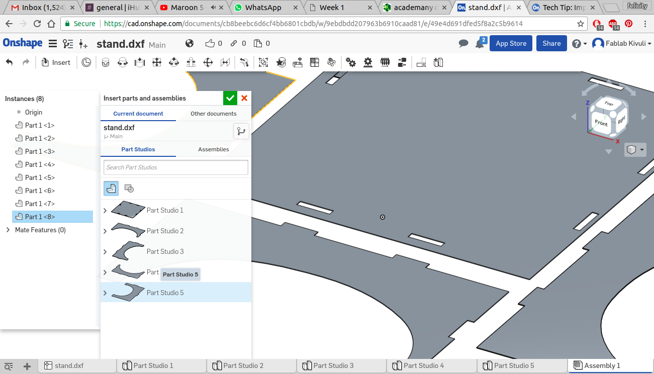
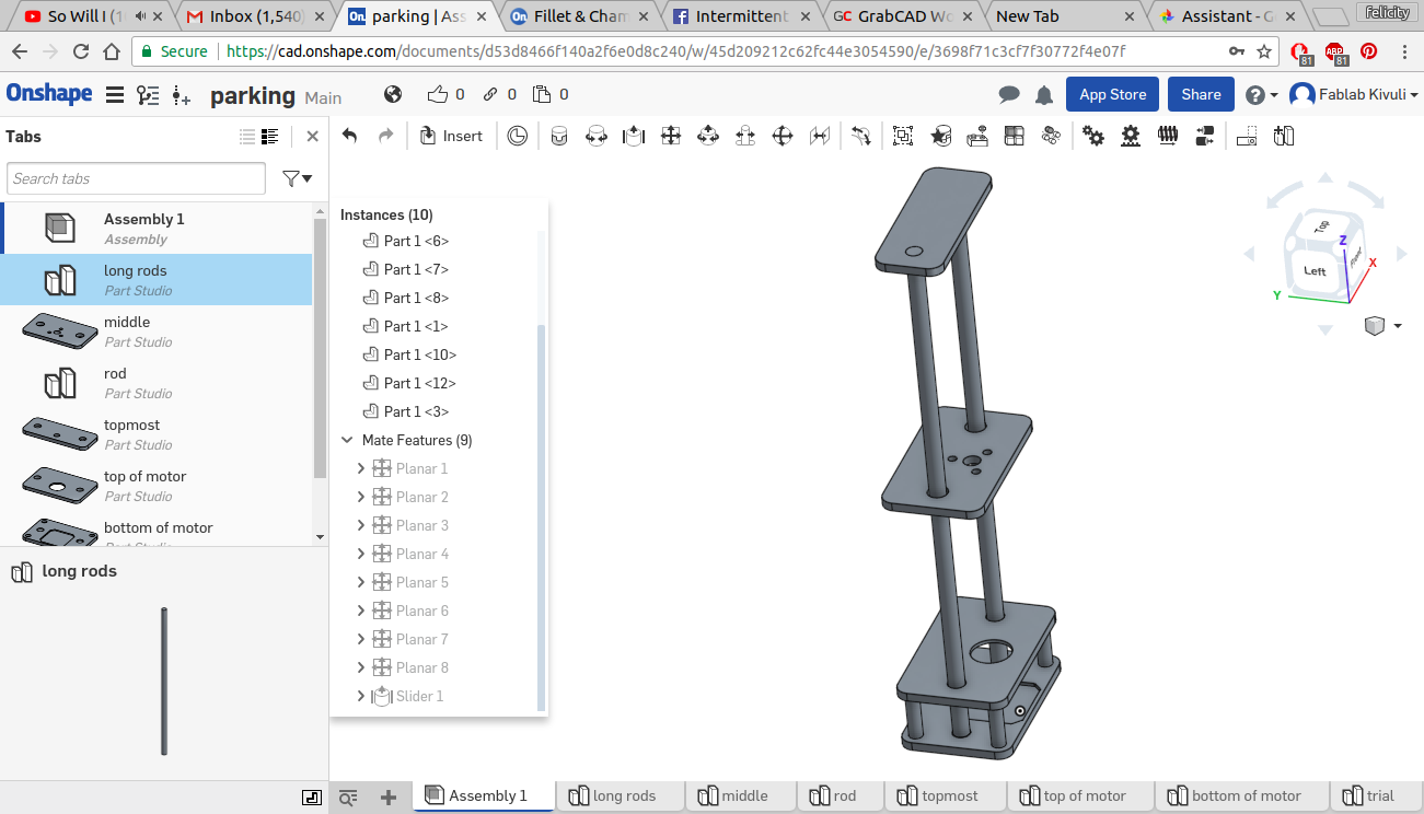
Rearranging and rotating parts
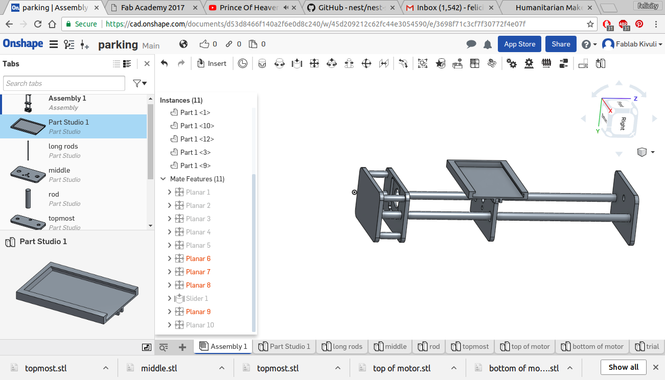
The assembly
model lot
<
import dxf into On shape
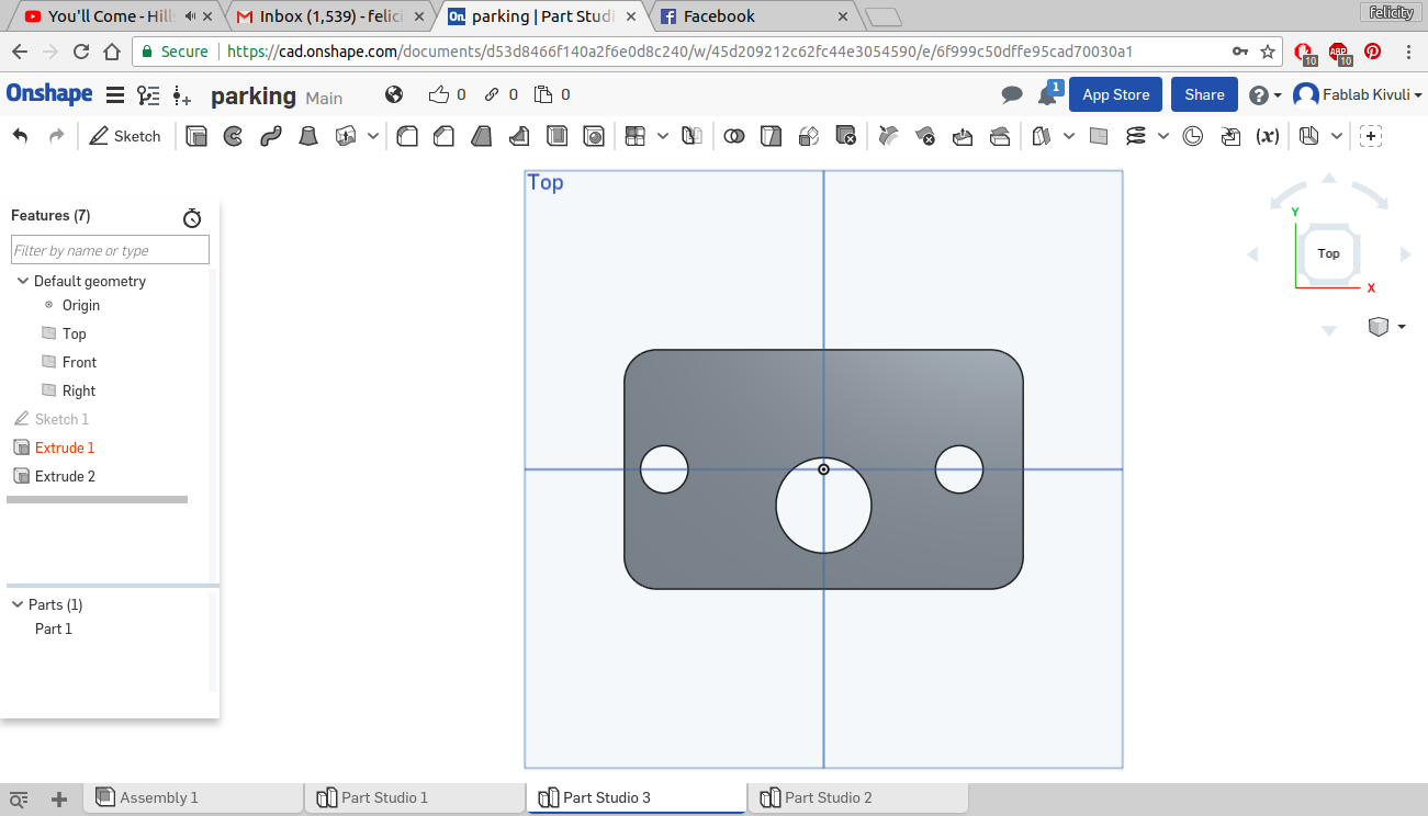
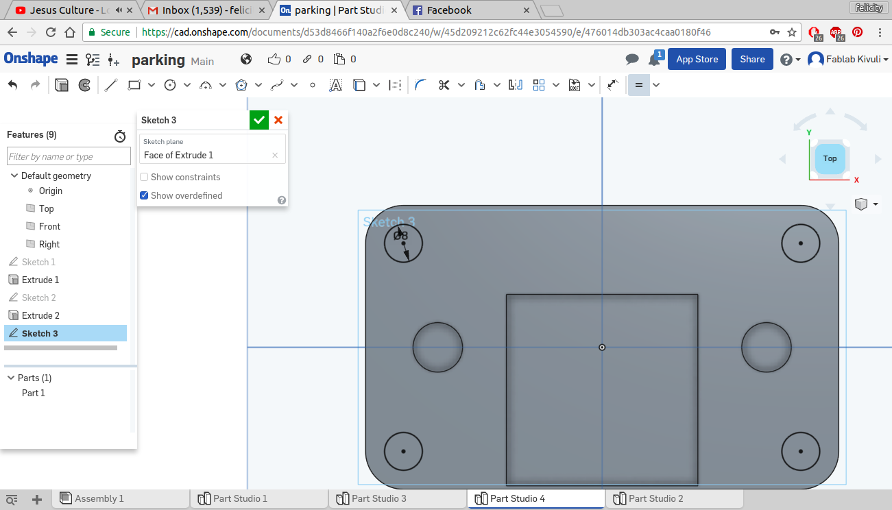
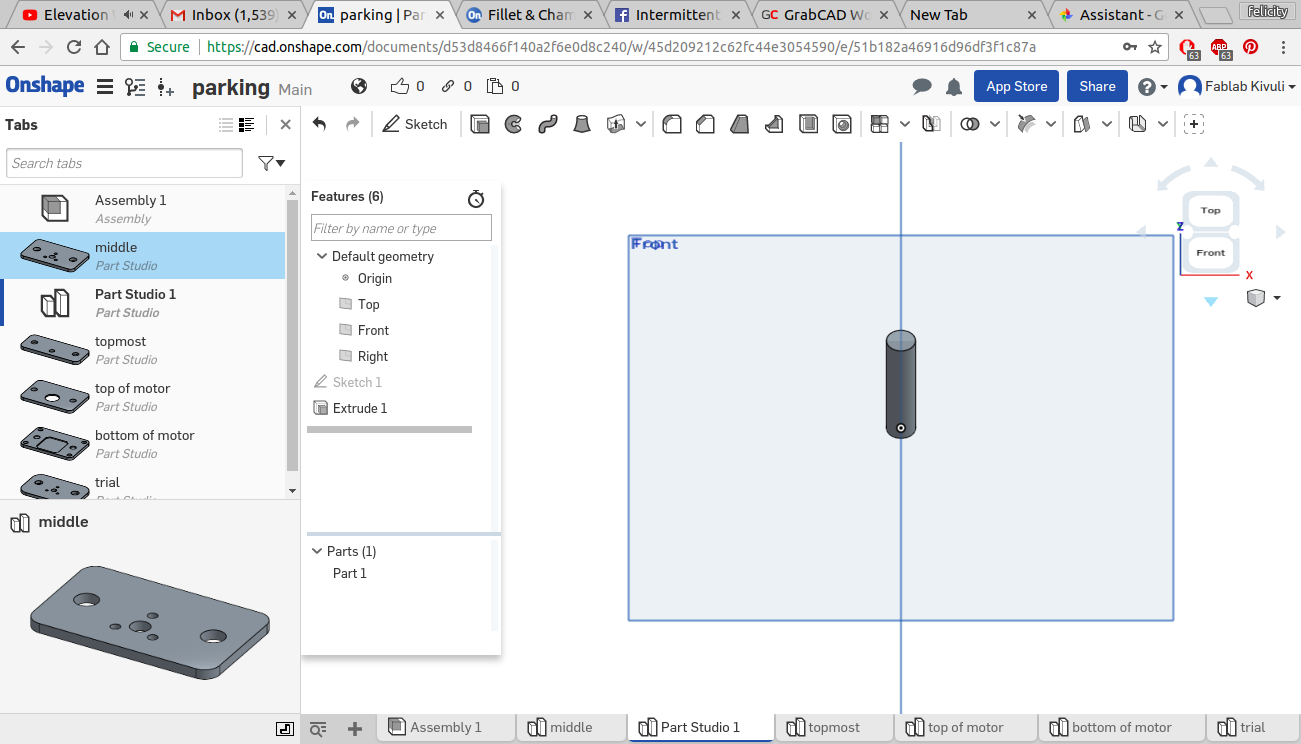
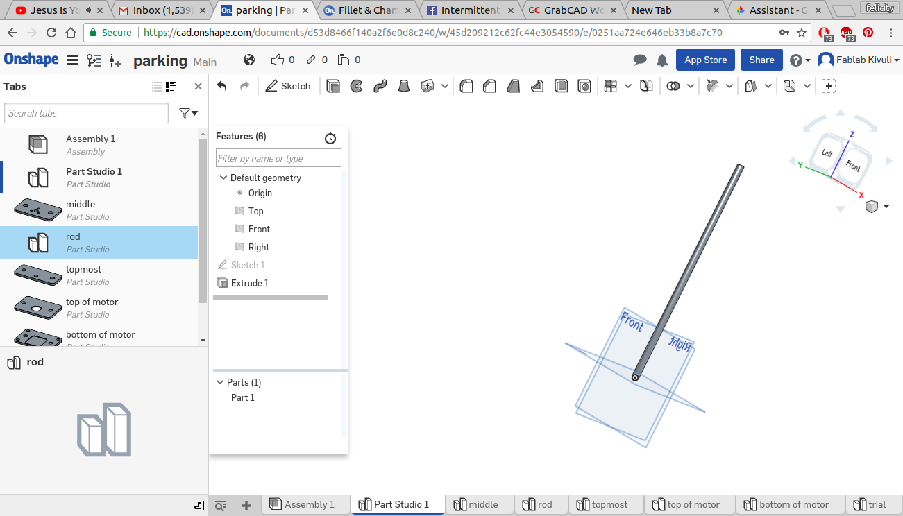
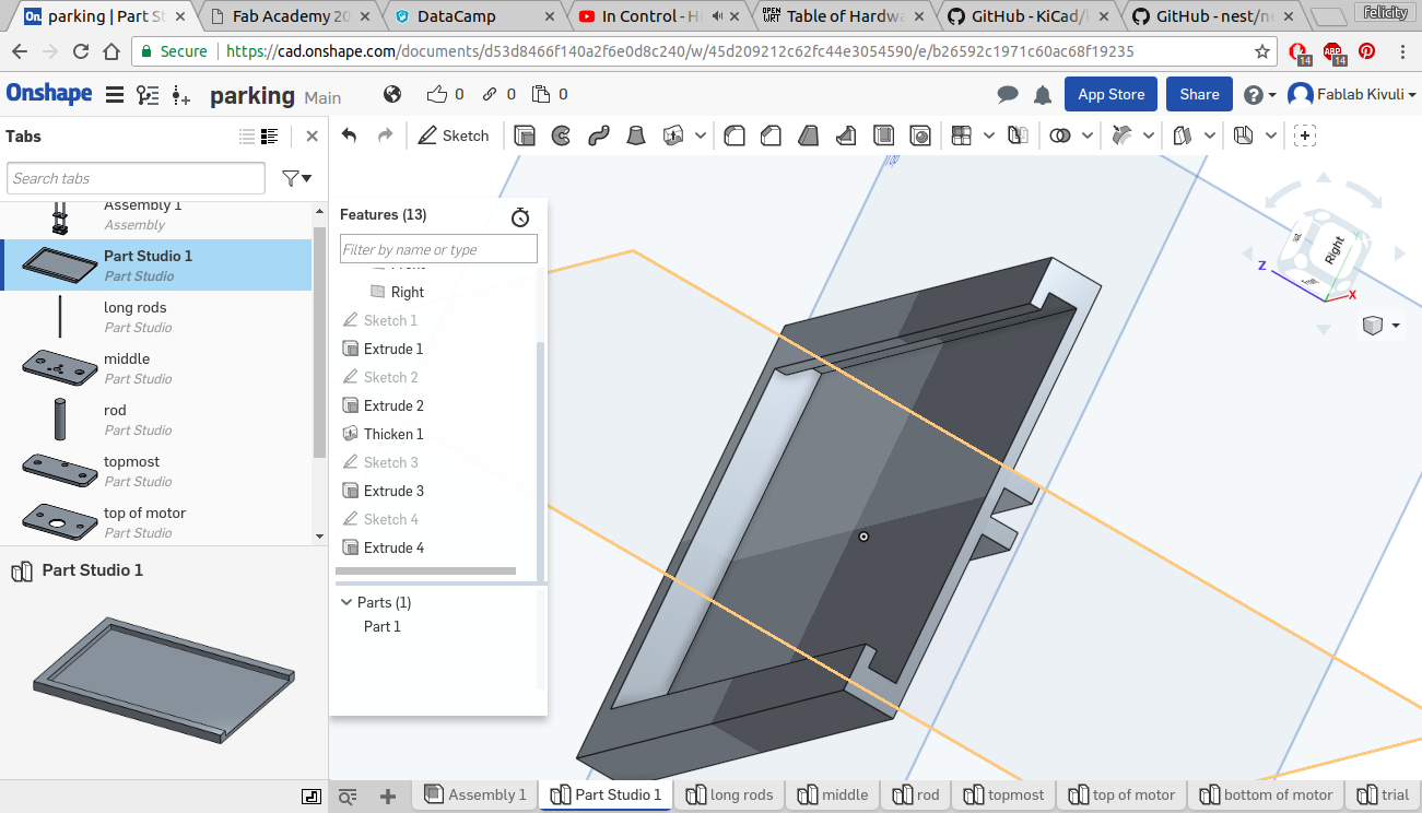
extruding the parts one at a time
<
second part
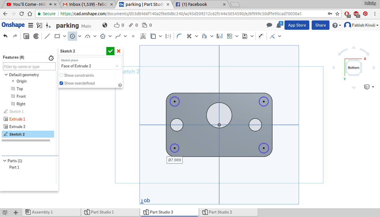
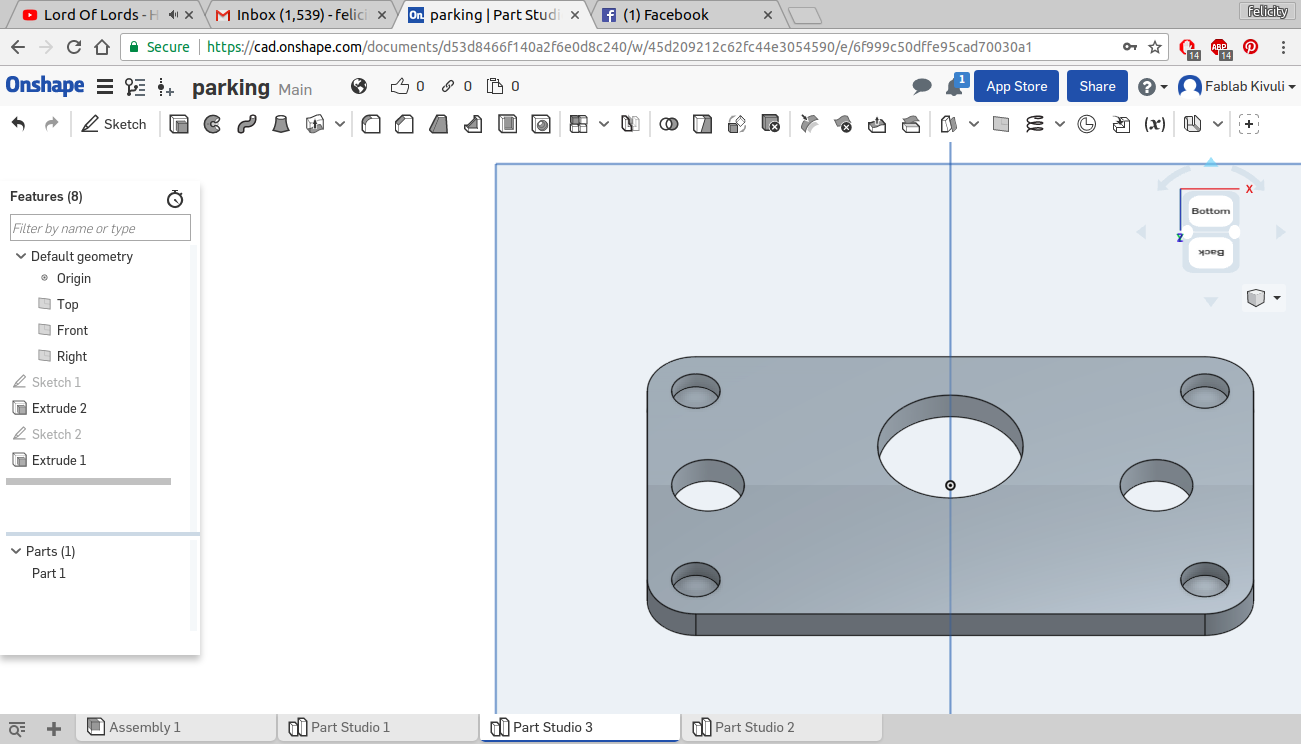
all the parts extruded
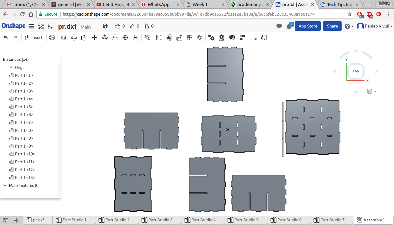
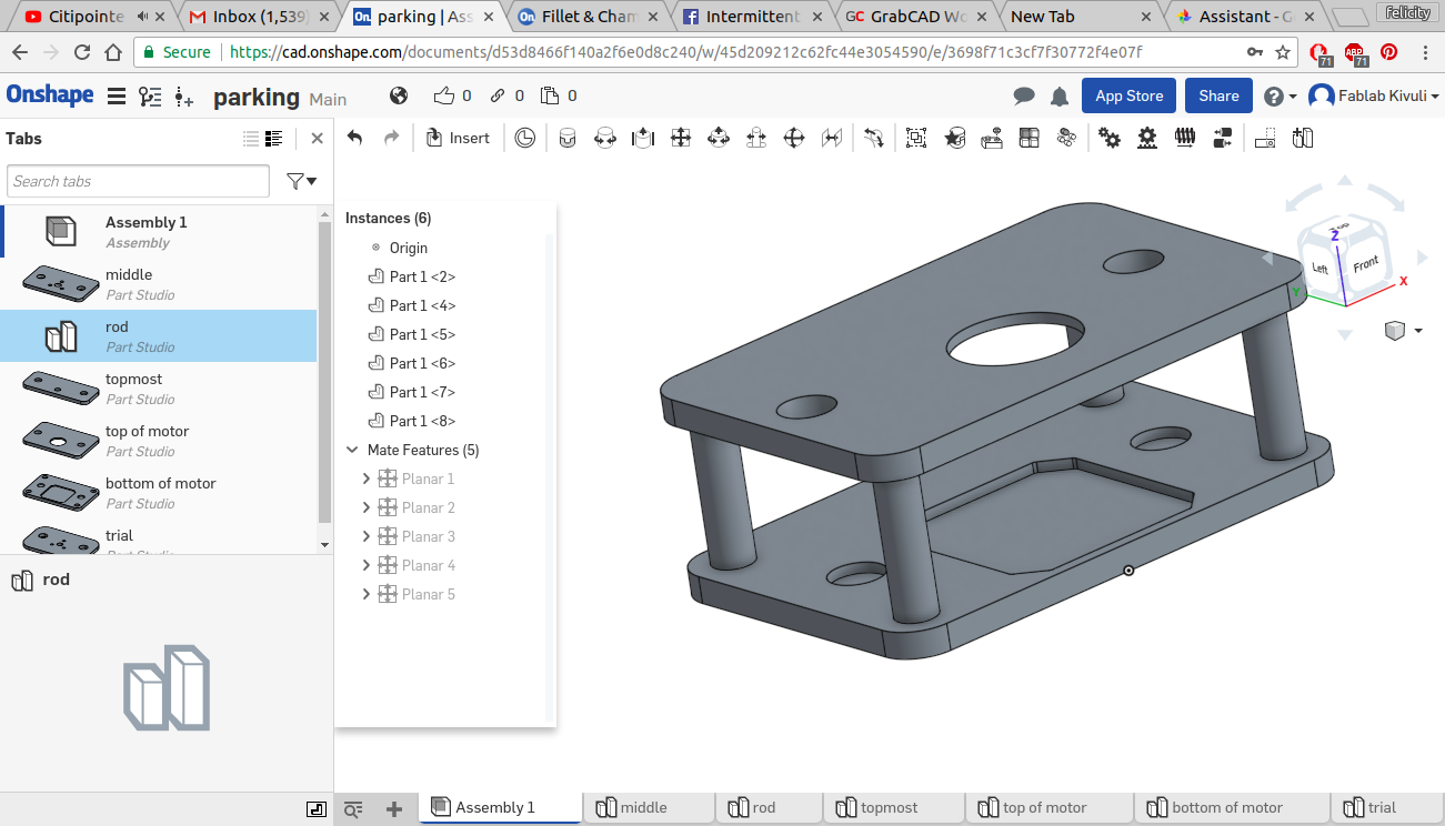
moving and rotating the parts
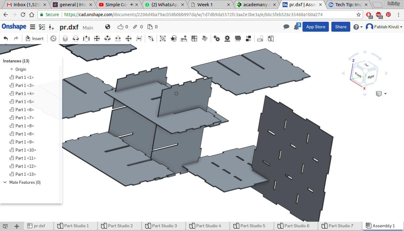
assembly using planar mates
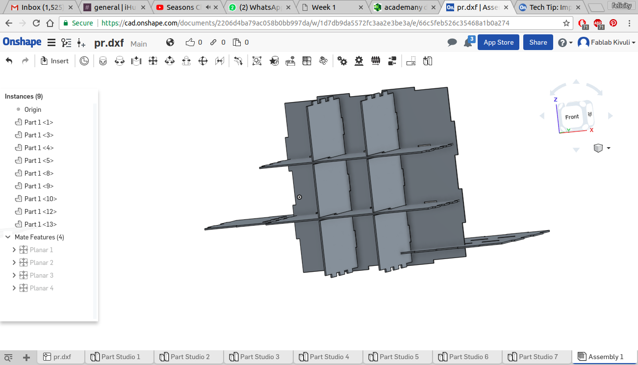
full assembly with appearance settings modified
The assembly can be found here
3d printed
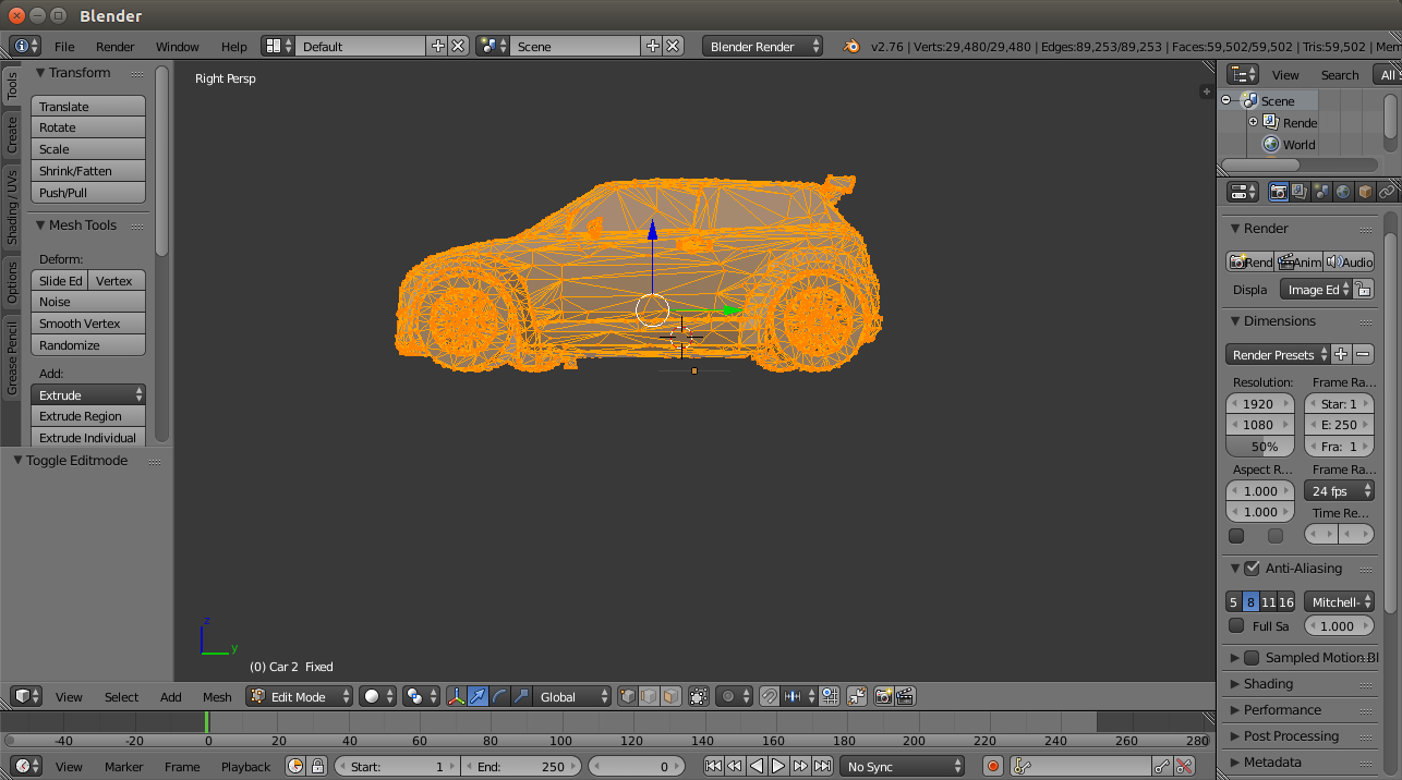
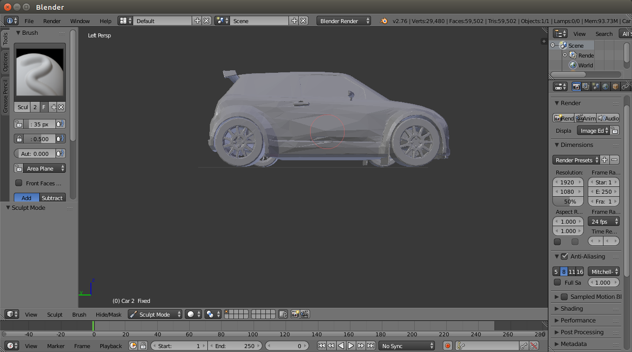
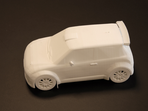
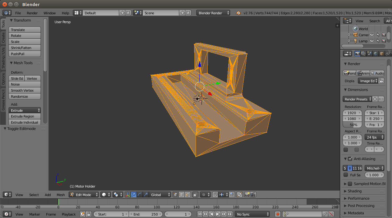
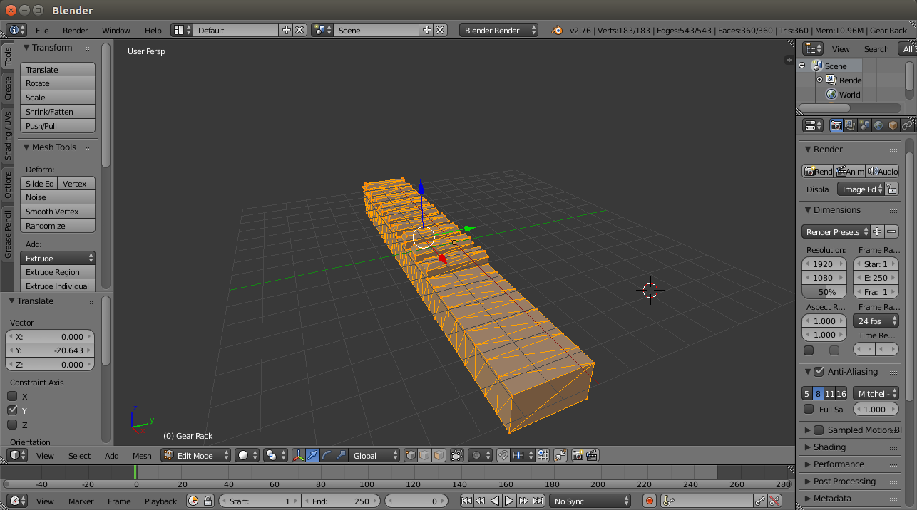
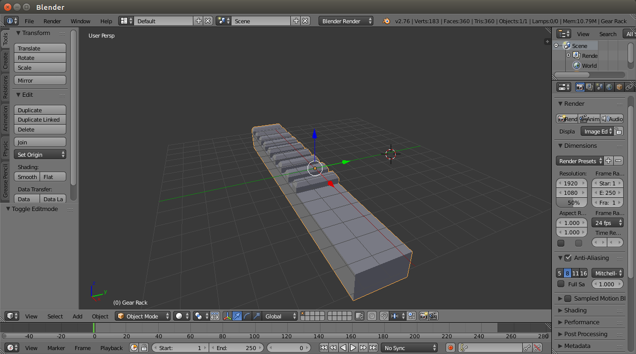
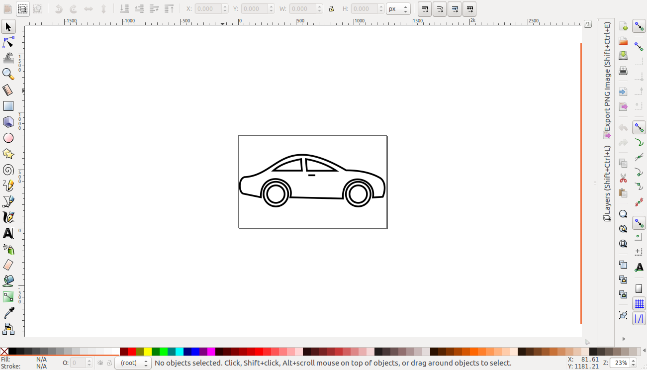
The 3D printed parts were a model car and a rack and pinion shown below. I used blender software to edit the different parts by importing them and toggling to edit mode. In this mode i could do various modifications in size to fit my design. For the car, i resized it to fit the slots ot the model car parking slot. For the servo holder, rack and pinion i made it smaller and adjusted the hole fitting the servo to be the same size as mine. The models are found in the link 1 and this link 2
car in blender(mesh editing)
car (object mode)
car
Servo holder
rack(mesh)
rack
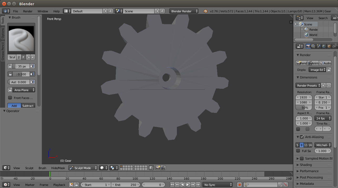
Pinion gear
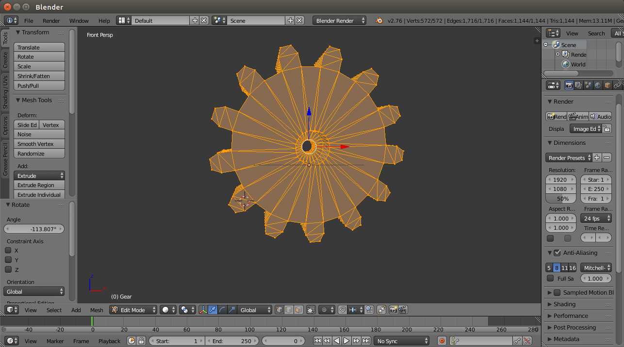
pinion gear
The electronics
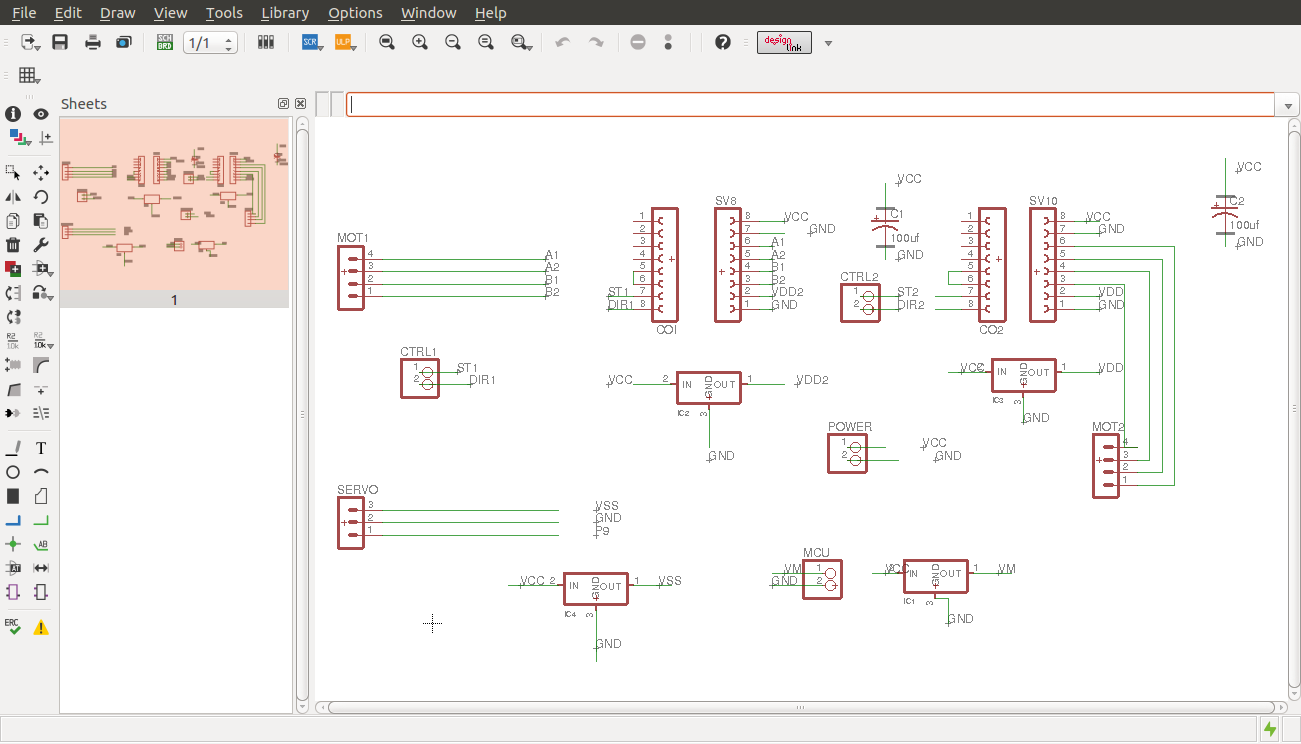
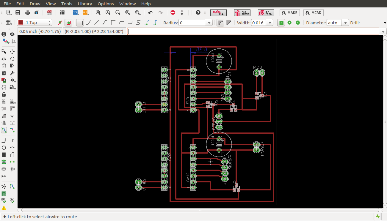
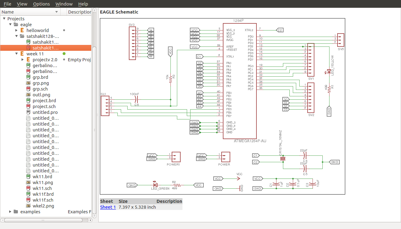
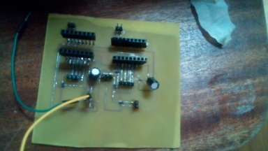
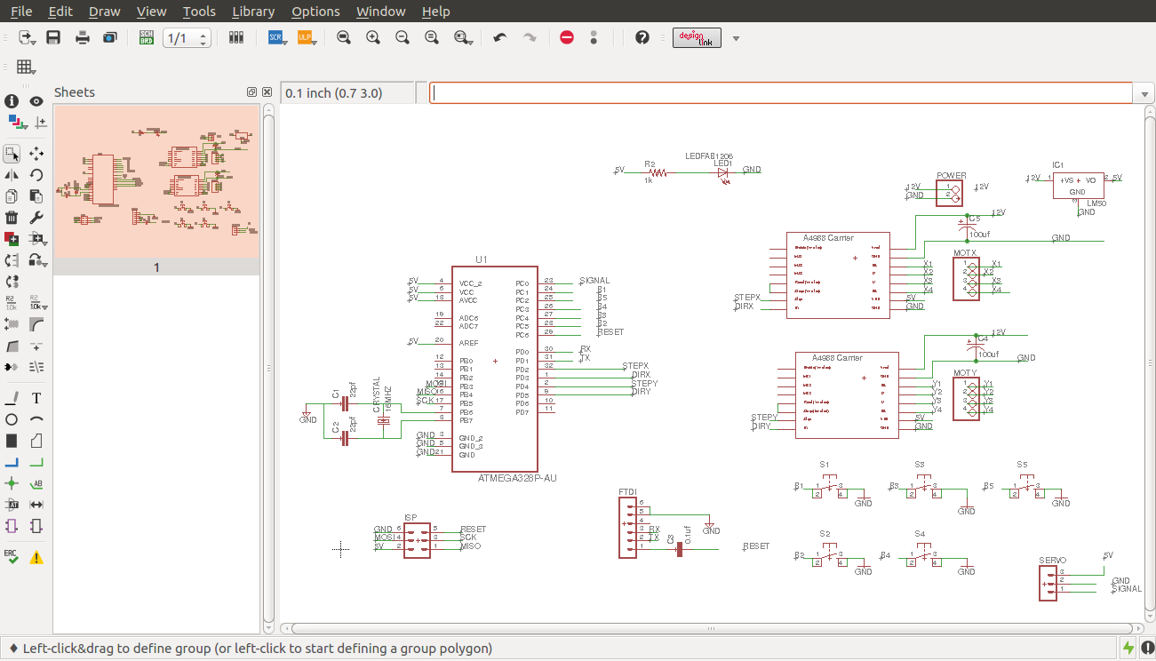
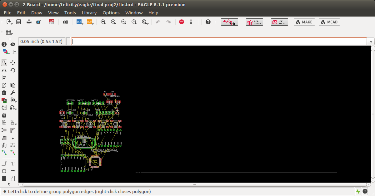
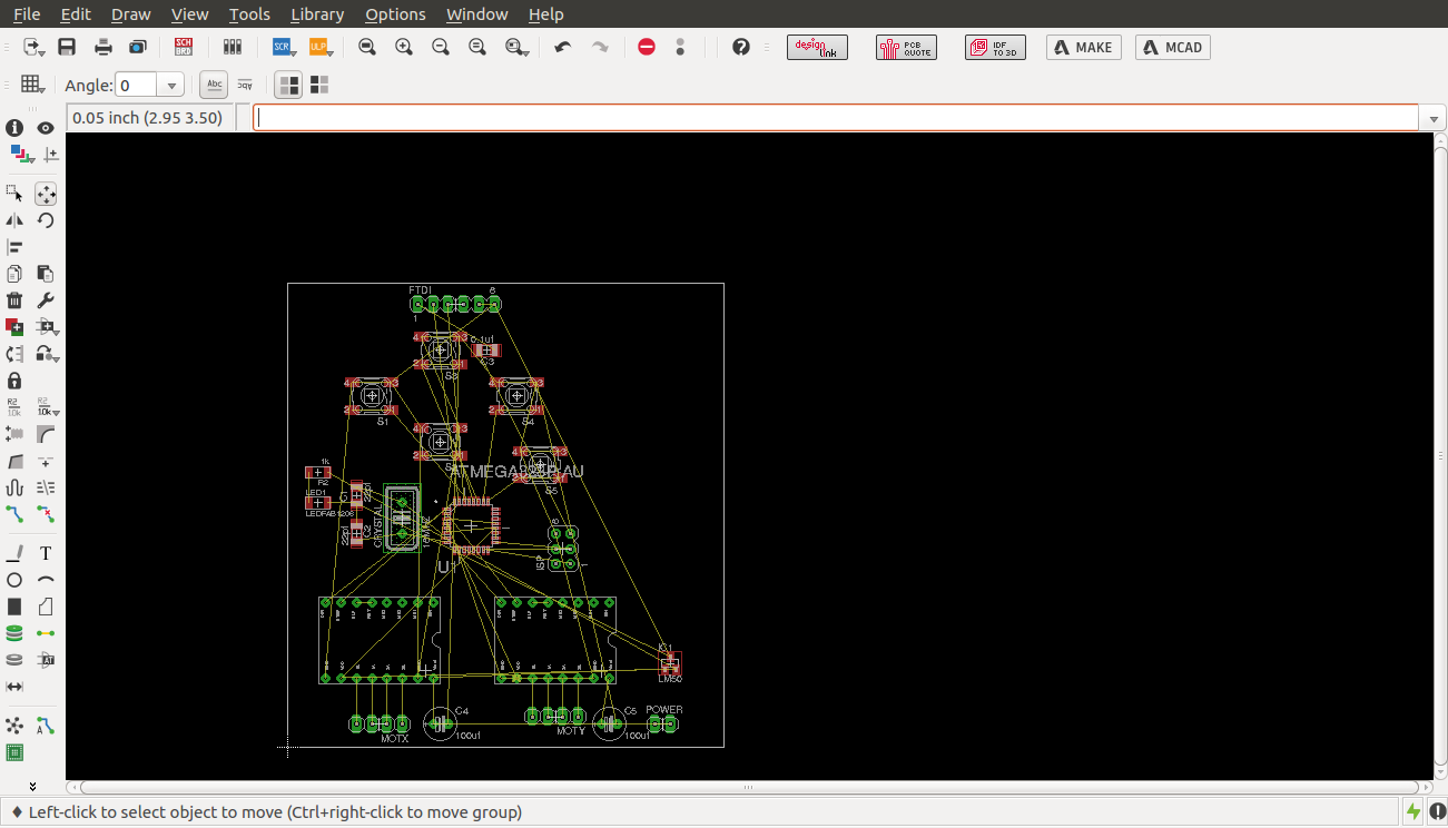
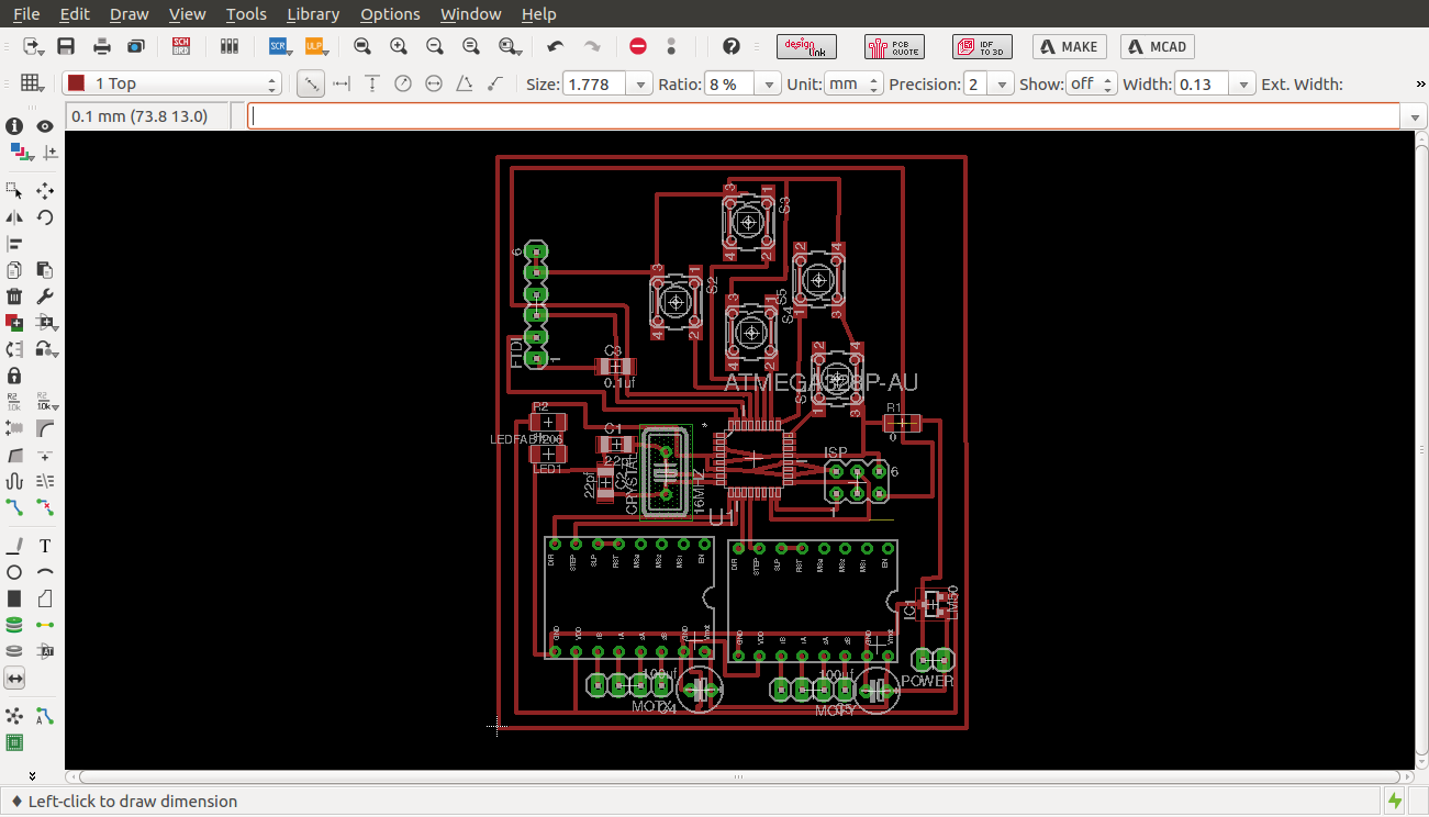
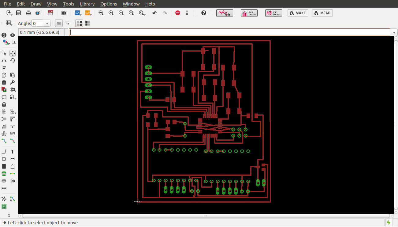
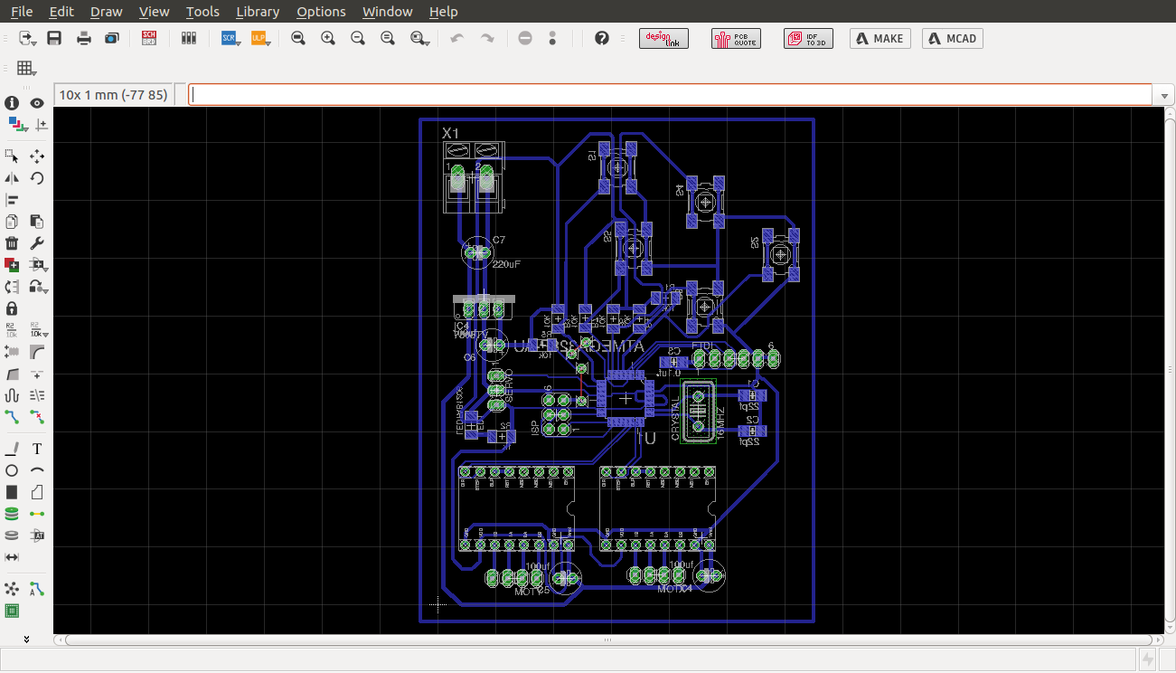
For the circuitry i fabricated control board using atmega 1284 and designed a separate board for power regulation for both the microcontroller board and the pololu motor drivers. the motors run using 12V whereas the rest of the board uses 5v. Circuit design was done by using Eagle software.
Eagle schematic
Eagle board
controller board schematic
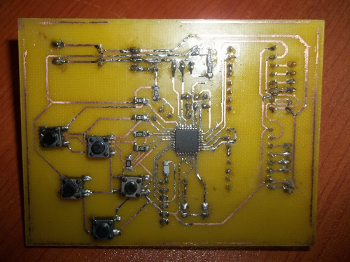
controller board

board
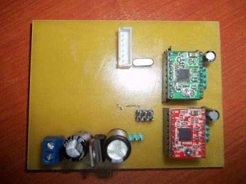
motor controller board
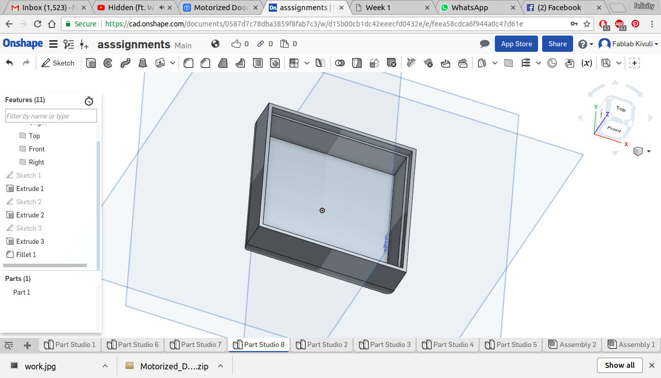
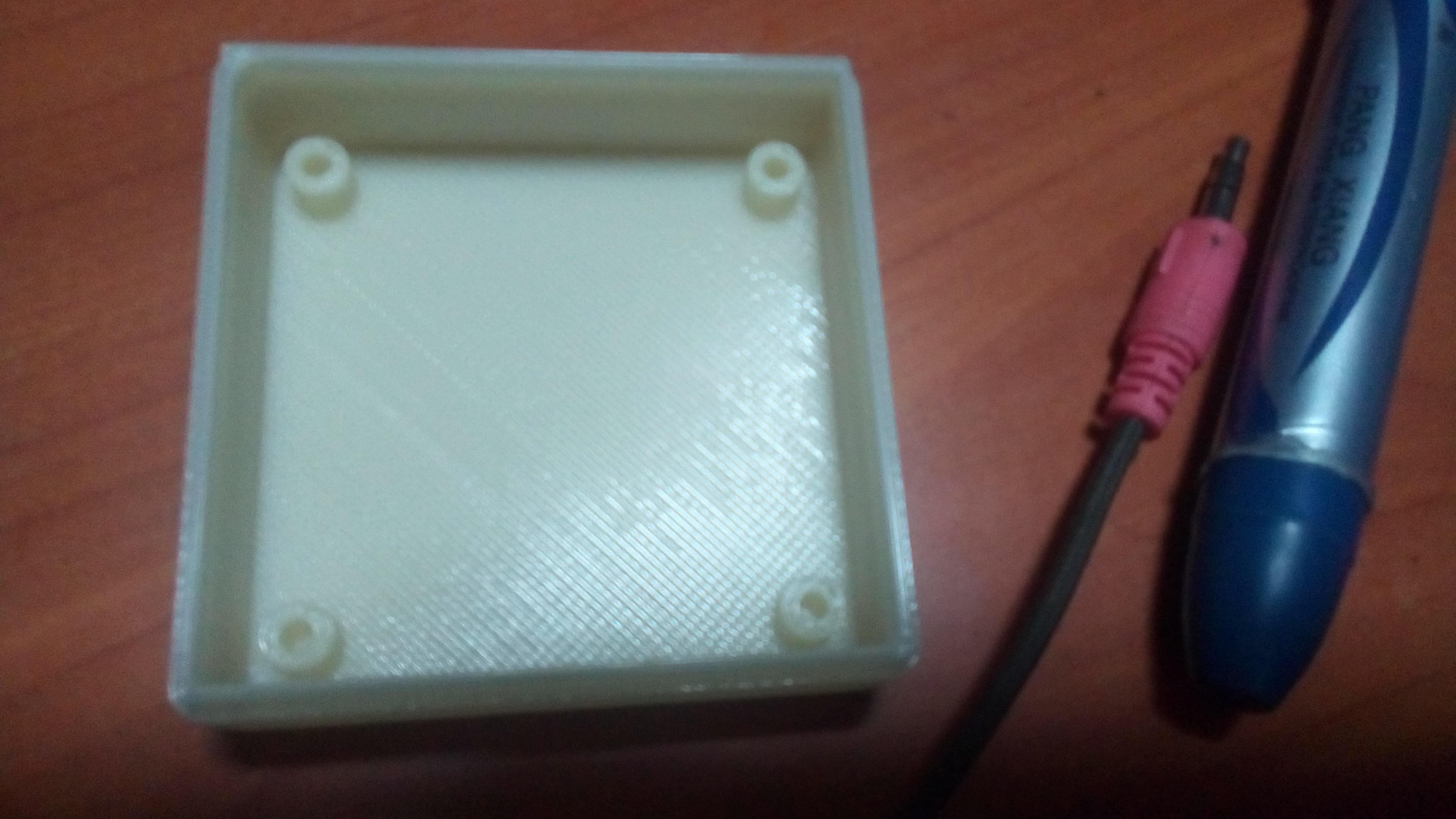
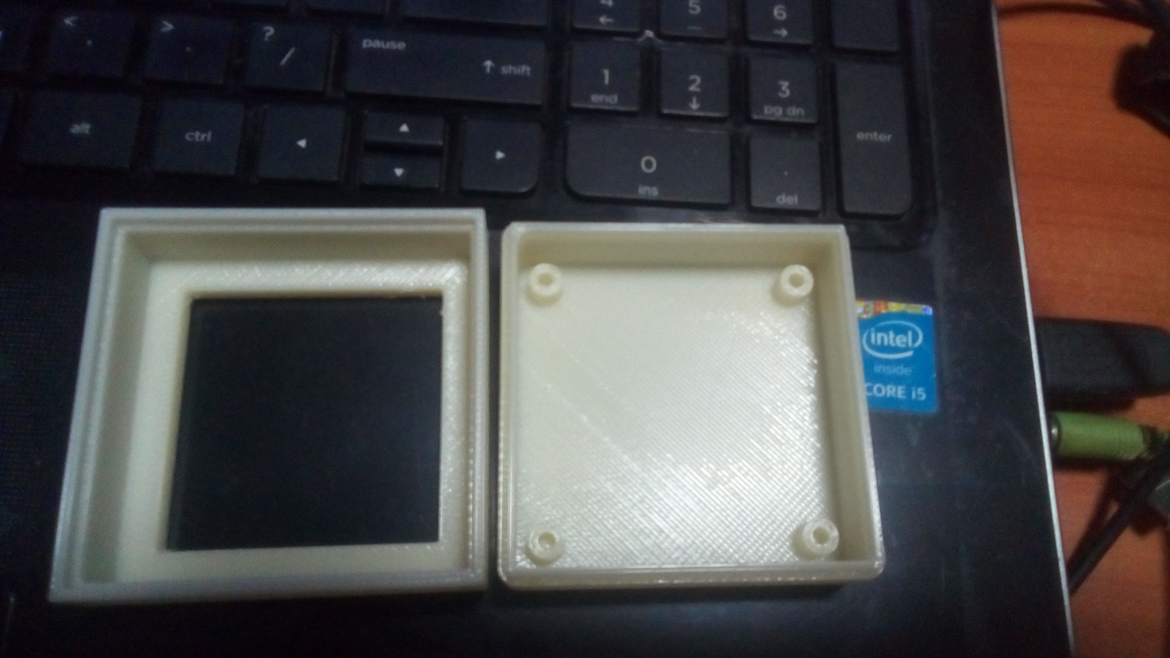
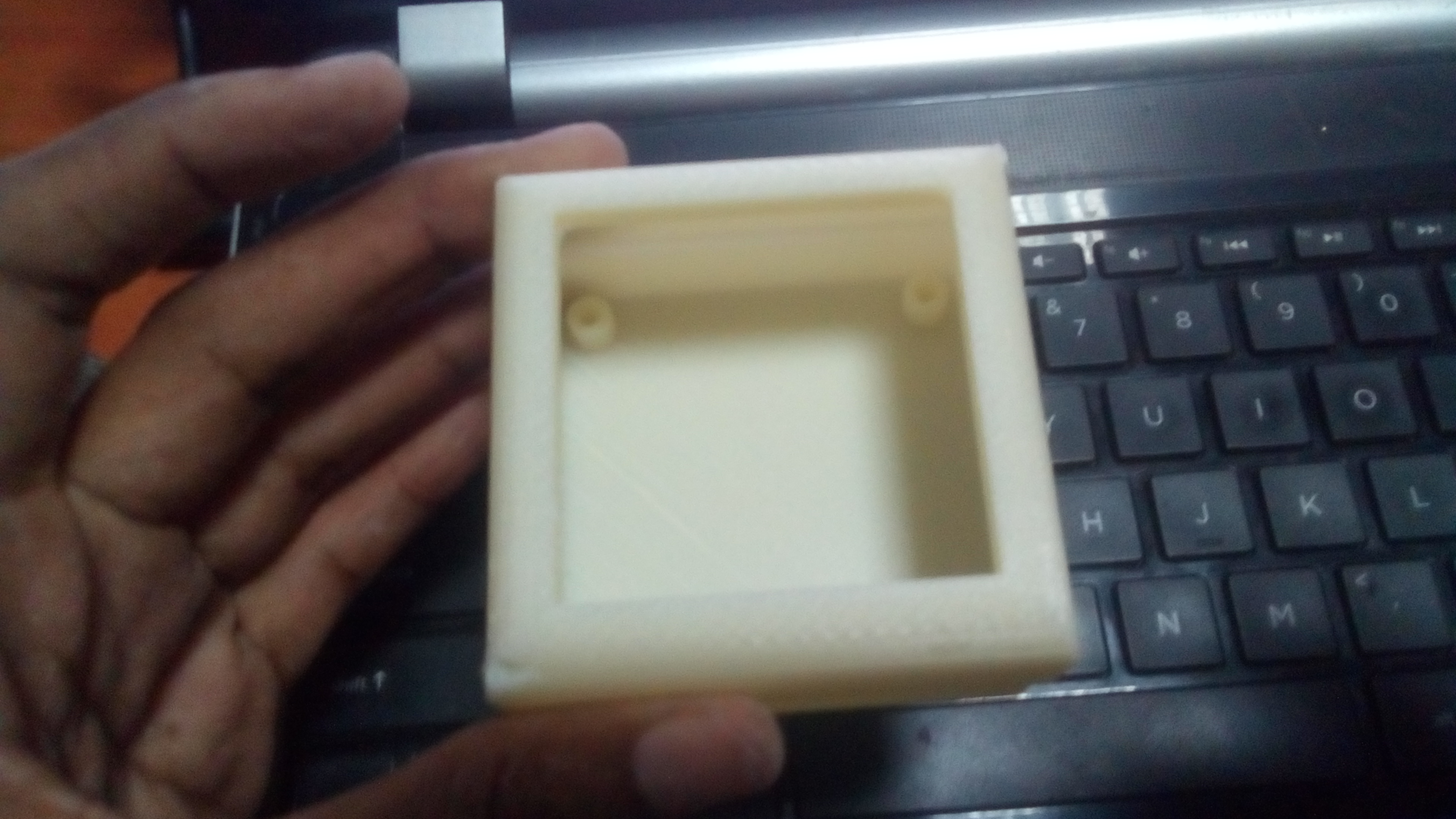
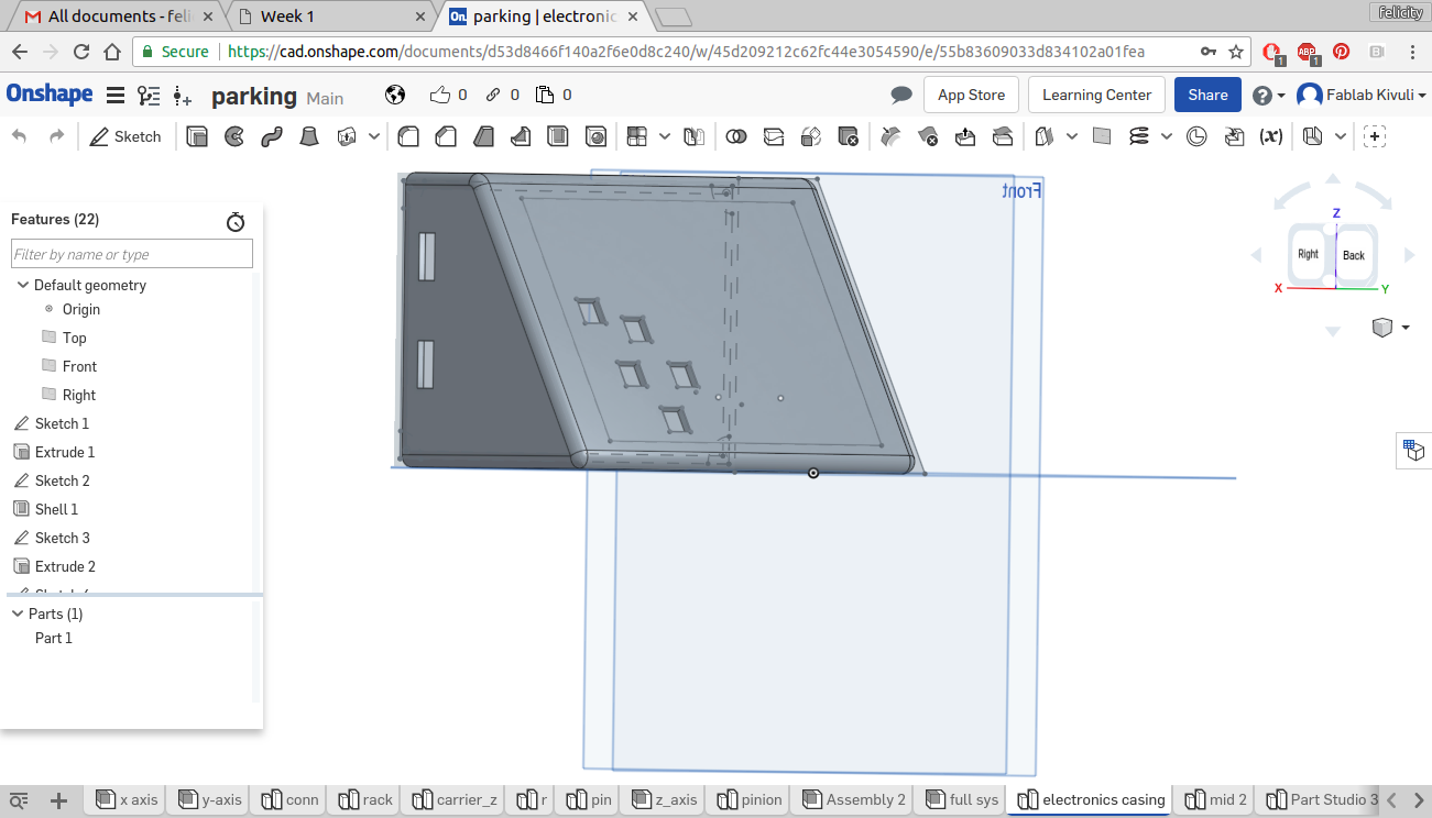
Casing for electronics
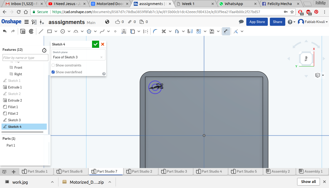
I decided to then design a casing for the electronics. I started with making the botttom part with nternal fixing holes for screwing the board onto.
sketch
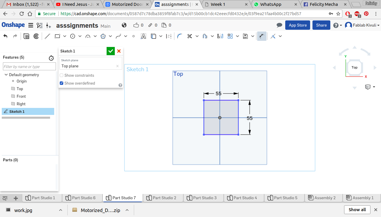
sketch
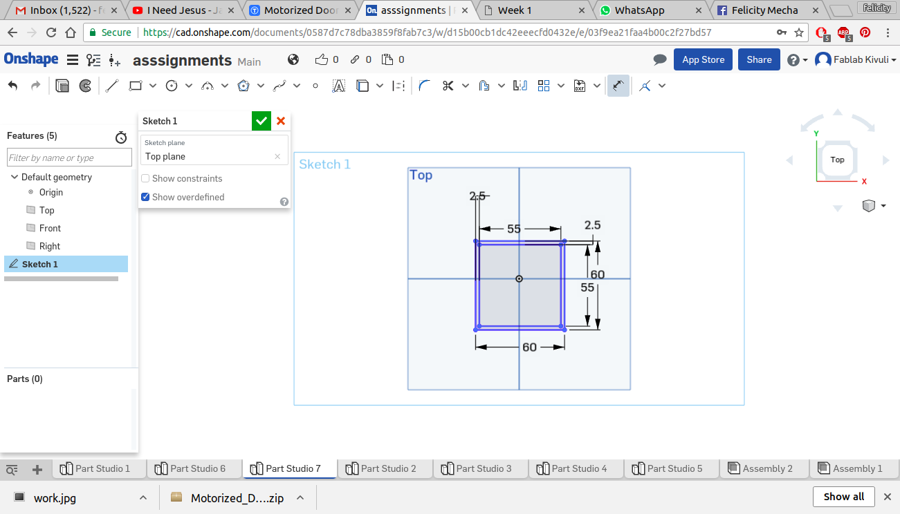
extrude and sketch of fixing holes
extruding the sketches
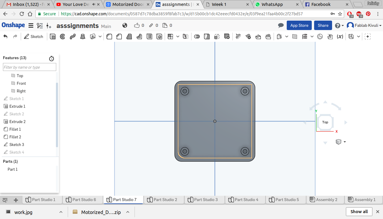
model with fixing holes
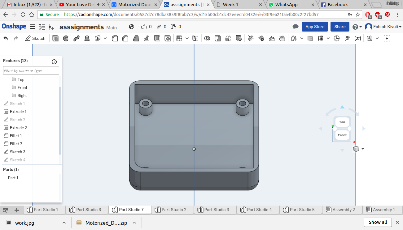
complete with fixing holes
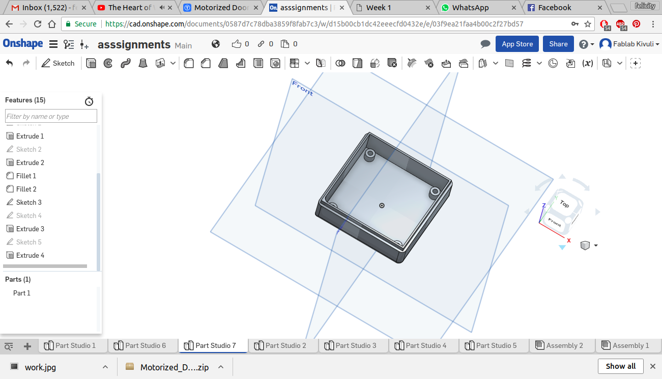
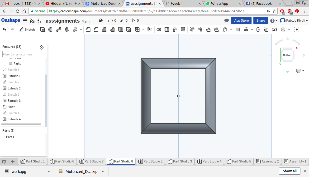
I Then made the top cover and gave it an open top so that the jumper wires can move out of it
Top
Top
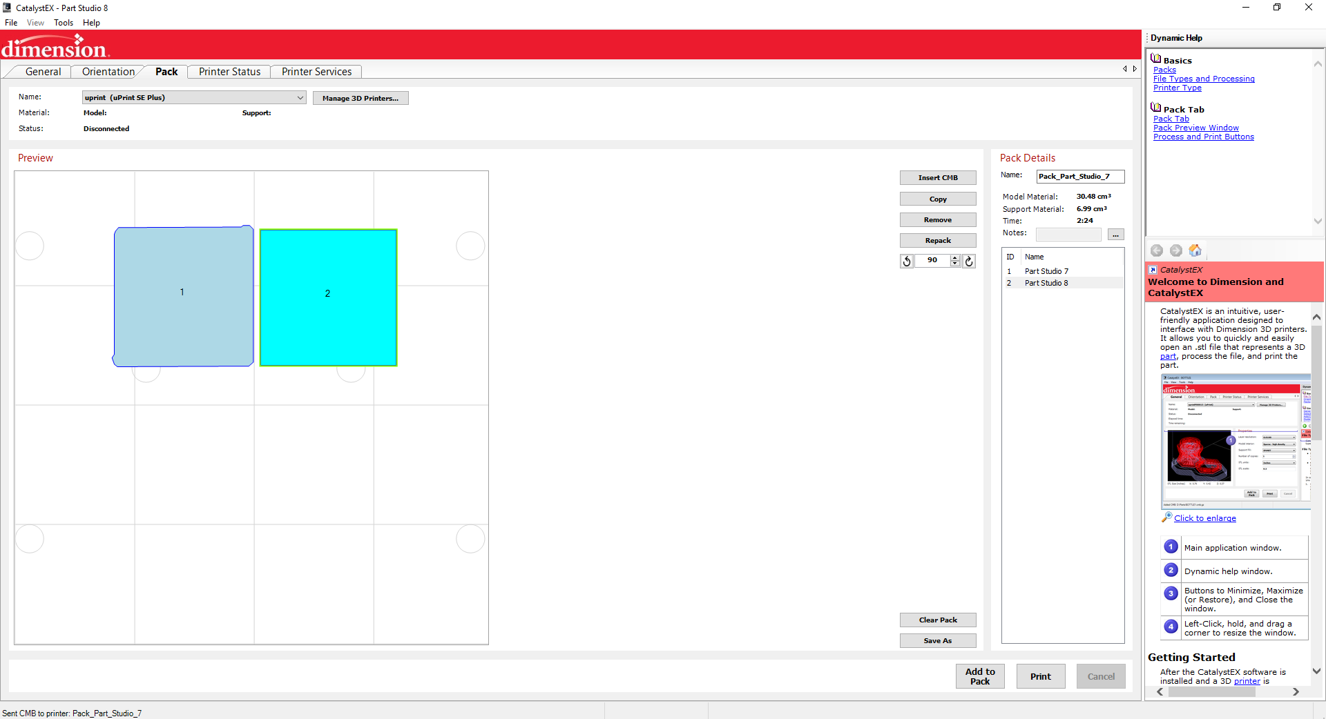
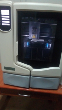
I then went on to print it using the uprint se plus through the user interface called Dimension.
sending to printer
in the printer
The top font
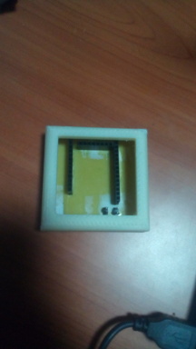
The top back
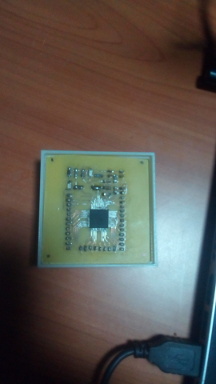
drilling fixing holes on the board
The bottom
both pieces
putting it together
Assembled
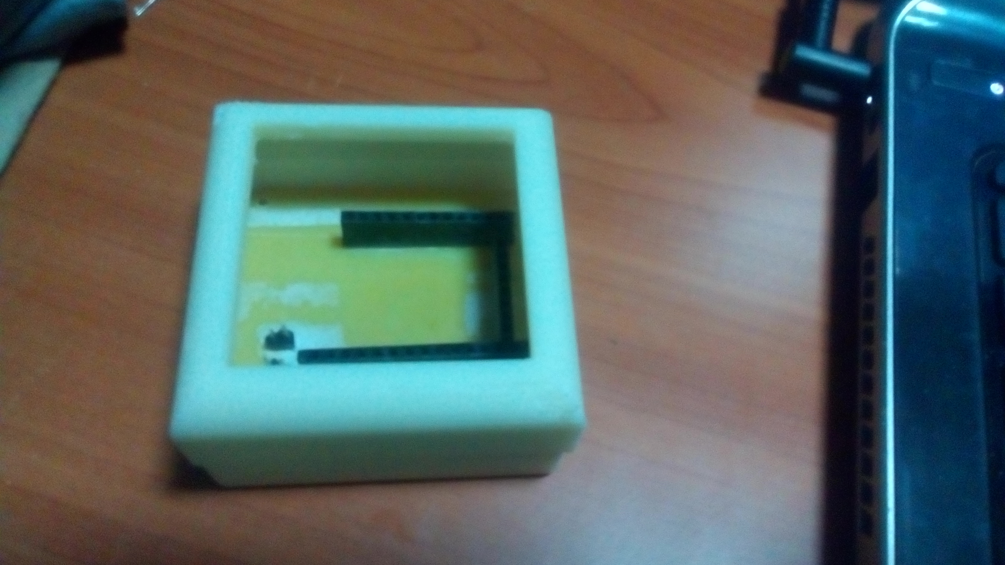
with the board inside
Downloads
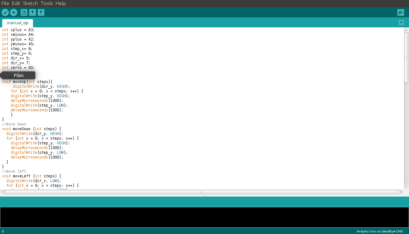
Programming
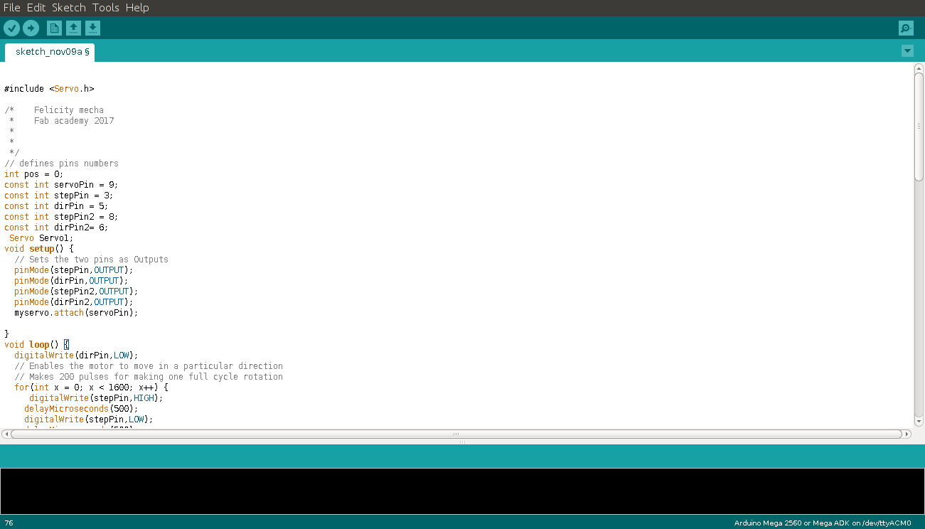
The program uploaded was programmed on arduino IDE. The program controls the movement of the motors. it runs a loop that first moves the first(x axis) motor for 8 revolution in the forward direction . The code that controls this movement is shown below.
digitalWrite(dirPin,LOW);
  // Enables the motor to move in a particular direction
  //  200 pulses are for making one full cycle rotation
  for(int x = 0; x < 1600; x++) {
     digitalWrite(stepPin,HIGH);
    delayMicroseconds(500);
    digitalWrite(stepPin,LOW);
    delayMicroseconds(500);
The second motor(y-axis) is then moved upwards by the same amount of revolutions. This is done by setting the direction pin to high. This is done with a similar code snippet.
 digitalWrite(dirPin2,HIGH);
  for(int x = 0; x < 1600; x++) {
     digitalWrite(stepPin2,HIGH);
    delayMicroseconds(500);
    digitalWrite(stepPin2,LOW);
    delayMicroseconds(500);
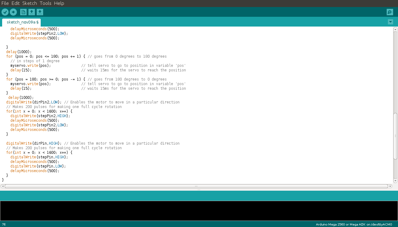
When at the top, the servo is activated and it does a sweep motion to push the vehicle into an empty slot and then retreat to start position. this action is achieved using the following segment of code.
for (pos = 0; pos <= 180; pos += 1) { // goes from 0 degrees to 180 degrees
    // in steps of 1 degree
    myservo.write(pos);              // tell servo to go to position in variable 'pos'
    delay(15);                       // waits 15ms for the servo to reach the position
  }
  for (pos = 180; pos >= 0; pos -= 1) { // goes from 180 degrees to 0 degrees
    myservo.write(pos);              // tell servo to go to position in variable 'pos'
    delay(15);                       // waits 15ms for the servo to reach the position
  }
Once this is done, the motion is reversed to the original position. The direction of both motors is reversed simultaneously in order to achieve this. Look at the code below and compare with the first two snippets.
digitalWrite(dirPin2,LOW); // causes the motor to move in opposite direction
  // Makes 200 pulses for making one full cycle rotation
  for(int x = 0; x < 1600; x++) {
    digitalWrite(stepPin2,HIGH);
    delayMicroseconds(500);
    digitalWrite(stepPin2,LOW);
    delayMicroseconds(500);
  }

  digitalWrite(dirPin,HIGH); // Causes the motor to move in opposite direction
  // Makes 200 pulses for making one full cycle rotation
  for(int x = 0; x < 1600; x++) {    // 8 full rotations
    digitalWrite(stepPin,HIGH);
    delayMicroseconds(500);
    digitalWrite(stepPin,LOW);
    delayMicroseconds(500);
  }
the program part1
Programing part 2
board to fab isp connection
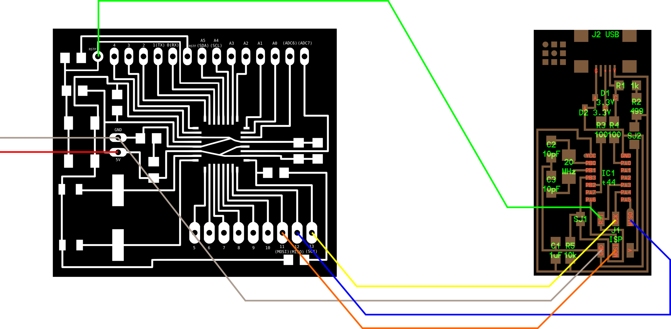
To program the board i connected it to the fab isp using the following pinout diagram
Programing the board
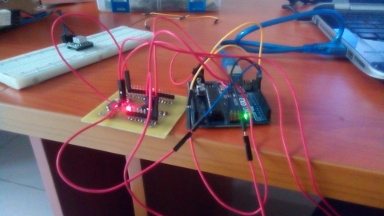
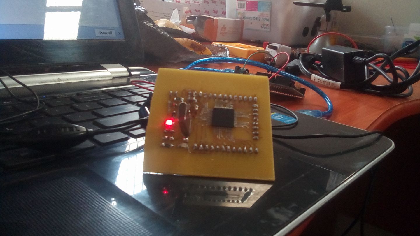
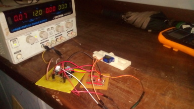
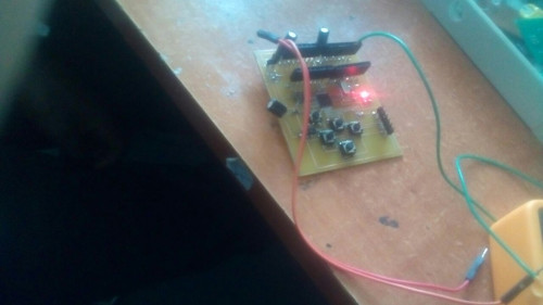
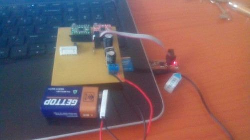
I tested the board with 12V power supply to see if it was working optimally
Testing the board
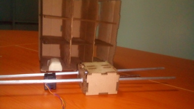
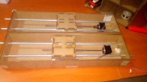
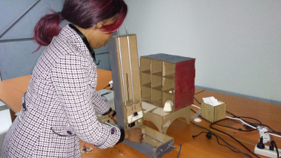
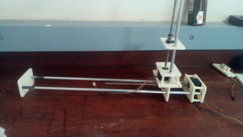
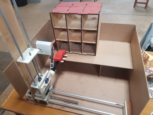
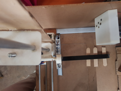
Assembly
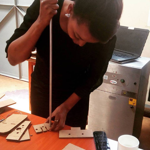
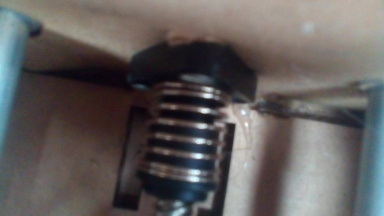
I put the parts together module by module until i had a full system. To hold them together i used hot glue and for the inner box i used screws to connect the bottom piece to the thread
fixing the rods in the holes
fixing screws
the inside of the box
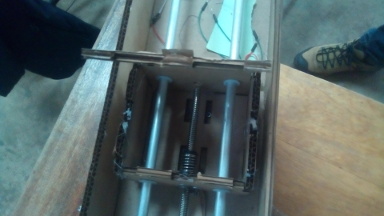
motors


fixing the rack and pinion
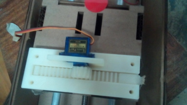
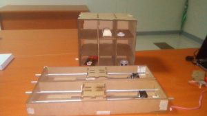
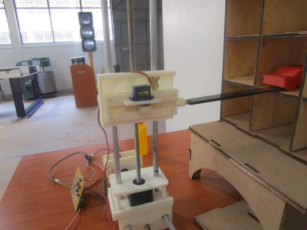
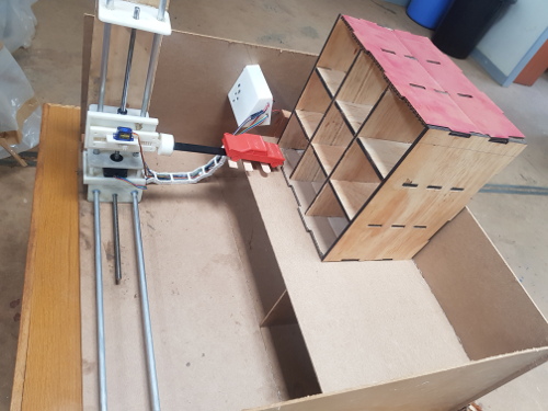
The final outcome is as seen below
lot
laser cut
Vinyl cutting
I needed to use vinyl stickers to further improve the appearance of the project. I imported the clipart and began extracting the vectors by using the trace bitmap tool.
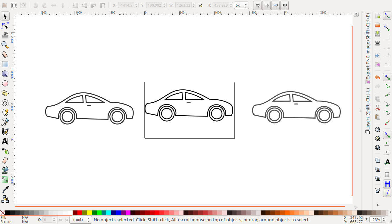
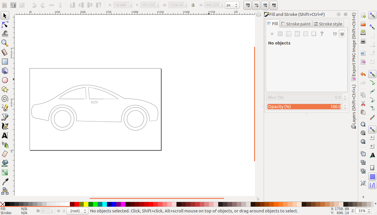
cutting
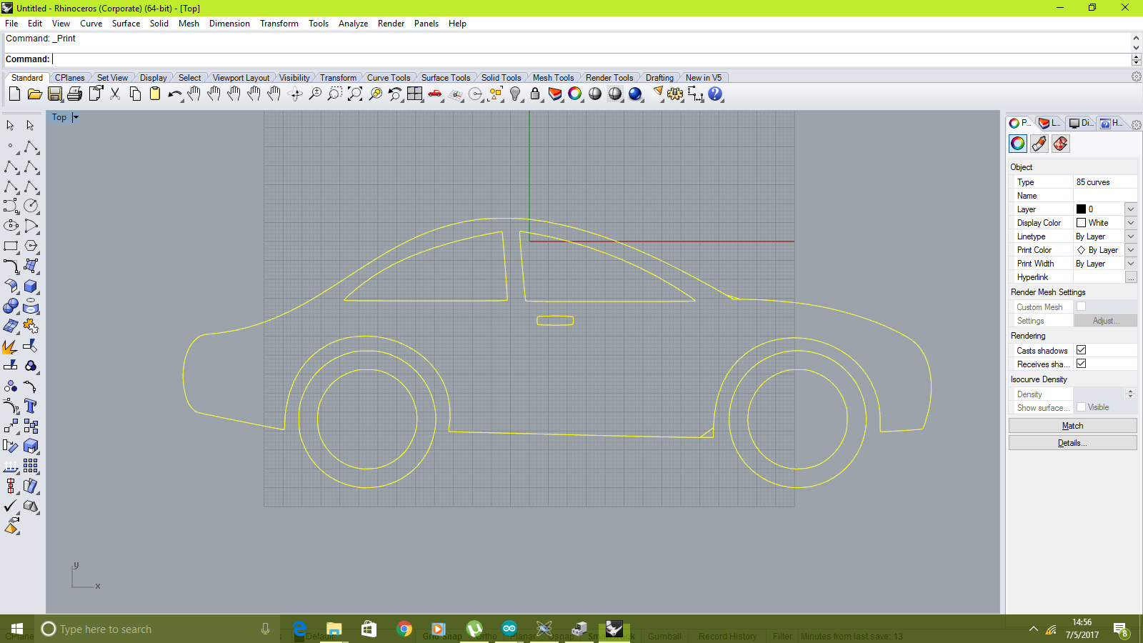
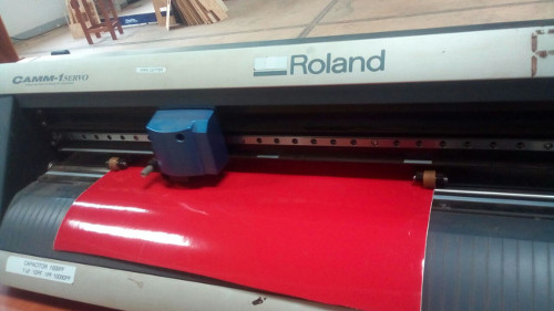
Working with the roland vinyl cutter was pretty straight forward. I loaded my file in dxf format to rhino, as shown. I then selected the print option and selected the drivers of the machine.
rhino
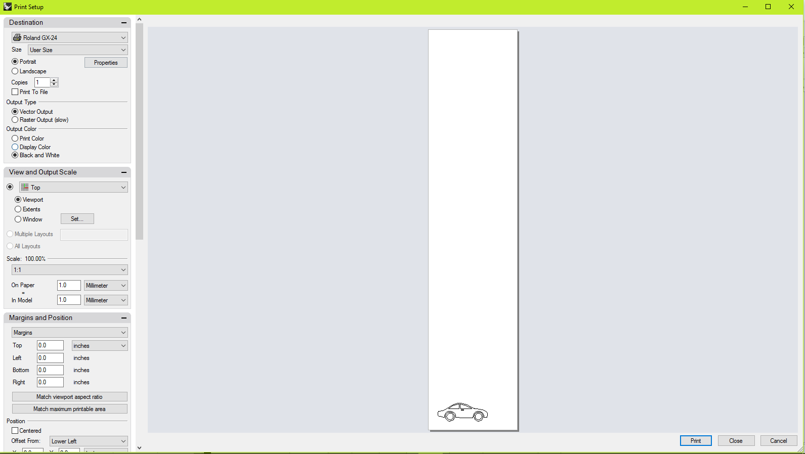
The printer options window appeared where different parameters such as force are set
printer parameters
The next step entails setting up the machine. setting the home and loading the vinyl roll and securing it.
material setup
The printing began soon after and this was the outcome after weeding
weeded
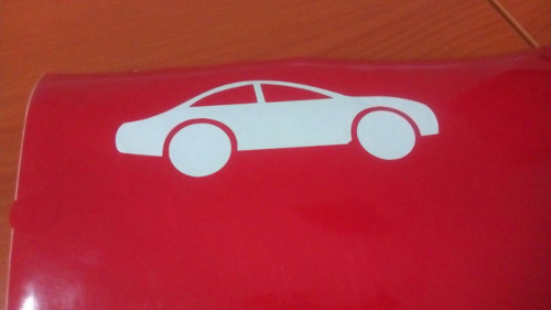
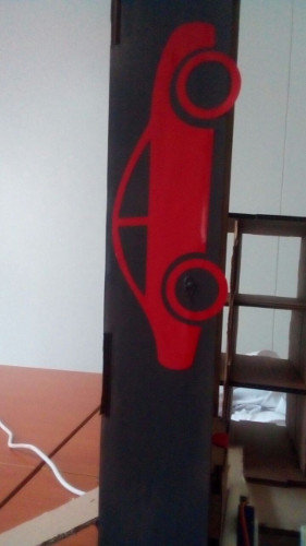
The sticker i stuck on one of the modules of my final project
sticker
The final product is as seen below
assembled
assembled
assembled
Downloads
- control board schematics
- control board
- eagle schematics
- eagle board
- The parking lot 2D model
- The stand 2D model
- The code
- Vinyl design
Links to other weeks that relate to project
BOM
| Item | Quantity | Cost |
|---|---|---|
| pololu stepper motor drivers | 2 | Kshs 600 |
| atmega 328p | 1 | Kshs 500 |
| capacitors | 9 | 200 |
| voltage regulators | 4 | 100 |
| Cardboard | 2m x 2m | 0 |
| stepper motors | 2 | 6000 |
| wires | 4m | 300 |
| crystal (16Mhz) | 1 | 20 |
| servo motor | 1 | 400 |

