Introduction
This week's assignment was to add an input device to a board i have made and program it. The input device that i chose is the ultrasonic sensor(distance).
The sensor

Definition
An Ultrasonic sensor is a device that can measure the distance to an object by using sound waves. It measures distance by sending out a sound wave at a specific frequency and listening for that sound wave to bounce back. By recording the elapsed time between the sound wave being generated and the sound wave bouncing back, it is possible to calculate the distance between the sonar sensor and the object. To measure distance it uses the formula:
distance = (speed of sound x time taken)/2 There are only four pins on the HC-SR04: VCC (Power), Trig (Trigger), Echo (Receive), and GND (Ground)
- Features:
- Operating Voltage: 5V DC
- Operating Current: 15mA
- Measure Angle: 15°
- Ranging Distance: 2cm - 4m
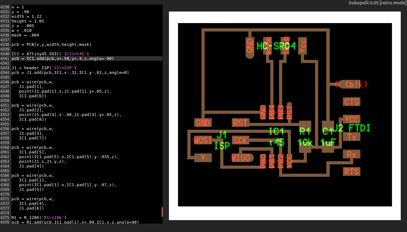
I began my journey by downloading the cad file from the archives and saving it in a text file as a .cad file. I then imported it into kokopelli as shown
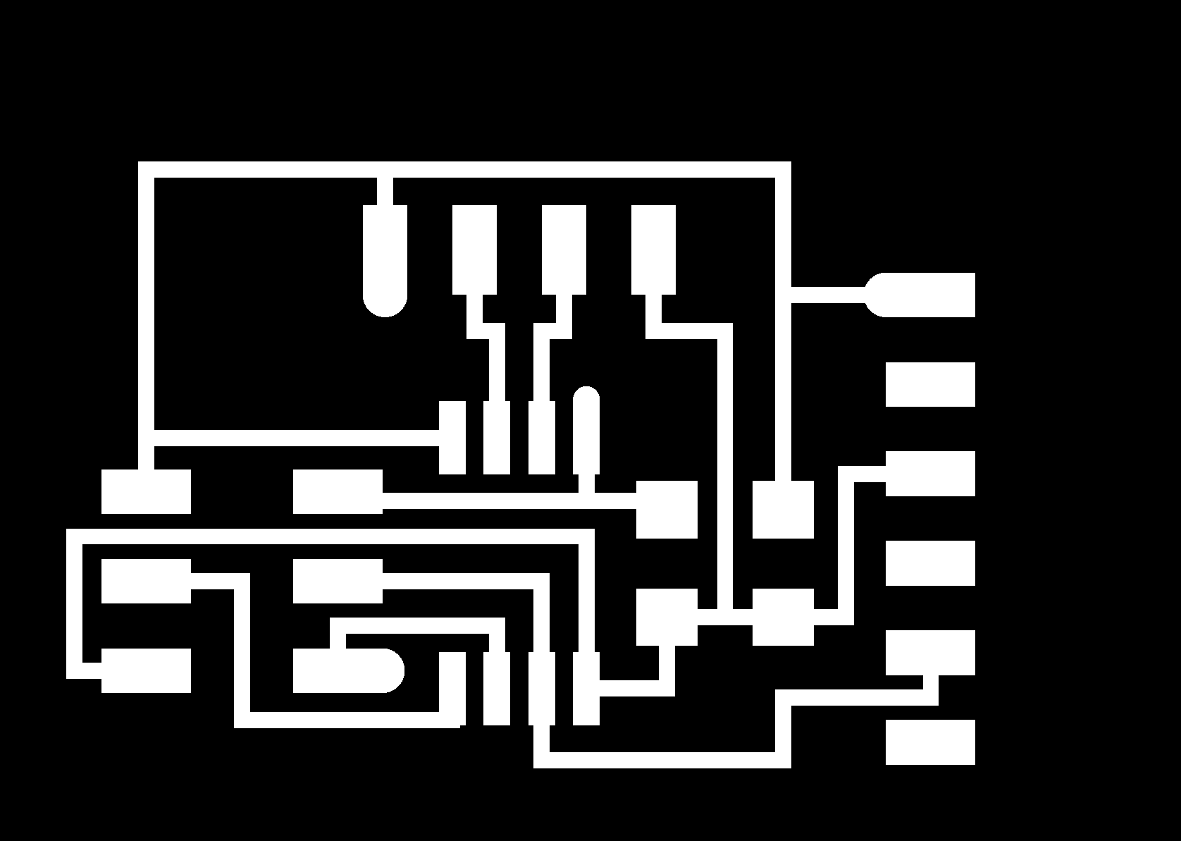
The board
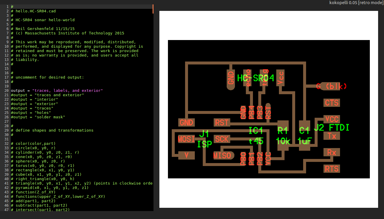
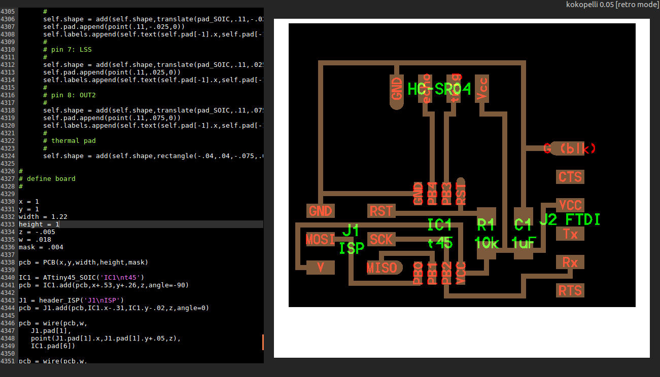
I noticed the components were too close together so i began to move them around and to increase the size of the board. i changed the size of the board by adjusting the size to the following
x = 1
y = .90
width = 1.22
height = 1.05
z = -.005
w = .018
mask = .004
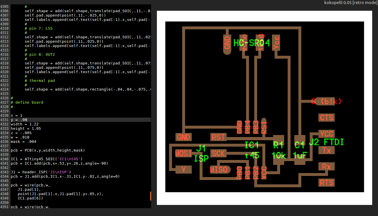
The resulting board was as shown
The board resized
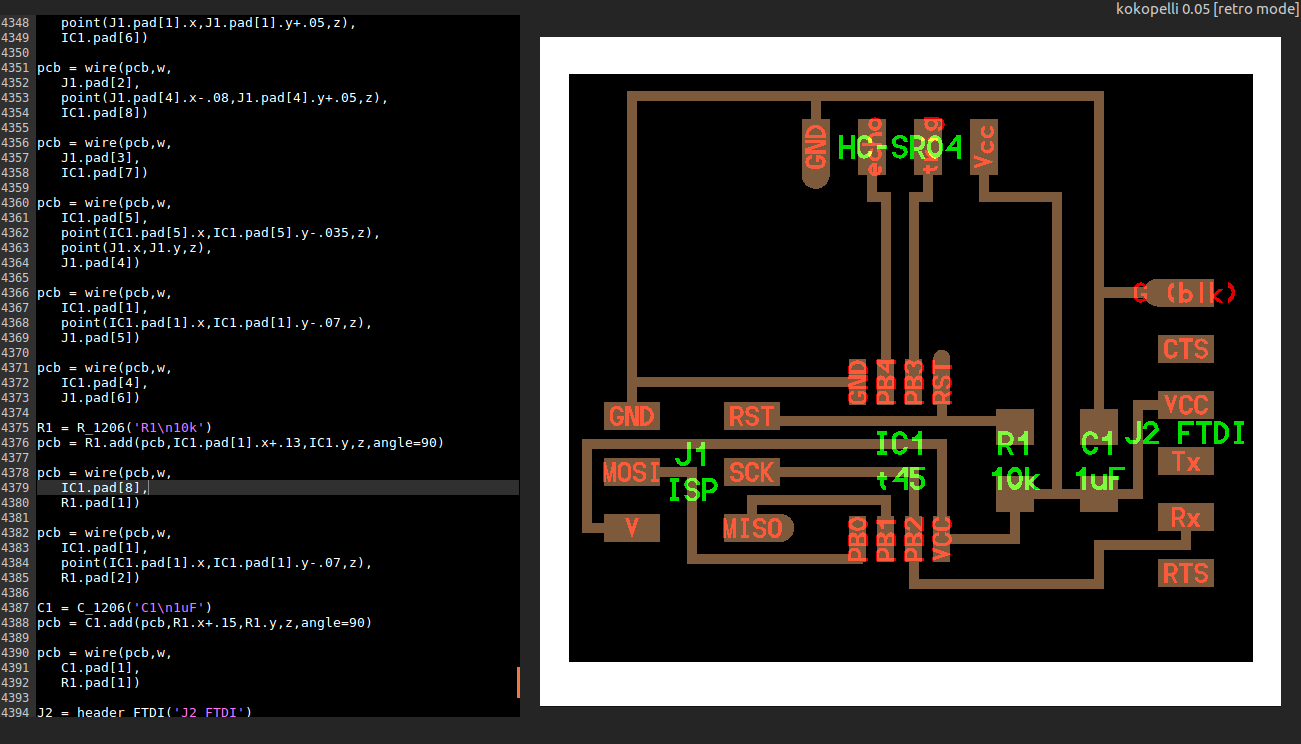
I continued to move the placing of the board so as to find the best centralised placing for it
The board moved
Once the board was centralised i went ahead to move the components around to place the pins to the edge and to give more room for the microcontroller. i moved the isp pins towards the edge and the microcontroller higher. I also moved the resistor and the capacitor to the right.
The components moved
The components moved
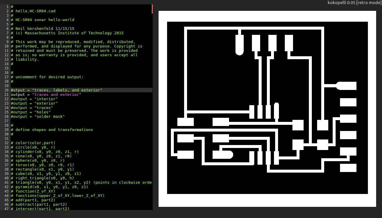
I proceeded to change the view settings to show only the traces and outline by uncommenting the view code as shown
Traces and outline
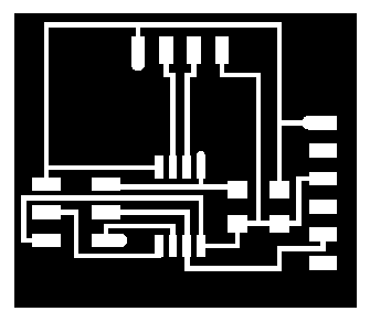
The exported png was as shown
The png
I then made and stuffed the board as shown
The board
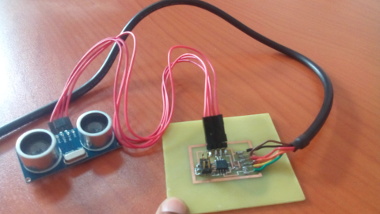
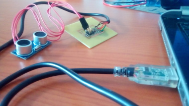
I then connected the board to the computer via FTDI cable.
connecting the board
In order to visualise the data i installed pyserial. The instructions on how to install can be found in the following Link. I then downloaded the python script from the archives. I entered the directory and keyed in the command.
python hello.HC-SR04.py /dev/tty/USB0This gave me the following GUI.
The GUI
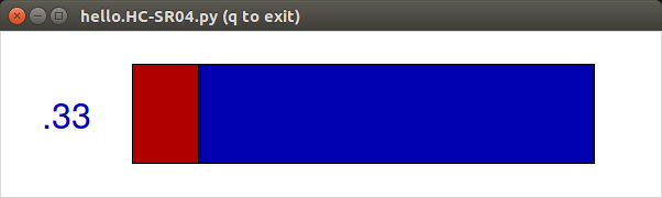
Unfortunately the GUI was not changing values on the sensor input, instead it remained a constant value of .33. After lengthy troubleshooting i was able to identify the problem as a faulty FTDI cacle. when i replaced it i was able to get a reading from the sensor as seen in the video below.
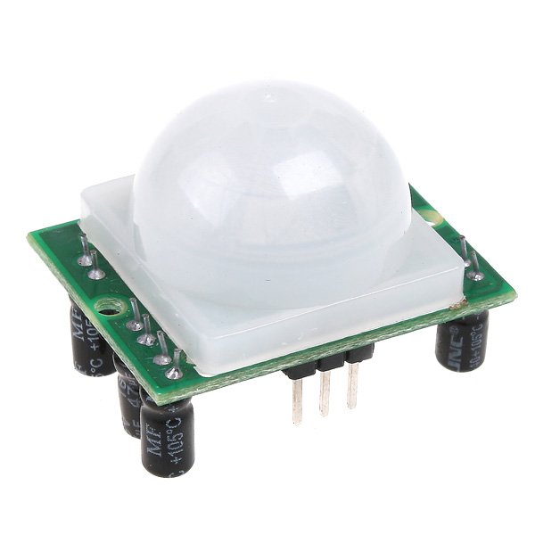
PIR sensor
The acronym PIR stands for Passive Infrared. PIR sensors allow you to sense motion and they are commonly found in appliances and gadgets used in homes or businesses. They are basically made of a pyroelectric sensor which can detect levels of infrared radiation. The sensor in a motion detector is actually split in two halves. The reason for that is that we are looking to detect motion (change) not average IR levels. The two halves are wired up so that they cancel each other out. If one half sees more or less IR radiation than the other, the output will swing high or low.
working principle
The PIR sensor itself has two slots in it, each slot is made of a special material that is sensitive to IR. The lens used here is not really doing much and so we see that the two slots can 'see' out past some distance (basically the sensitivity of the sensor). When the sensor is idle, both slots detect the same amount of IR, the ambient amount radiated from the room or walls or outdoors. When a warm body like a human or animal passes by, it first intercepts one half of the PIR sensor, which causes a positive differential change between the two halves. When the warm body leaves the sensing area, the reverse happens, whereby the sensor generates a negative differential change. These change pulses are what is detected.

For this excercise i chose to integrate a PIR sensor with a satshakit board.
Satshakit board
Pir sensor
Programing
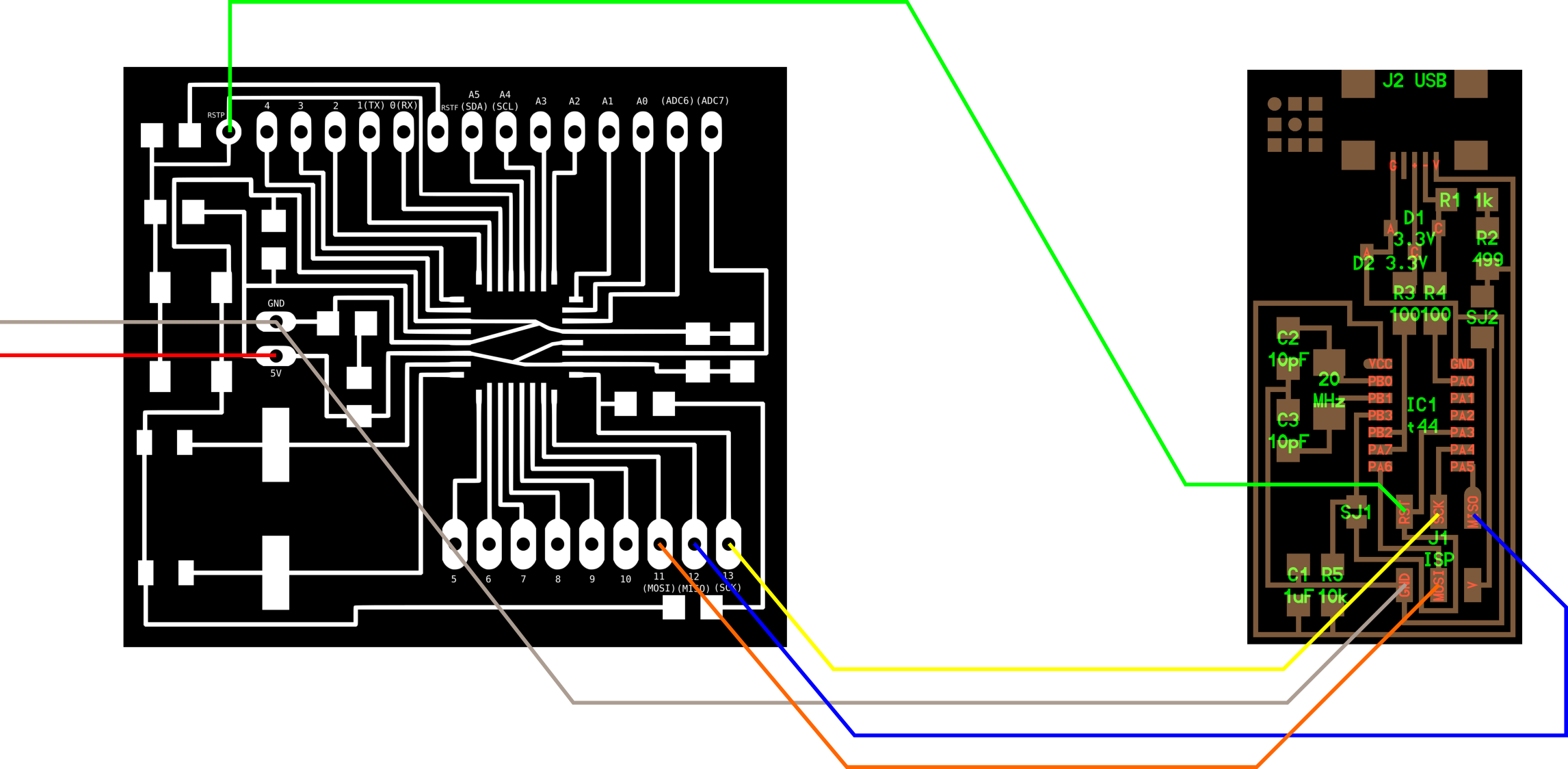
To program the board i connected it to the fab isp using the following pinout diagram
Satshakit board to fab isp connection
I then wrote a code on arduino IDE as shown and at the tools menu i chose the arduino uno board and programmer as usbtiny. On the file menu i chose upload using programmer and the code was successfully uploaded
arduino program
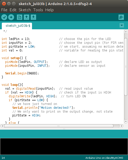
The program sets the led connected to pin 13 on whenever an object is nearby. The program also sends out a message to the serial ouput that says "motion detected". My PIR sensor was connected to pin 9.
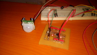
Satshakit and Pir sensor
Problems and solutions
The first excercise dd not work as intended at first. Finally when i changed the FTDI cable i was able to get the desired results