Week #13 Input Devices
Assignments
Software Used
- EAGLE 7.7.0
- GIMP2.0
- Roland VPanel for MDX-40A
- Fab Modules
- Arduino IDE
Machine Used
- CNC Router Roland MDX-40A
Exercise Repo
You can find all files used in this class in the Fab Academy repository in the button below or a backup in this Google Drive folder.
Past experience
I've only worked with a light sensor (LDM) before. But I just build the circuit. The challenge for this assignment will be deal with the design and programming the PCB.
Log
2017 06 13 Designing and building a two buttons board
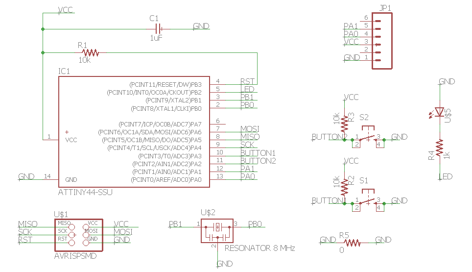
For this assignment, my plan is to do a board with two buttons and one LED to do a network with my dimmer module, the board that I built on Exercise 10. My intention is to control the dimmer (slave) through the buttons (master) and use the LED as a feedback that the button was pushed. By now, I will focus on design and build the two buttons board, the master one.
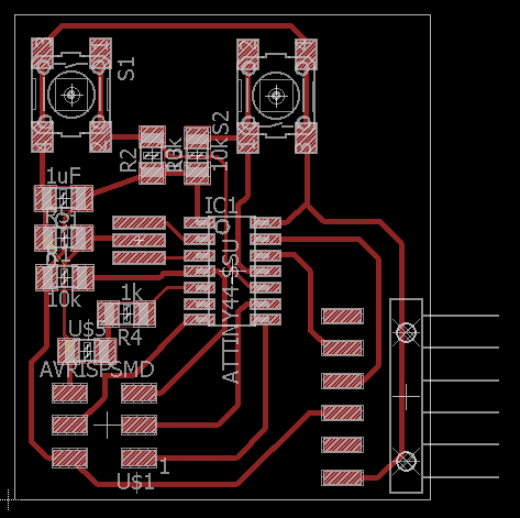
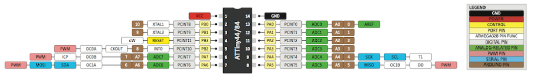
I did this assignment at the same time of Exercise 15 after studied a little bit more about I2C. I used as reference the hello board built on Exercise 6. As I used the ATTiny 44 microcontroller, the pins I had to use for I2C communication were pin 7 (SDA) and pin 9 (SCL). They were the same as MOSI and SCK, respectively. As I use the MISO and SKC pins just for programming, I was able to use them as SDA ans SCL when code was running. I had a little difficult in finding witch pins were the Tx and Rx at the ATtiny44A, since it was not written on the its pins schematic. Then Kenzo said me that in the ATtiny44A there are predefined pins for Tx and Rx. I followed the same pins used on Exercise 8. The pictures bellow show the process of designing and fabricating this PCB. For the fabrication, I used the same settings on Fab Modules I was using in the past exercises (see Exercise 4 to see it in detail).
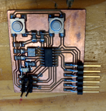
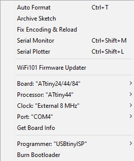
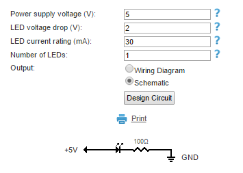
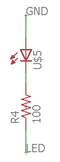
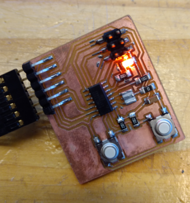
With the master board ready, I burned bootloader using the settings presented in the picture bellow, and tested it with Arduino Blink Example, but my board didn't work. First thing I did was to change the LED, since it was not responding to a diode test with a multimeter. But it was still not working. The second thing I did was to verify the pins I was using in the Arduino code. And I noticed that I was using the wrong one. I was using the pin 5, because it was the one written on the schematic, but in fact, I would use number 8 in Arduino, according to the scheme showed bellow. I fixed it in the code, uploaded it to my board, but was still not working. But now, my LED was receiving the right voltage, alternating between 0 and 5V, measured by a multimeter. My next step was to verify the resistor on LED calculator.I assumed that it would be 1k ohm, but when I calculate, it actually should be 100 ohm. I change the resistor, and was still not working. I knew that the issue must be with the LED, and with Kenzo's help, we noticed that the LED was in the opposite orientation. I fixed it, and then, my board worked! The pictures bellow show this process.
Next step was to test if my buttons were working. To do it I did a simple modification on the Arduino Button Example to allow me test the two buttons in the same code. I uploaded the code to my board and worked in well!
2017 10 13 Ultrasonic sensor HC-SR04
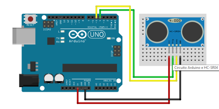
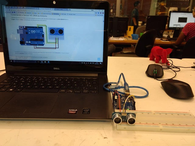
The goal for this task was to connect the HC-SR04 sensor to my Fab Kit 0.5, in order to prototype the suggestion that Neil gave me for my final project. The first step was to learn how to use the sensor connecting it to a Arduino Uno and a breadboard. For this, I followed the tutorial from FlipeFlop. I had to download the Ultrasonic library and save it to Arduino IDE libraries. The pictures bellow show this test and the code used in it. This code can be found in the zip folder, inside the folder "HC-SR04".
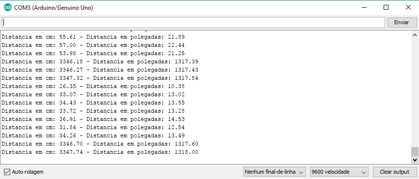
//Autor: FILIPEFLOP //Modified by Victor Macul //Loads the ultrasonic sensor library #include//Defines the pins for the trigger and echo #define pino_trigger 4 #define pino_echo 5 //Initializes the sensor on the pins defined above Ultrasonic ultrasonic(pino_trigger, pino_echo); void setup() { Serial.begin(9600); Serial.println("Reading data from sensor..."); } void loop() { //Read the sensor information, in cm and in float cmMsec, inMsec; long microsec = ultrasonic.timing(); cmMsec = ultrasonic.convert(microsec, Ultrasonic::CM); inMsec = ultrasonic.convert(microsec, Ultrasonic::IN); //Displays information on the serial monitor Serial.print("Distance: "); Serial.print(cmMsec); Serial.print(" cm or "); Serial.print(inMsec); Serial.println(" in."); delay(1000); }
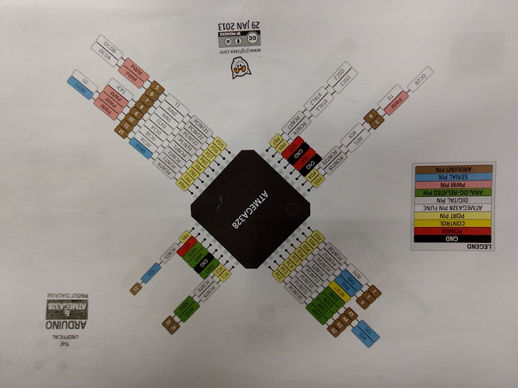
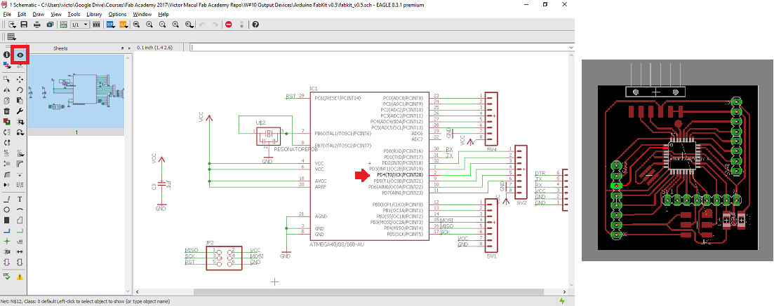
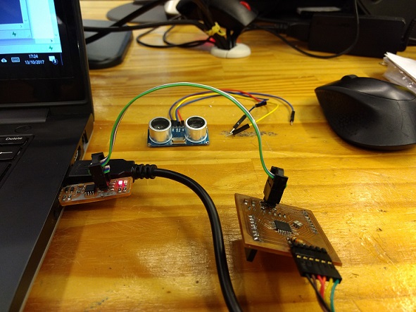
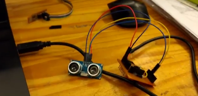
The next step was to connect the sensor to my Fab Kit 0.5. To do it I uploaded the code through Arduino IDE to my microcontroller and connected the sensor using some jumpers. To identify were the pins 4 and 5, I used the microcontroller schematic showed in the picture bellow, and also the . The following pictures illustrate the whole process.