- Week 4 +
electronics production
Tasks
- Milling
- Stuffing
- De-bugging and Programming
Step-1 Milling
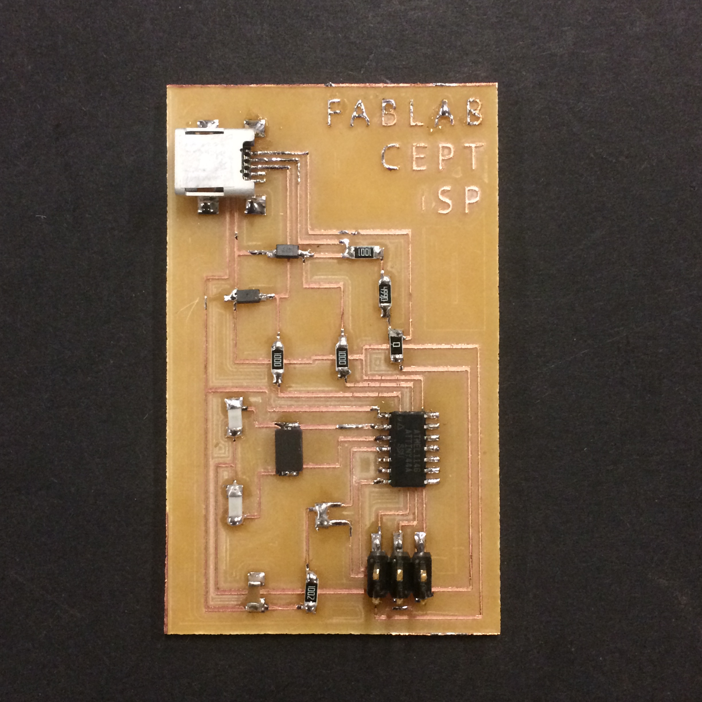
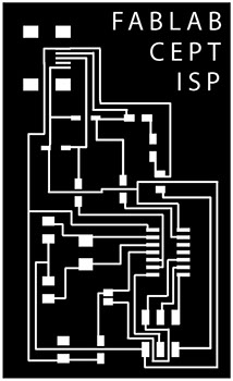
For this week's exercise, I am using FabISP re-designed by 2016 Fabacademy gradute Rudrapalsinh Solanki. Below is the image of the .png file that has the connection of the various components of the ISP board. For milling I am using 1/64" diameter drill bit.
Below image file is used for cutting the outer boundary of the board. For milling this file, I am using 1/32" diameter drill bit.

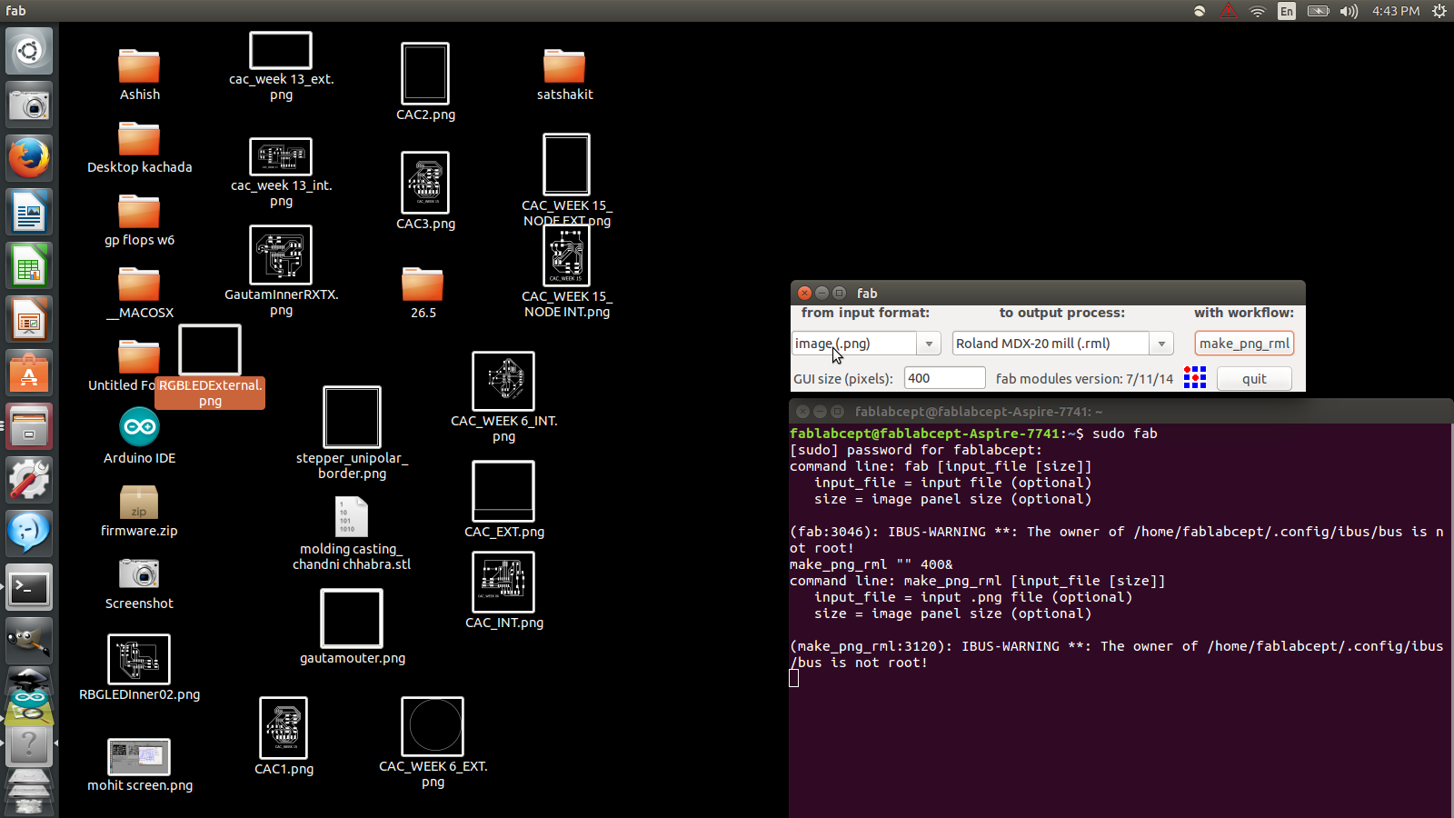
Since I have limited knowledge of using Ubuntu operating system, I am documenting the each and every step, right from opening the file to creating .rml file for milling FabISP. I am referring 2016 Fabacademy graduates Rudrapalsinh's and Tapan's documention for this week's work. Now the first step is setting up Fab Module in Terminal.
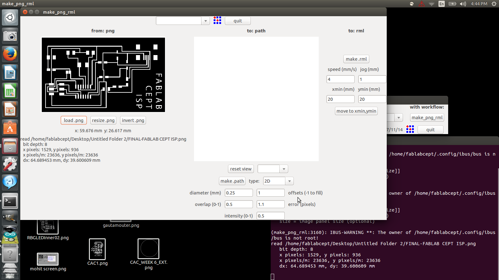
Once fab module is open, for input format select image (.png). FabIsp has .png file format, so we have to select this option. Now the machine requires .rml format for milling, so for output process select Roland MDX- 20 mill (.rml).
Next step is to load the .png file by click on load.png.
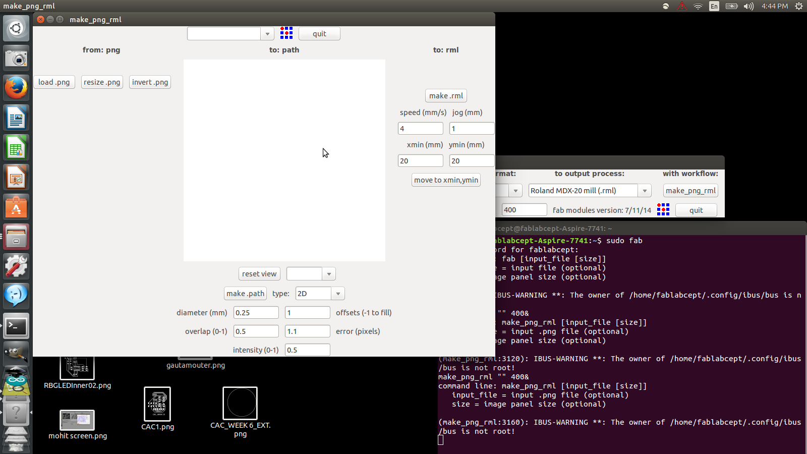
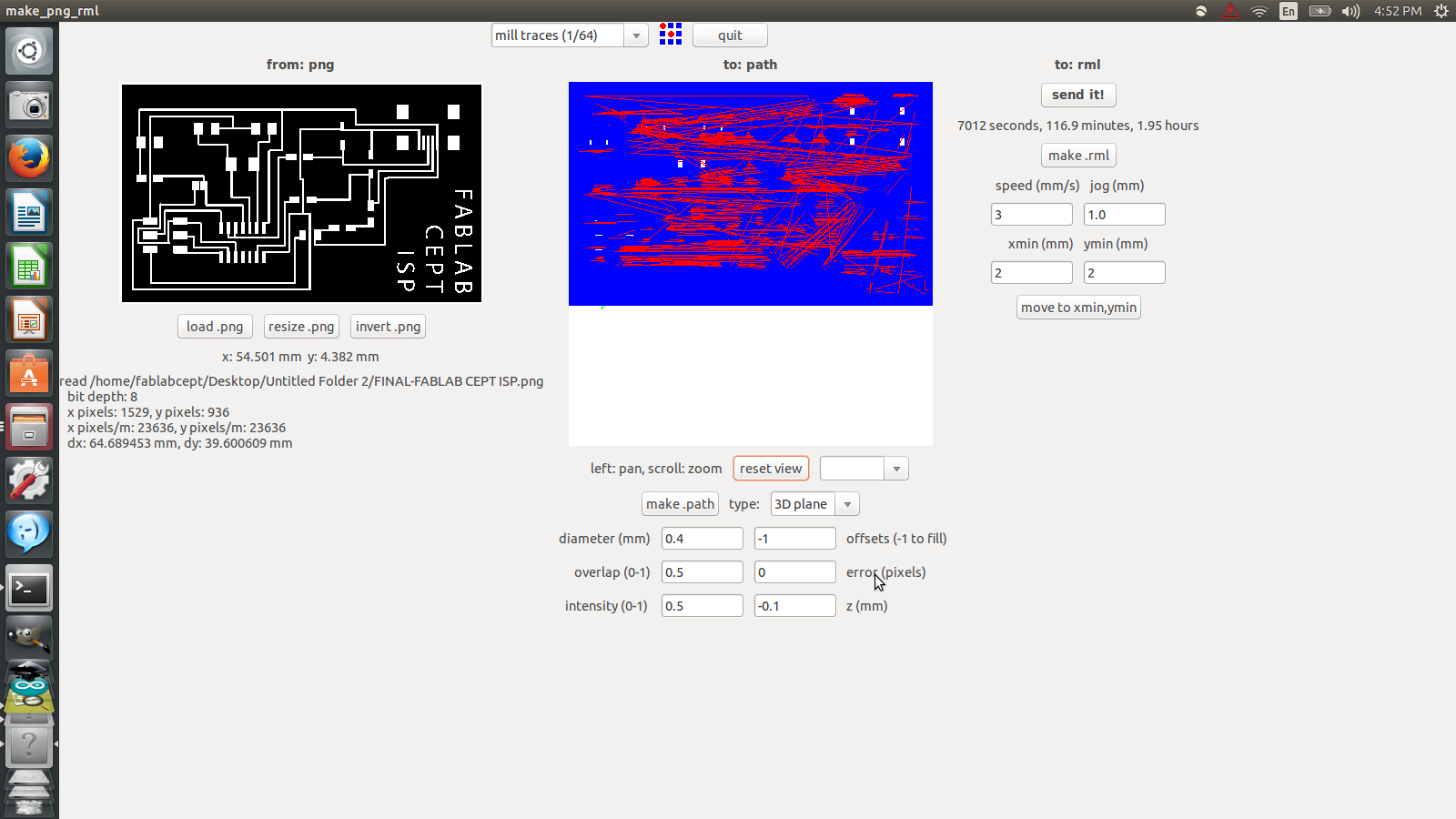
After loading the file, milling parameters are to be set. To mill the traces for the pcb, select mill traces (1/64) in the top-center selection box.
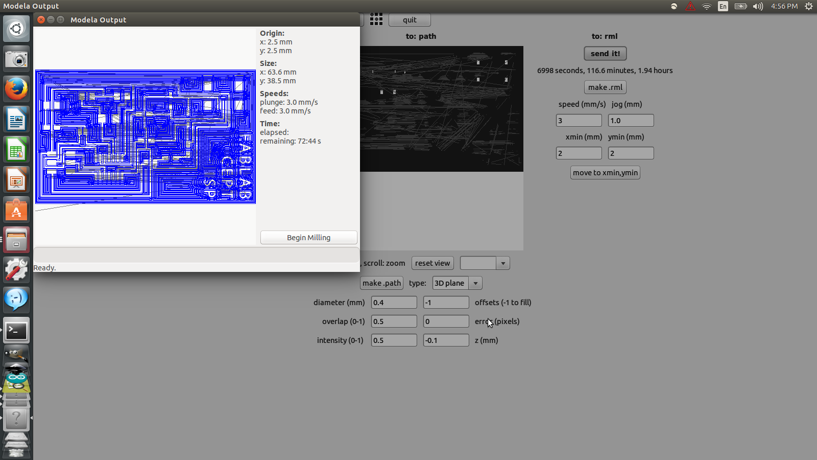
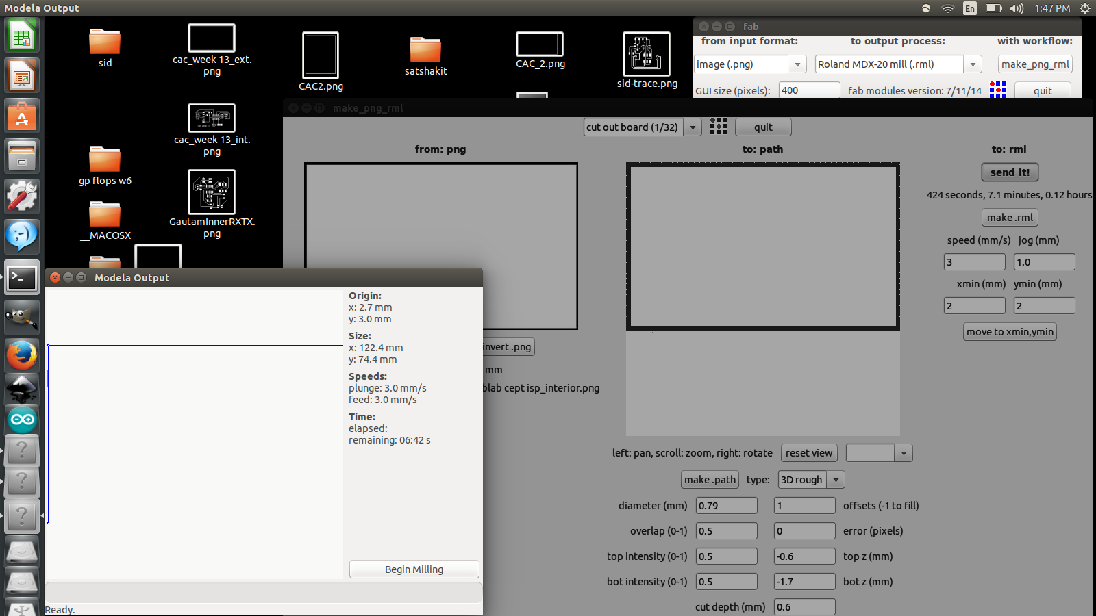
Then set other parameters, change the diameter to 0.4 mm. and offsets to -1. Then set the z-movement value to -0.1 mm to avoid milling just over the surface of the pcb. Now hit make path to create path for milling. Now fix the board on the machining bed and set required x and y position on the board using tabs on the right-hand side of the machine. Next step is to hit the make.rml for creating milling toolpath. Now upon pressing the send it! tab, another box is opened where milling is launched by clicking begin milling tab. Note: Ensured that the Roland Modella is connected and not in View Mode.
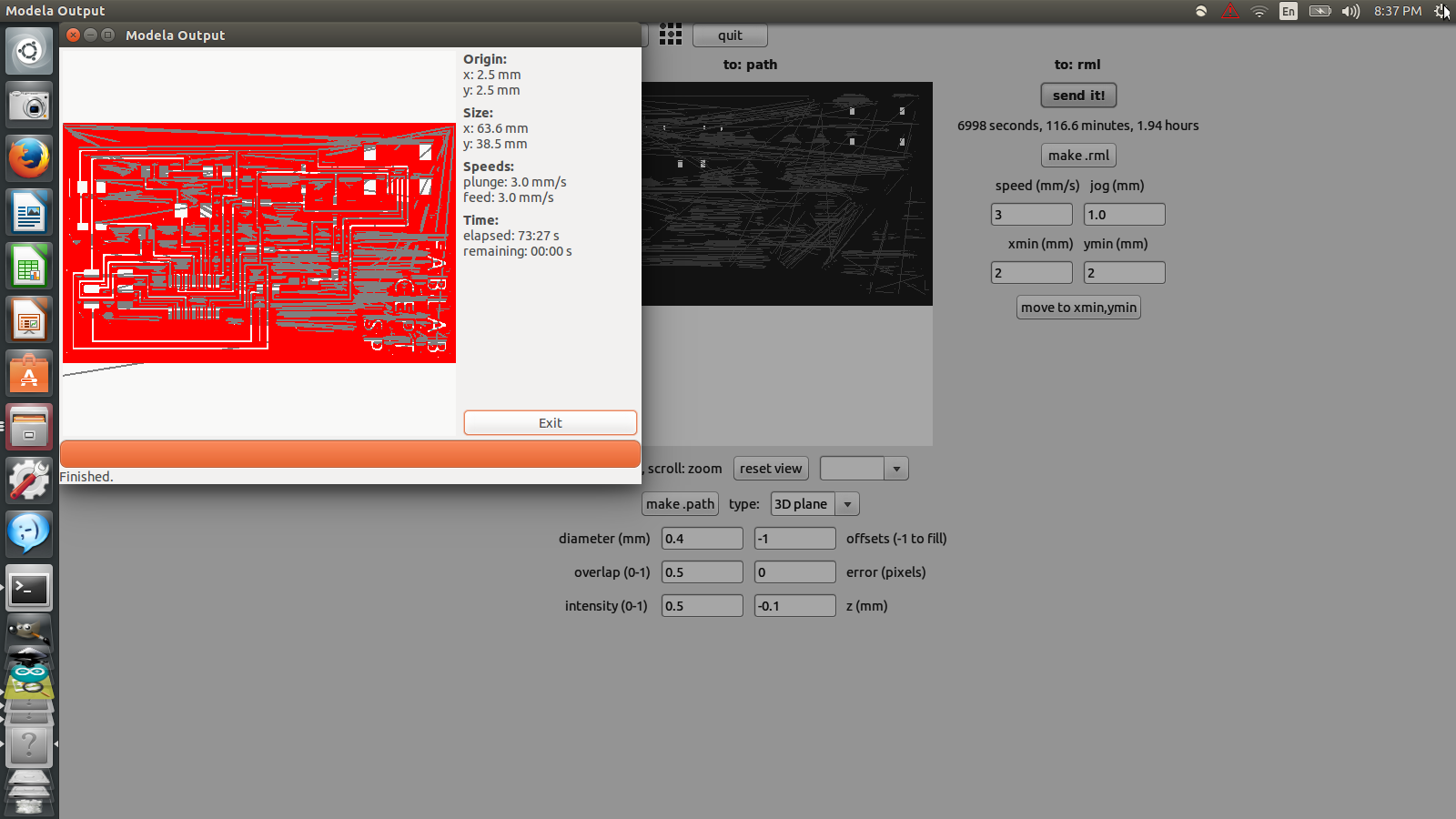
Once the milling is finished, the screen looks like this. Turning the toolpath from blue to red.
Following the above steps for milling traces, similar process is employed with Interior .png file. Here, 1/32 inch bit is replaced for through cutting of the board.
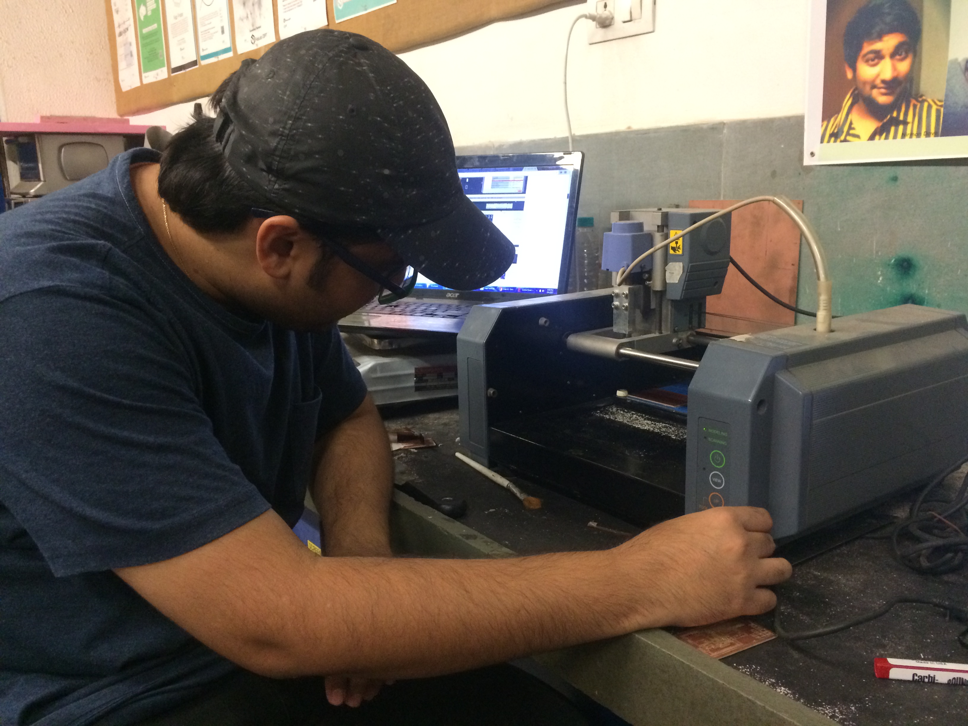
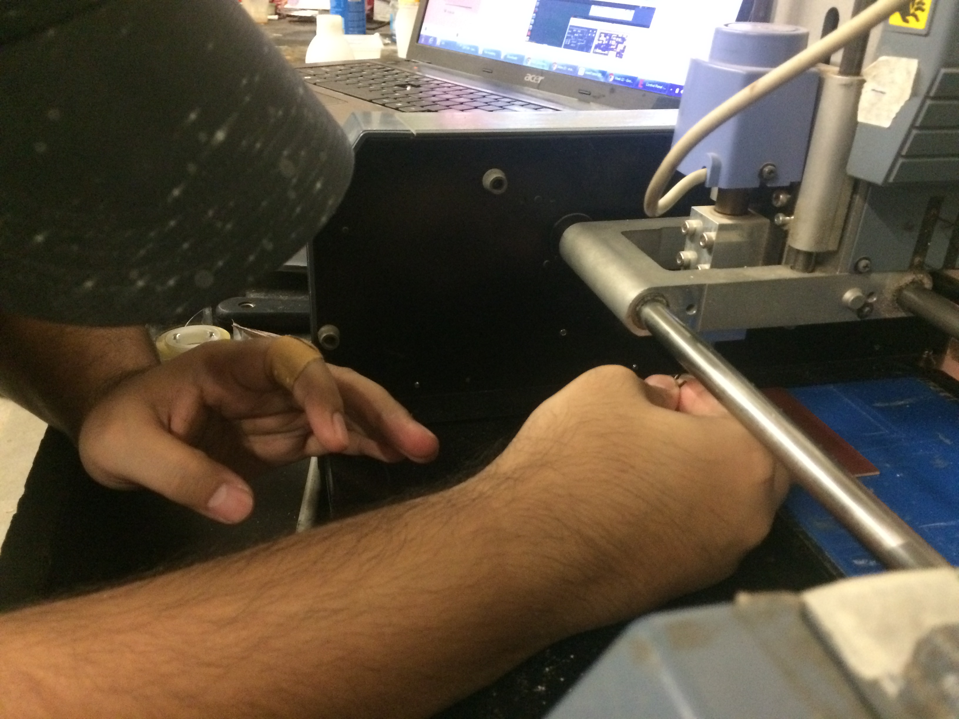
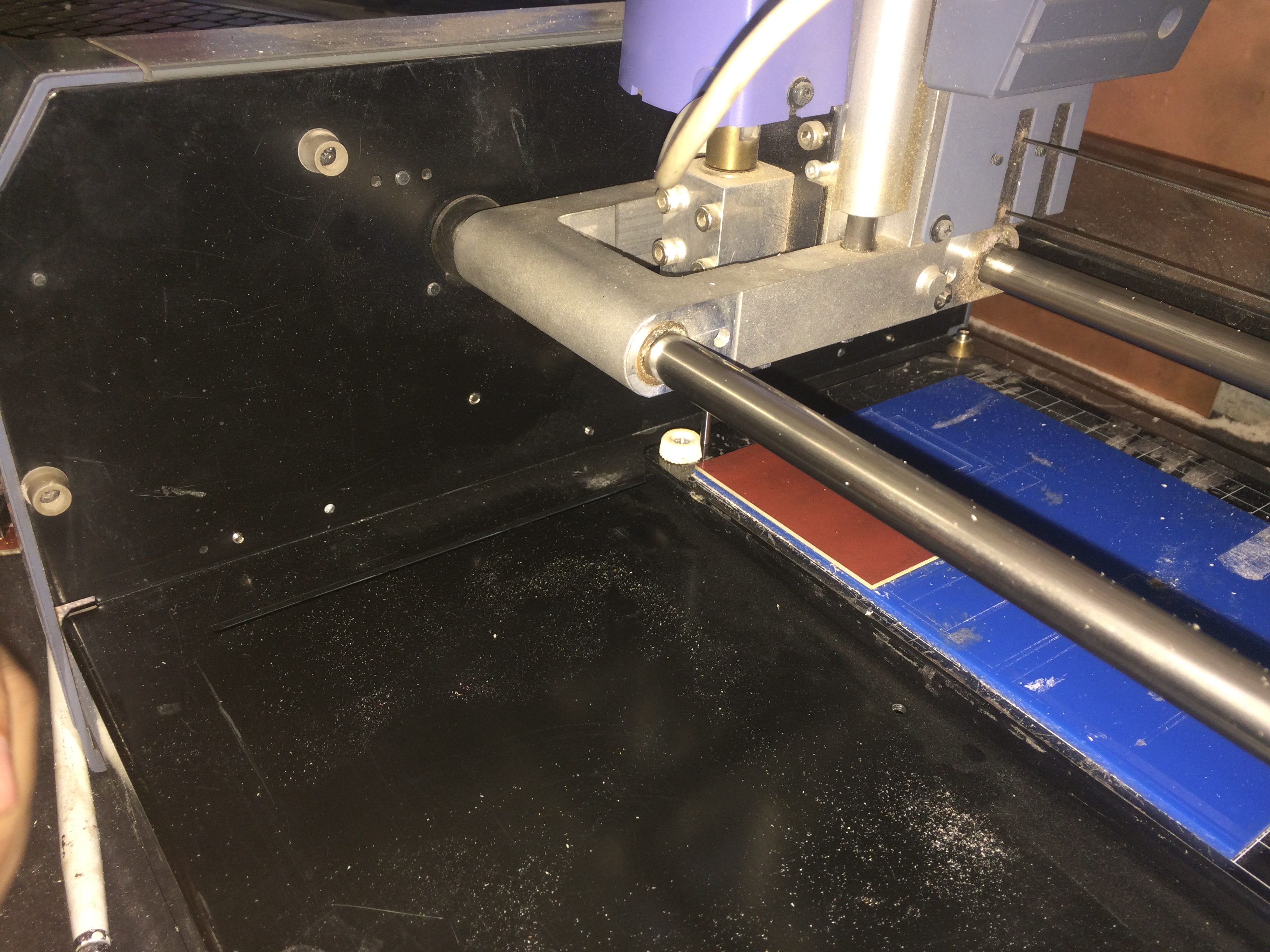
Following three images show fixing of the drilling bit and pcb on the machine:
This is a complied video of FabISP milling:
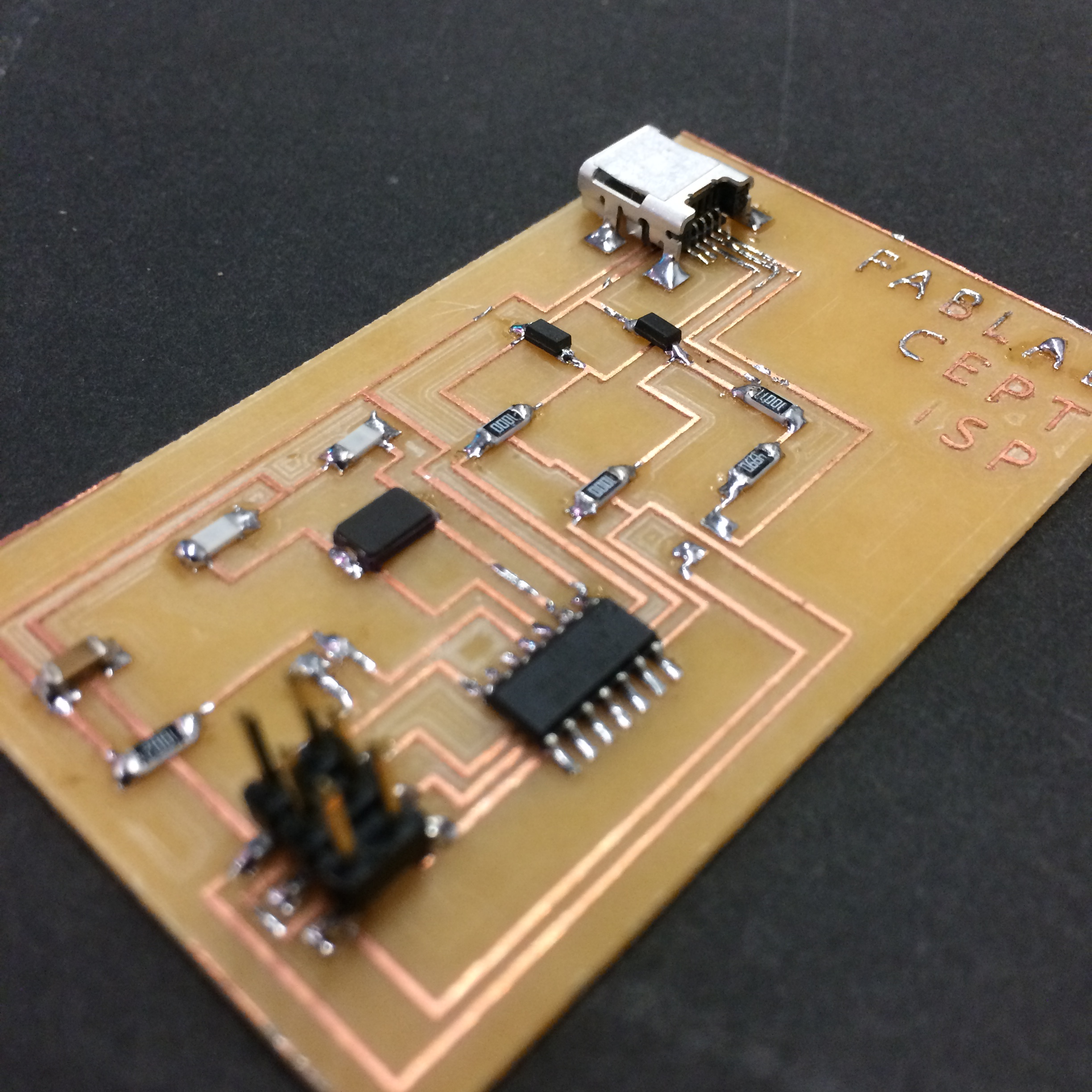
Once milling is done the board looks like this. It requires some cleaning of the surface before stuffing. Note: Cleaning of the surface needs to be done carefully, ensuring no damage is being made to the circuit.
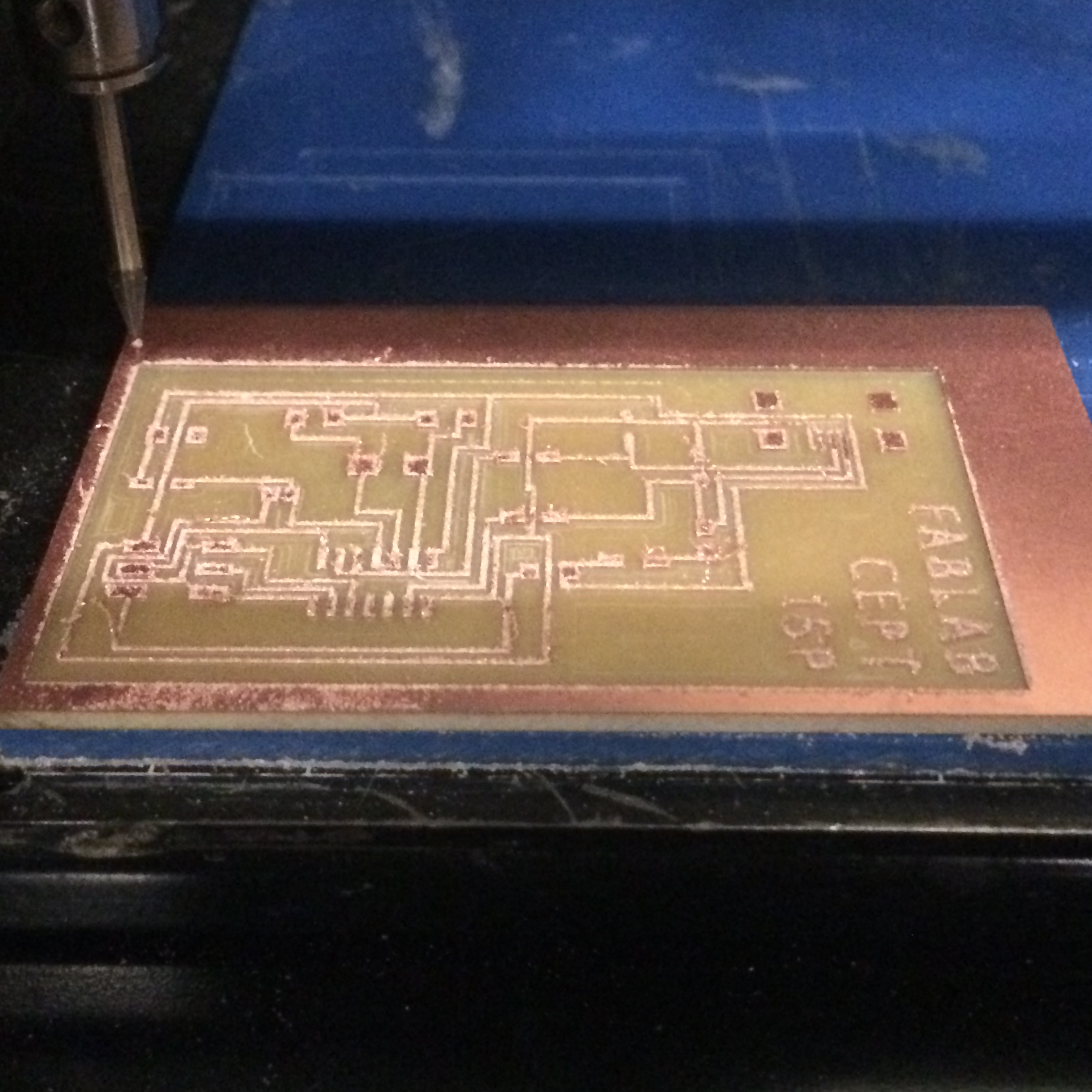
After cleaning the circuit board it looks like this. Quite happy to see that it is intact and neat, though it took hours to mill.

Step-2 Stuffing
For soldering the components, I picked up following components that are required for making the FabISP board. All components are available in our lab's inventory.
Now I started carefully stuffing the components on the board. It took me more than an hour to solder the board.
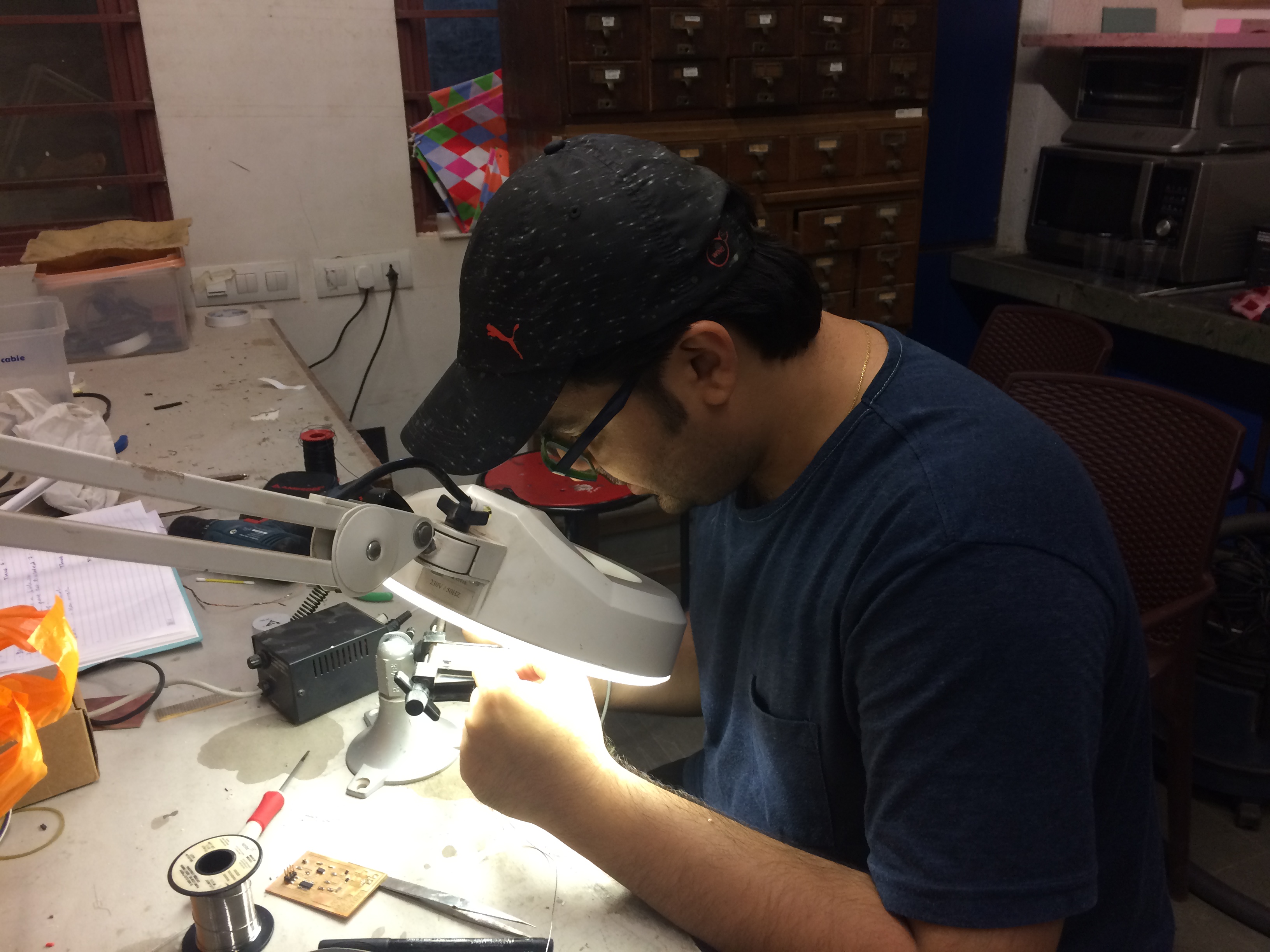
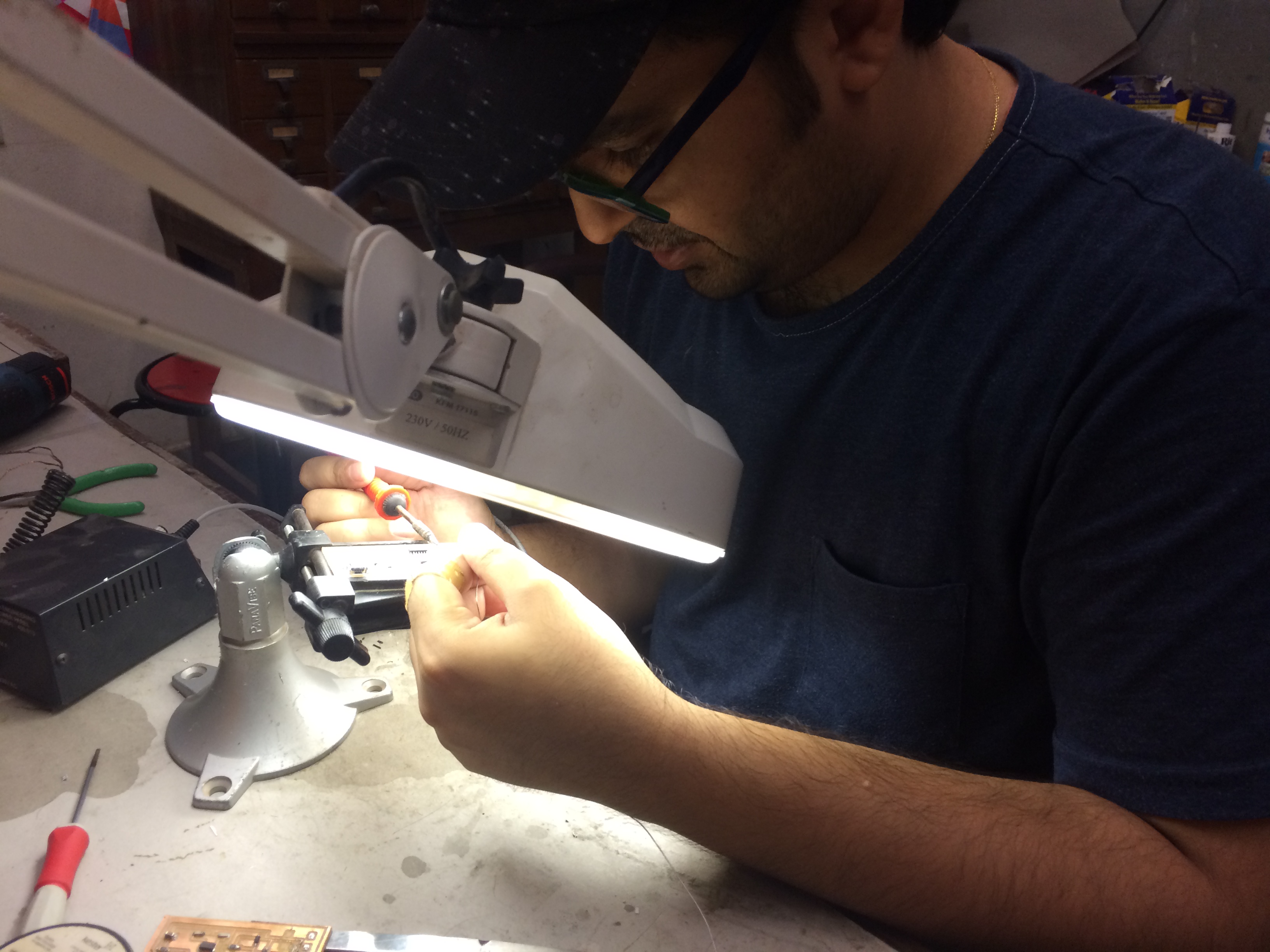
This is how it looked like after stuffing the board. Now it's time to test the functioning of the board.
I made a video of the board showcasing working of the board with AVR MKII. I could see the orange light flashing and also the green light on reversing the pin. Thank you Siddharth Arya for making the video.
Step-3 De-bugging and Programming
Now the next step is to program the FabISP. I referred FabISP: Programming tutorial for step by step procedure. As mentioned in the tutorial, the first step is to intall the necessary software for Ubuntu operating system and download the firmware.
Software Installation
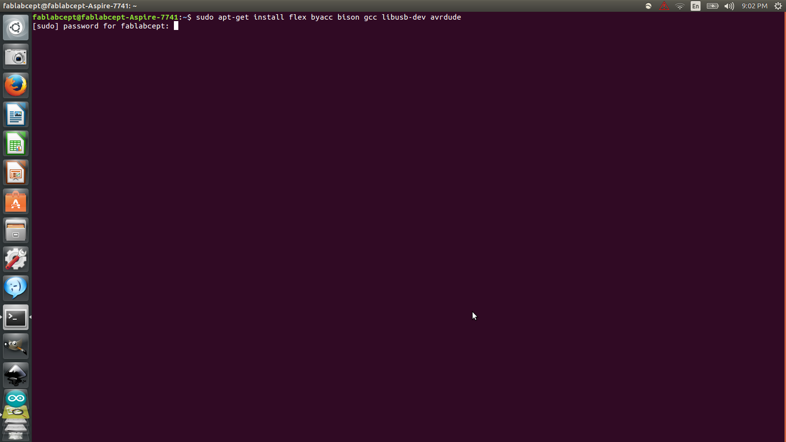
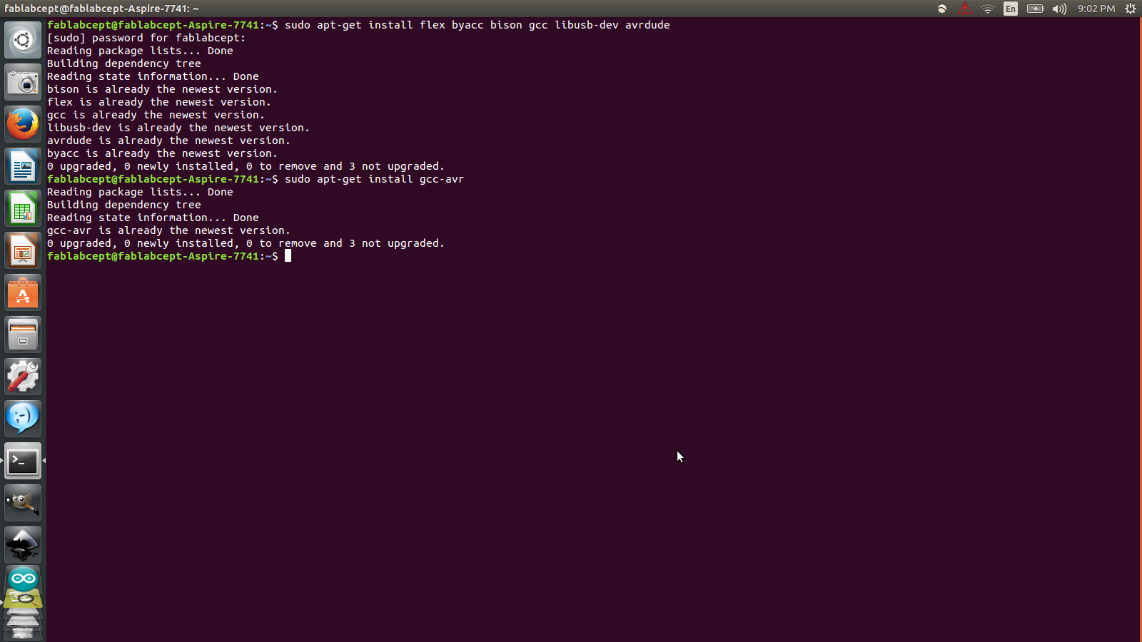
Open Terminal and type:
sudo apt-get install flex byacc bison gcc libusb-dev avrdude
Then type:
sudo apt-get install gcc-avr
Then type:
sudo apt-get install avr-libc
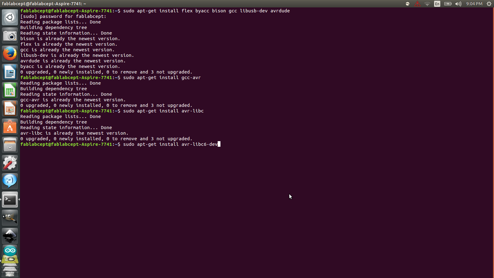
Then type:
sudo apt-get install libc6-dev
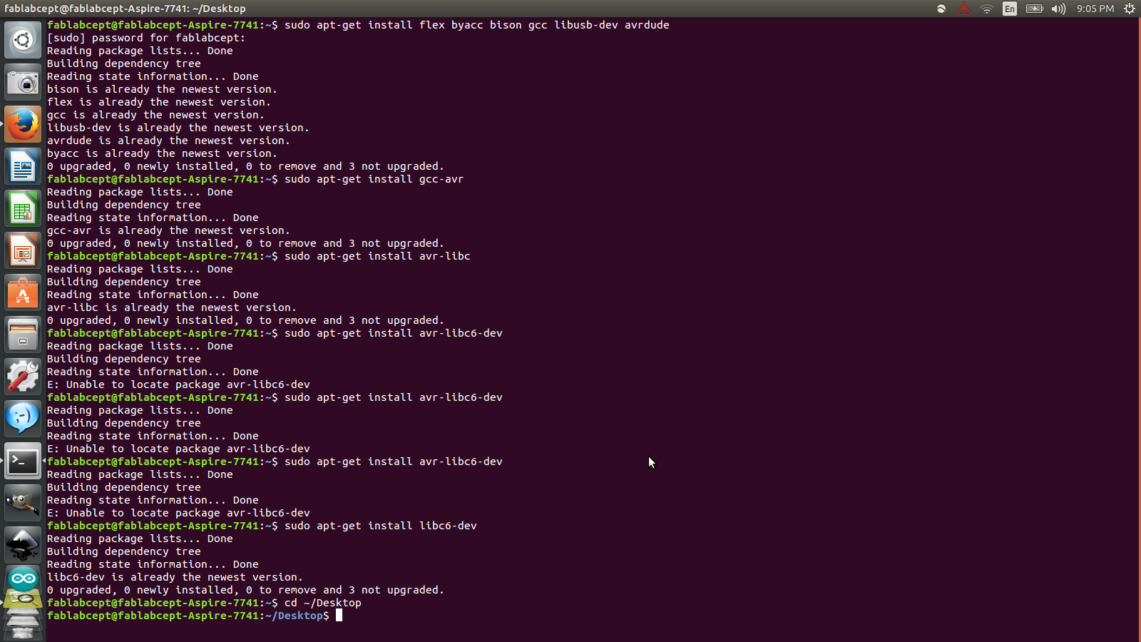
Then move to the desktop
cd ~/Desktop
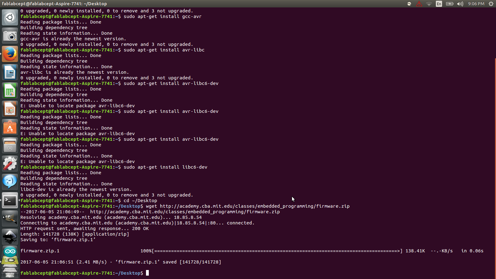
Then download the firmware
wget http://academy.cba.mit.edu/classes/embedded_programming/firmware.zip
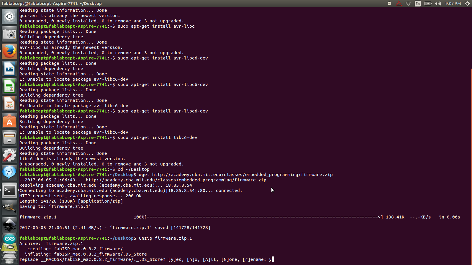
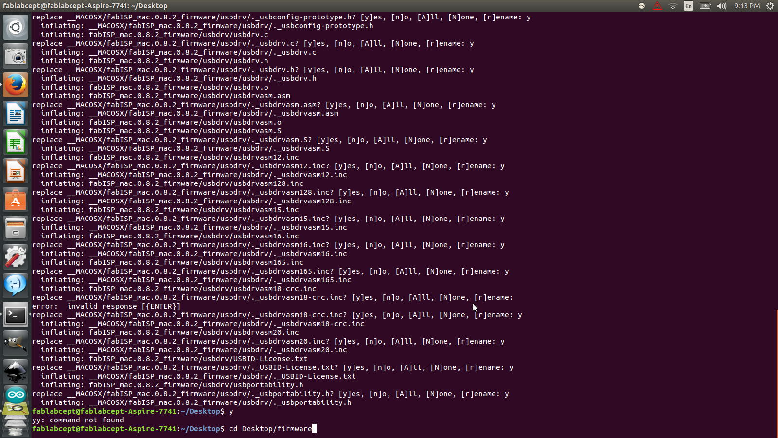
Then unzip the firmware
unzip firmware.zip
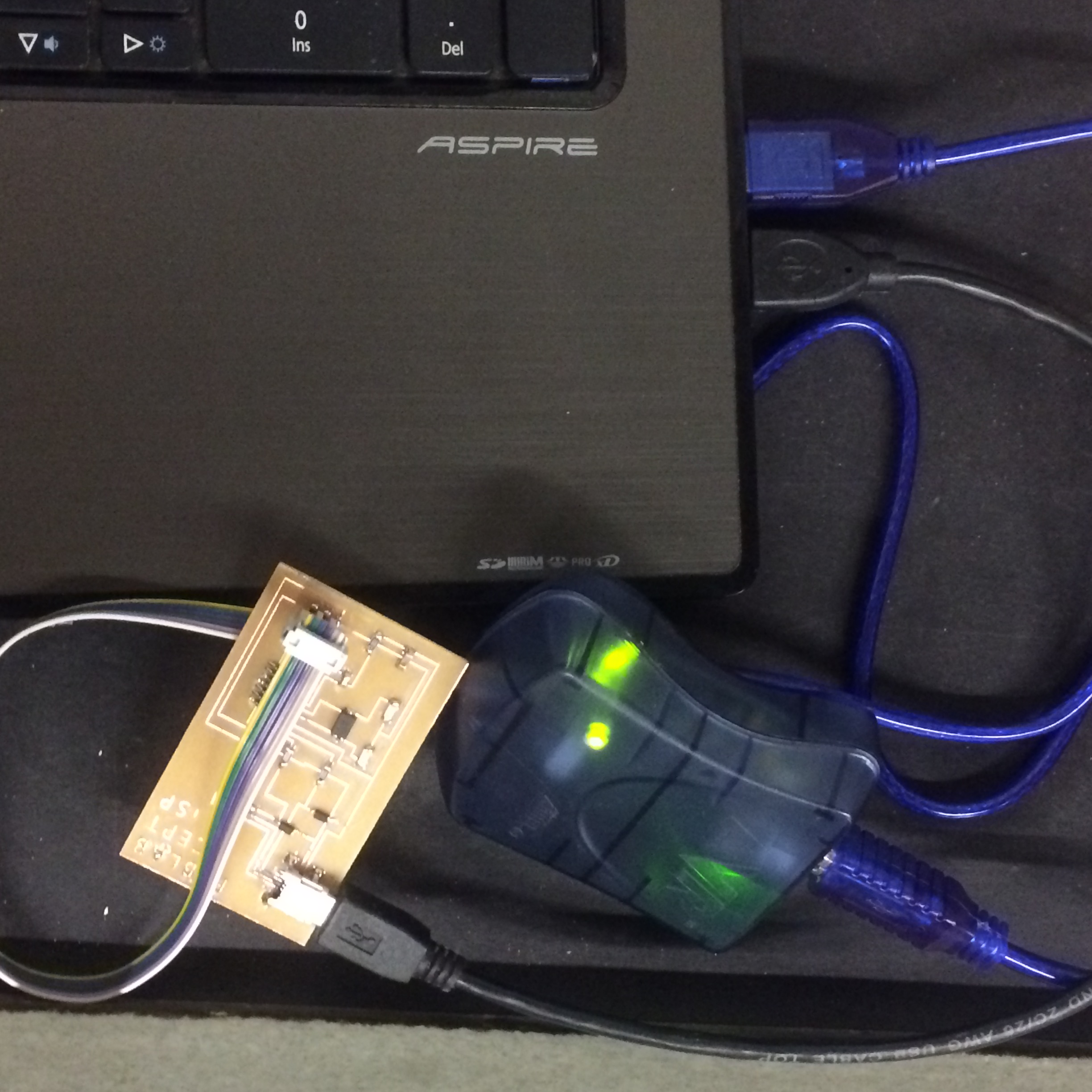
Power and Program the FabISP board
Now the next step is to power the board. To do so, I plugged in the FabISP into the computer. And then AVRISP, a separate programmer, is plugged in to the 6-pin programming header. Green Light signals that the header is soldered correctly and the board is getting power.
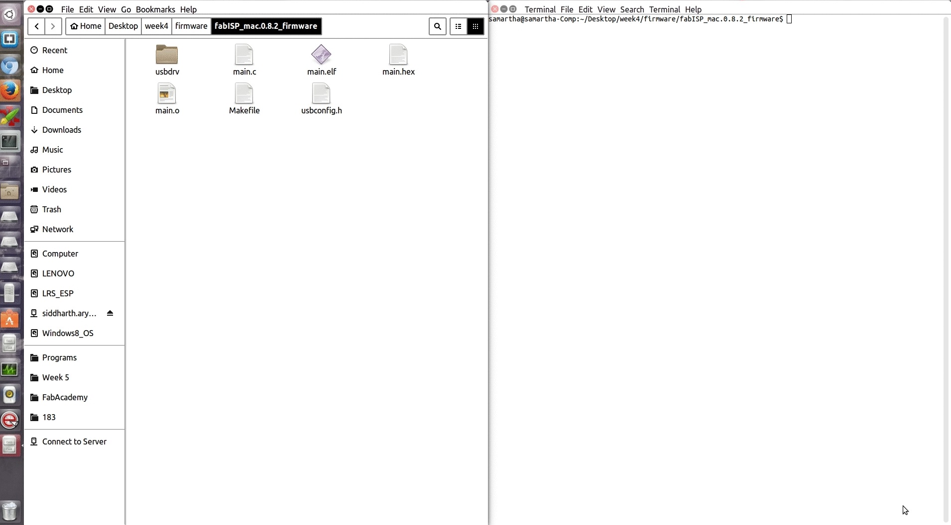
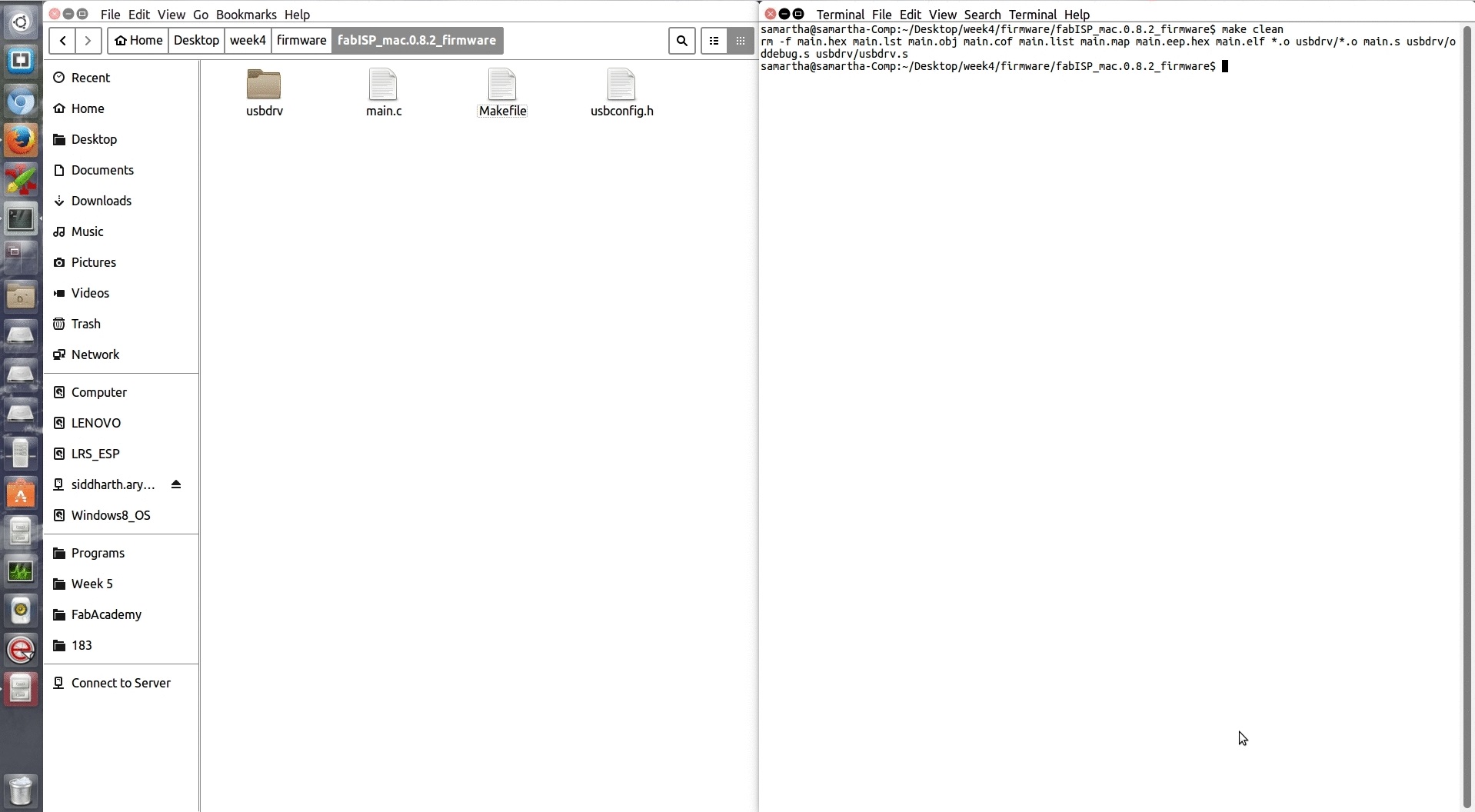
Next, compile the firmware, Type: make clean
success!
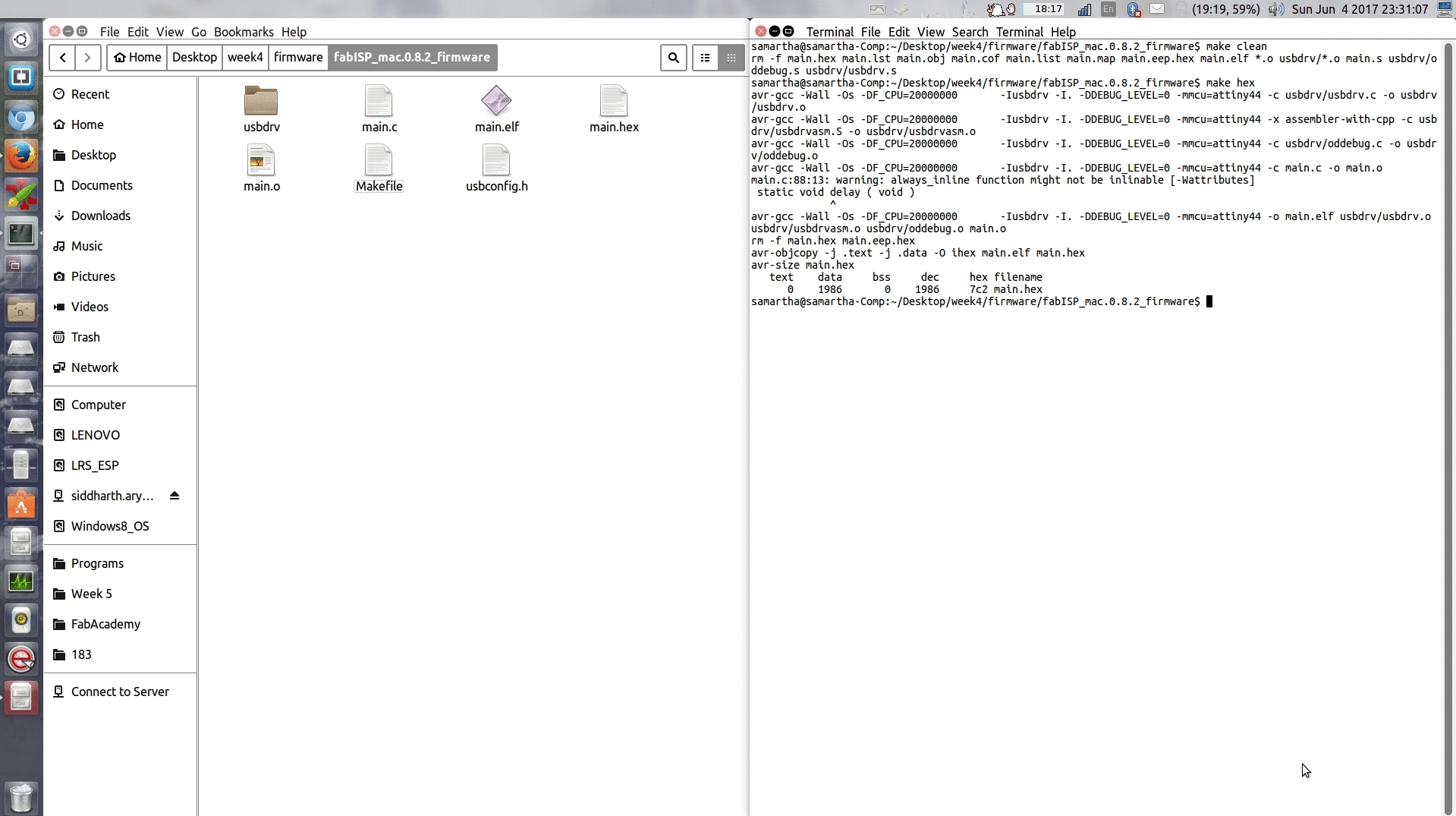
Now, Type: make hex
success!
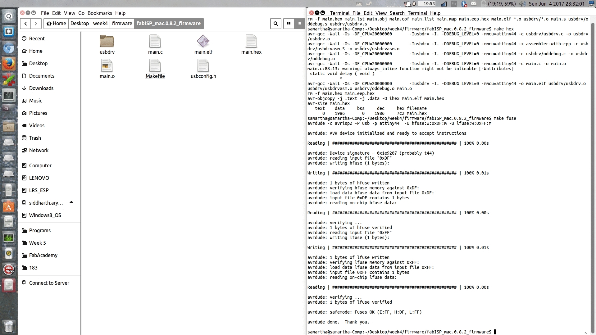
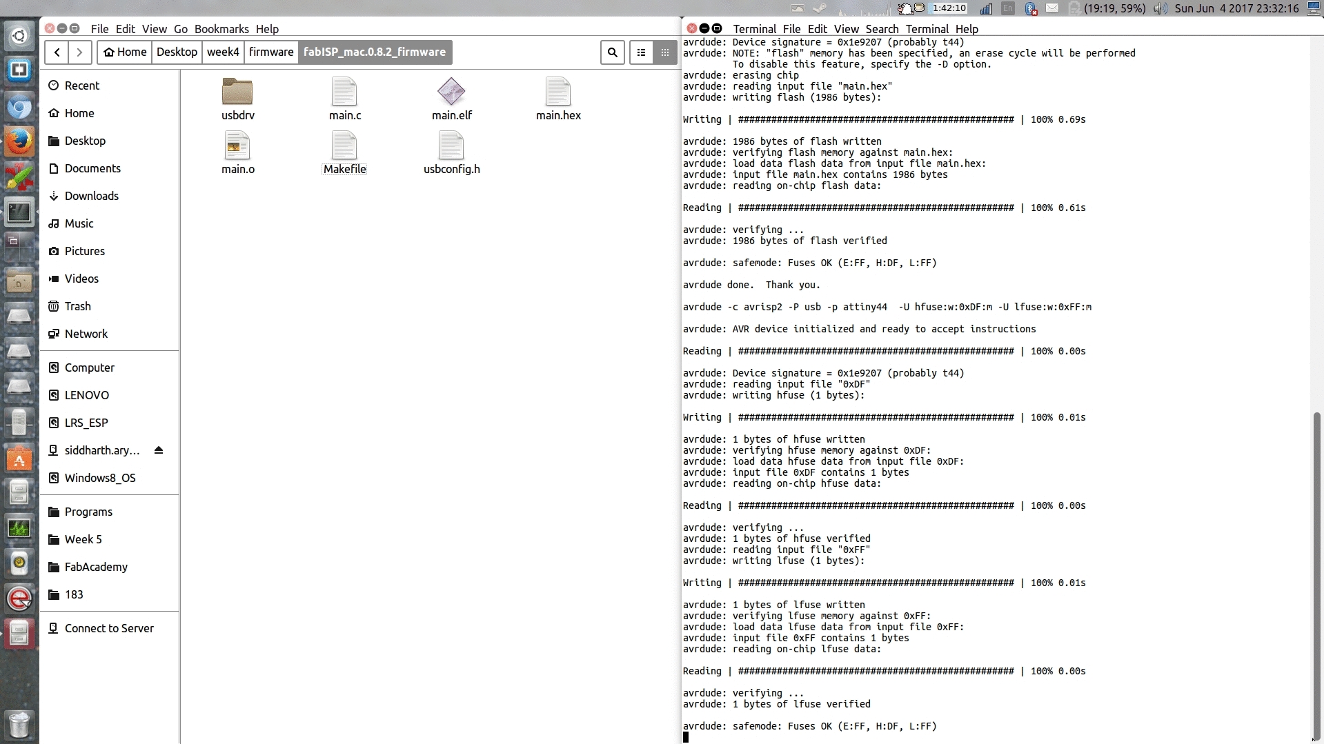
Next, setting up the fuses so that the board will use the external clock (crystal), Type: make fuse
failure....
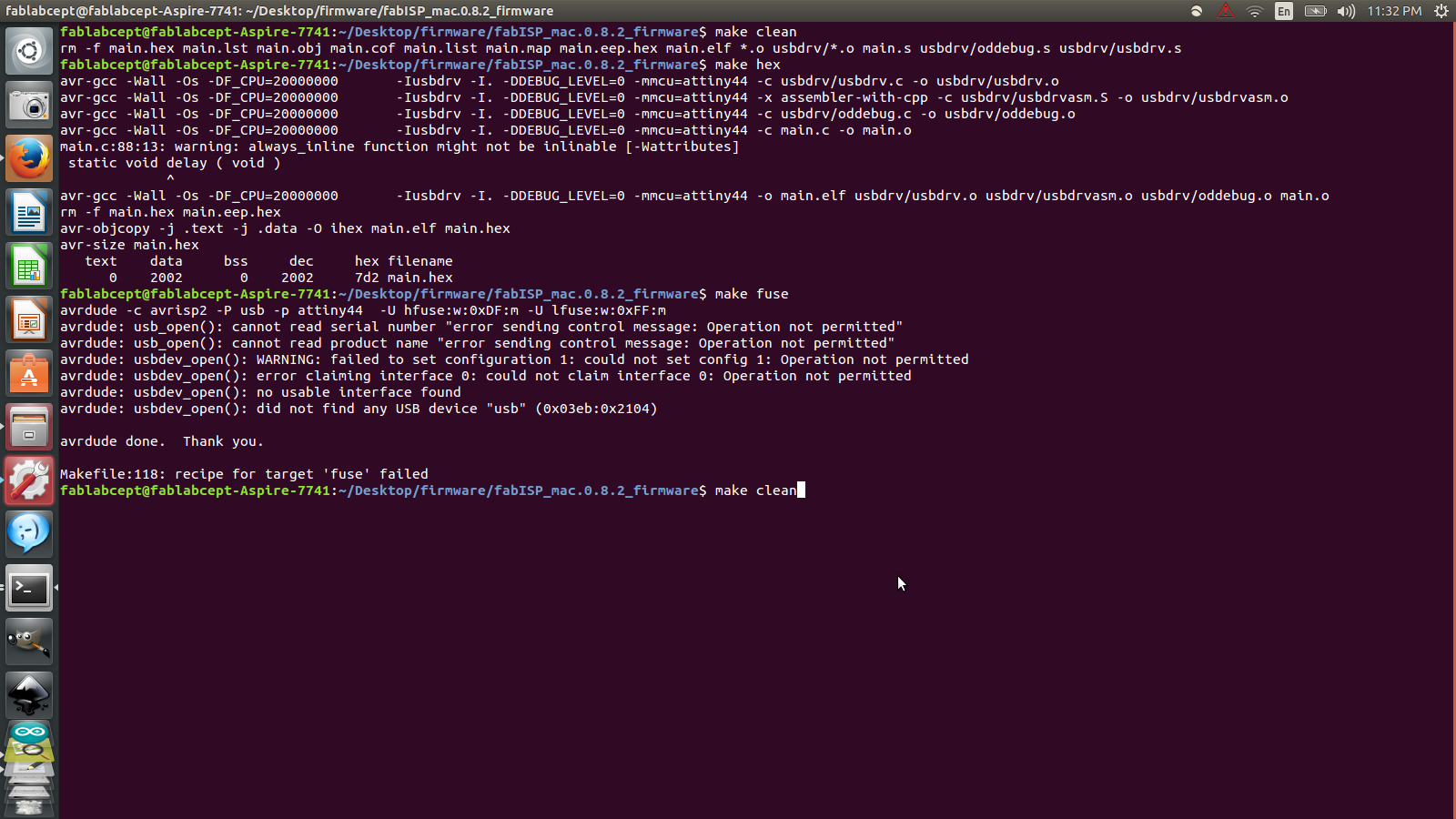
I failed to fuse because one of the usb port of the lab's system was unrecognizable. So I switched to the other system, again Siddharth Arya, fellow student, provided his workstation for programming.
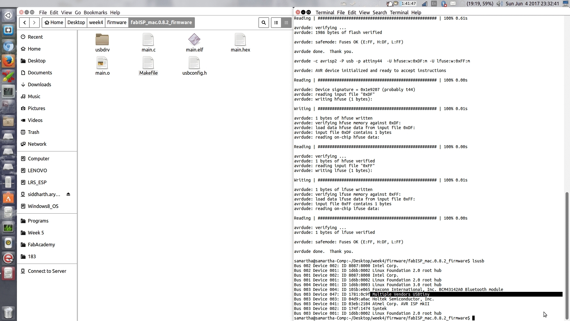
Again, I repeated all the steps- Make Clean, Make Hex and Make Fuse. And then to program the board to be an ISP, I Typed: make program.
Finally, it's a success!
Now to verify that the FabISP is working correctly, I typed lsusb and could see a list of the USB devices plugged into the computer. FabISP is listed like this- Bus 003 Device 047: ID 1781:0c9f Multiple Vendors USBtiny. The text is highlighted in the screenshot , it can also be seen in the below video.
After having programmed the board, I removed the 0 ohm resistor and solder bridge, so that it can be used as a programmer to program other boards. This could be seen in the image below.
Links
Week 4 FilesFabISP: Programming tutorial