- Week 3 +
computer-controlled cutting
Tasks
In this week, we had to do two exercises- Laser Cutting and Vinyl Cutting
- Laser Cutting: Design, make, and document a parametric press-fit construction kit, accounting for the lasercutter kerf, which can be assembled in multple ways. Demonstrate and describe parametric 2D modelling processes involved in using the laser cutter.
- Vinyl Cutting: Learn using a vinyl cutter and demonstrate its usage.
Task 1- Laser Cutting
Step 1: Laser Cutting Test
Trial 1- Firstly, to test the kerf- meaning the loss of material that is removed during laser cutting, we provided following sizes to the notches -1.6mm, 1.8mm and 1.9mm and laser cut them. Our group page for laser cutting exercise can be accessed here for in-depth information about the whole process.
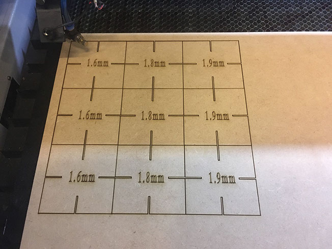
It can be seen in the video below that the sizes we laser cut are either too tight or are too loose. 1.6mm slot is slightly smaller and 1.8mm is larger than what will be an ideal notch width.
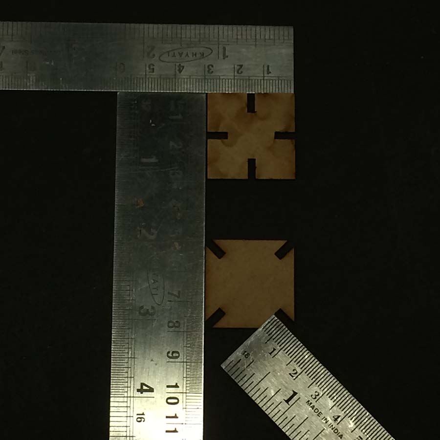
Trial 2- So we changed the notch widths and decided to cut them again between two sizes 1.6mm and 1.8mm. Following image shows the sizes that we laser cut again- 1.7mm and 1.75mm.
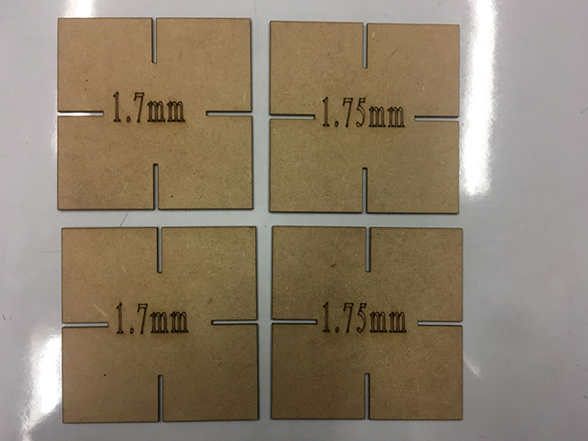
In the video below, our fellow student Chandni is demonstrating the second trial we did. I am recording it, the hand between frame 1:32 to 1:35 is mine :D. Here we are showing that 1.7mm slots fits quite well.
Kerf value for pine MDF that we used for the group assignment is 0.1mm.
Step 2: Non-Prametric Design
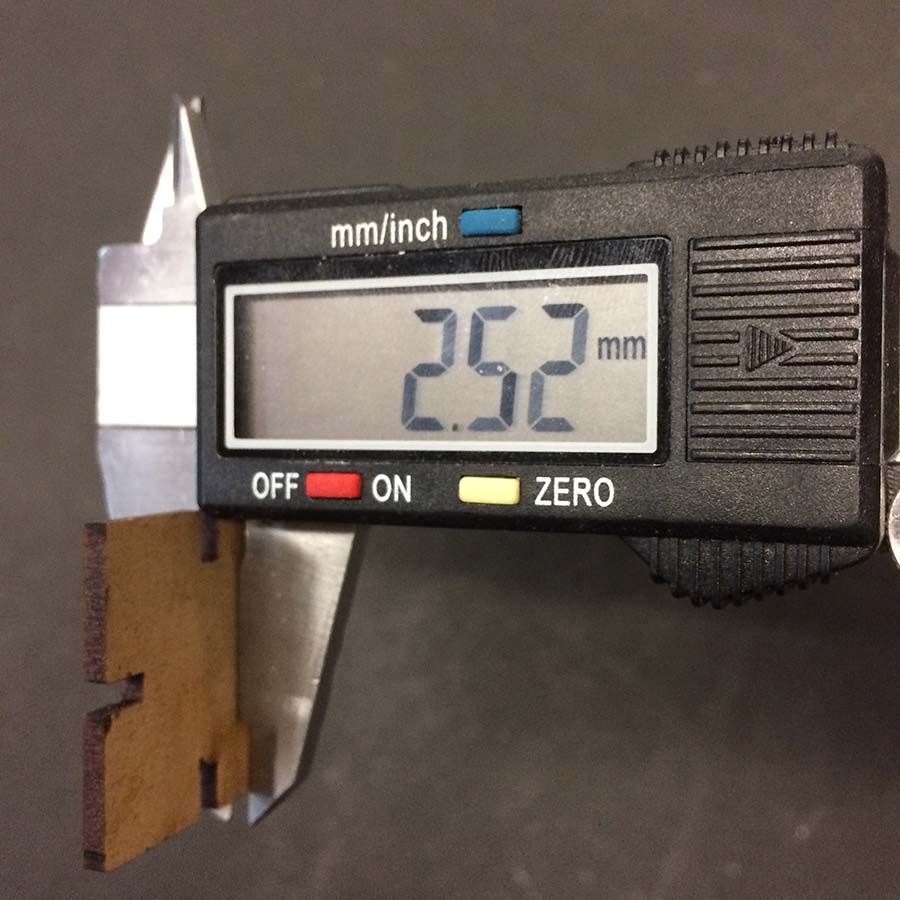
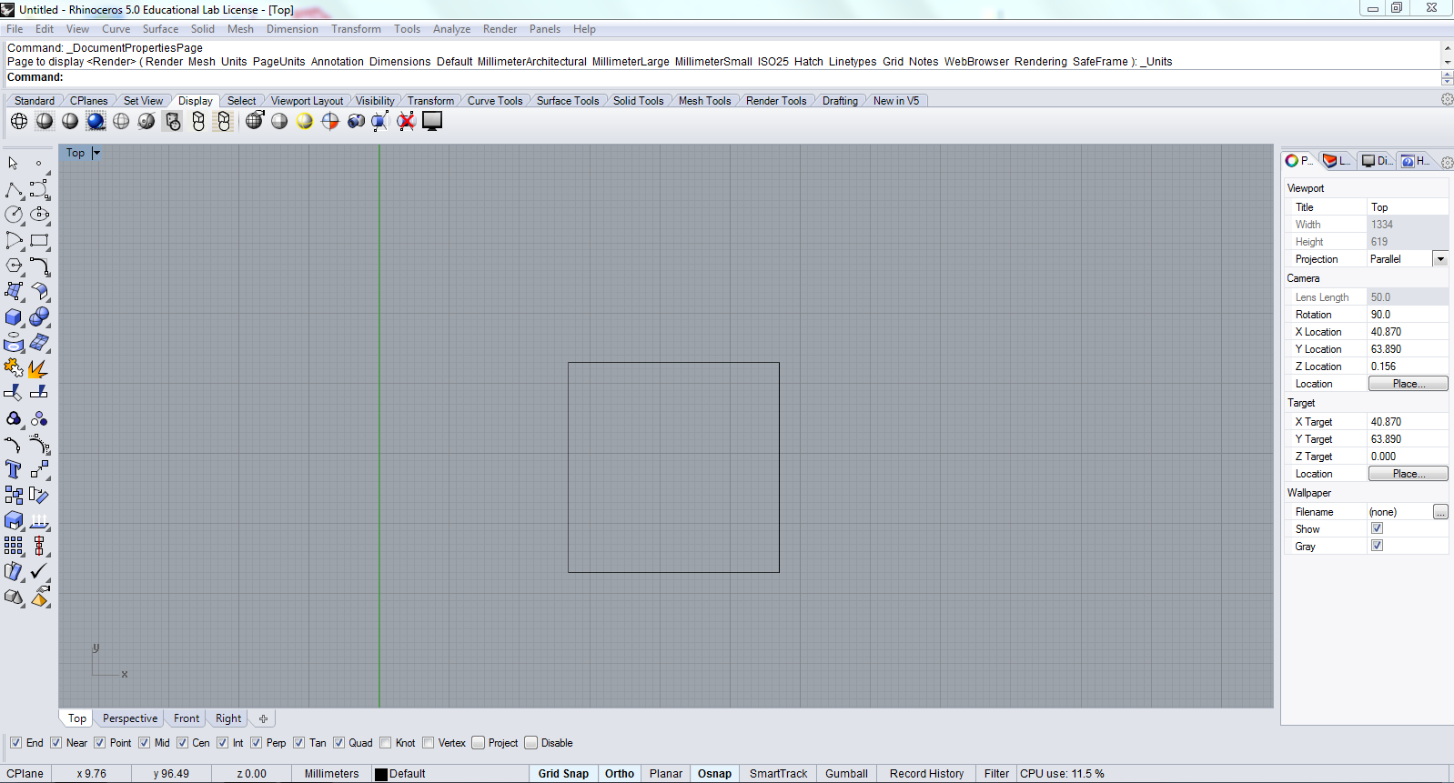
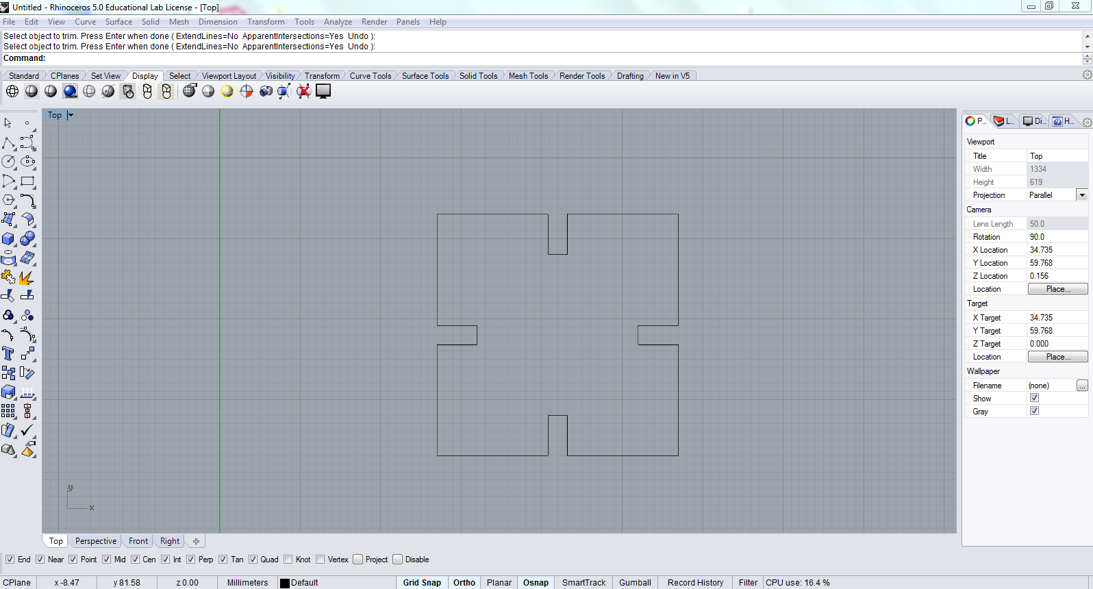
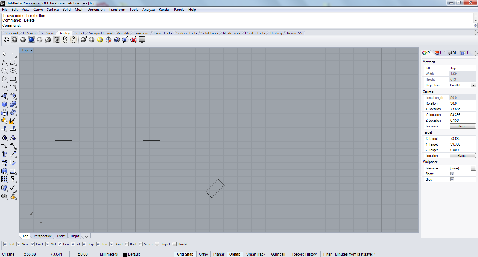
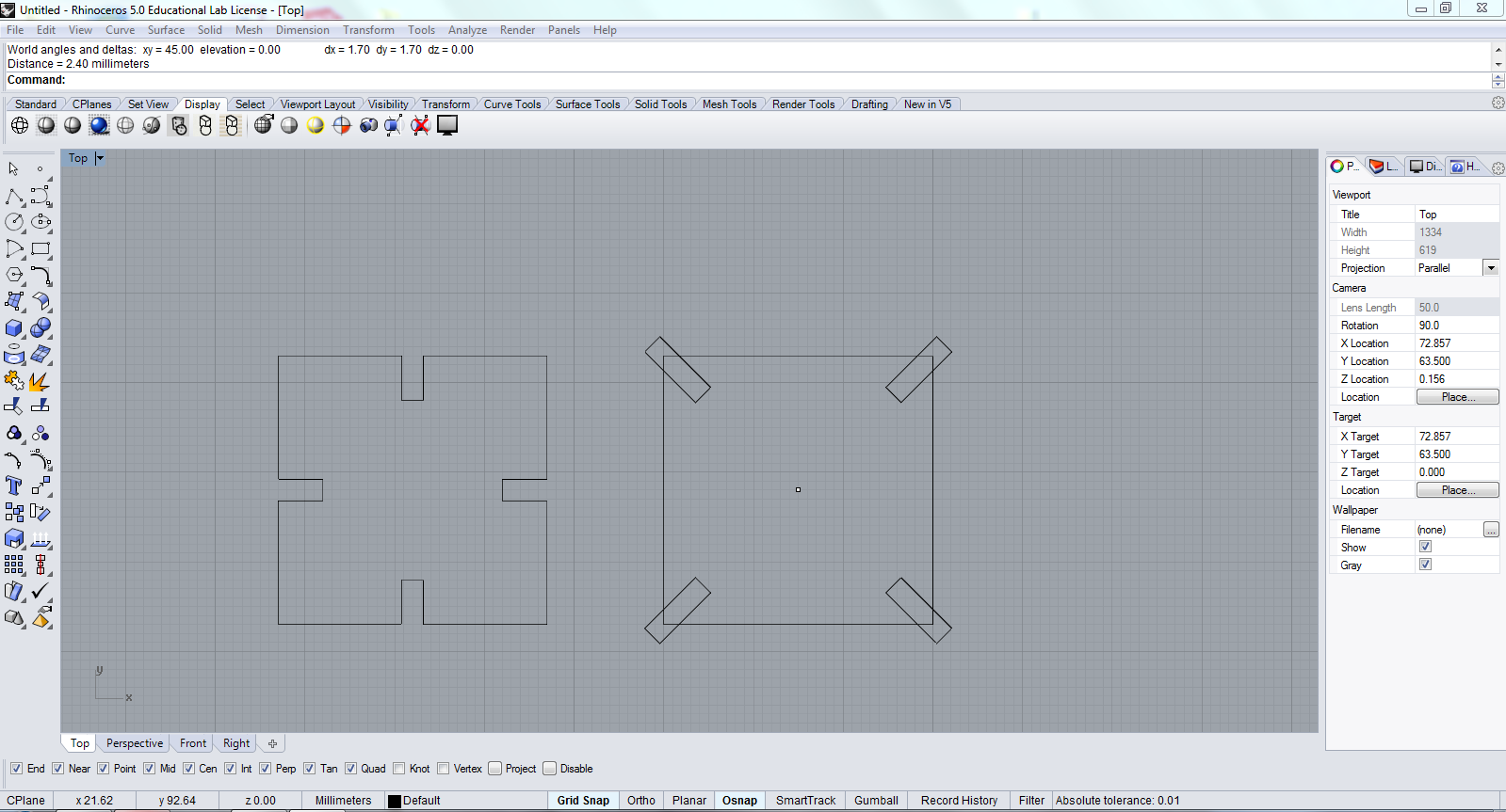
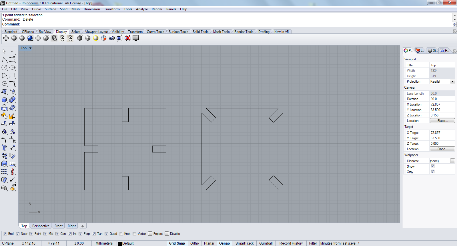
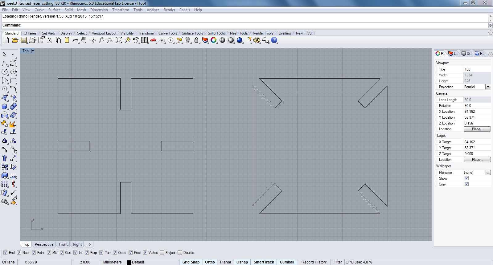
To explore press-fit laser cutting exercise, I thought of exploring square geometry with notches at mid-points and at vertices. I kept the size of the square and depth of the overlap of the notch same. This would allow me to see how many permutation and combinations are possible with few variants. The thickness of the MDF I am using is 2.52 mm. Following screenshots and photographs explain the process of designing in Rhino and test cut as well as final cut.
Step 3: RDWorks and Cutting
I used RDWorks program to perform laser cutting operation on medium format laser cutter manufactured be Sil.

RDWorks is fairly a very simple and easy program to master. To do the job, I opened the program and imported the .dxf file that needs to be cut.
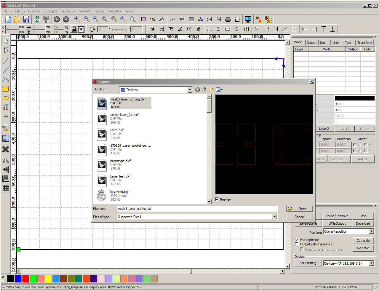
This is how it looks like when I opened it. Red is the default color in which the drawing generally appears.
RDWorks gives you an opportunity to some tweaking with the original file, like changing the sizes, multiplying number the of objects to be cut and also creating some basic 2D geometry.
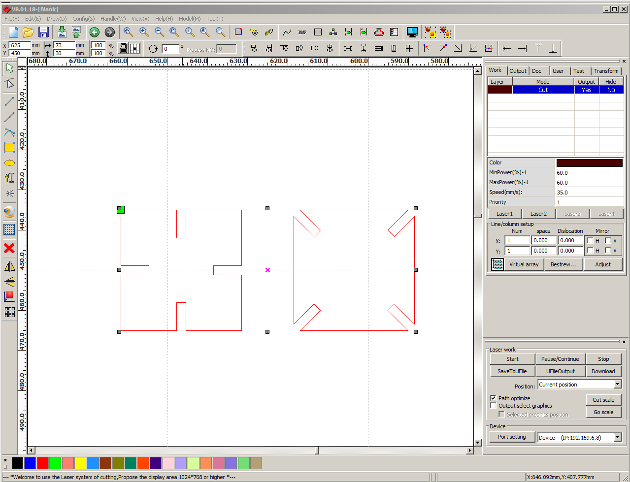
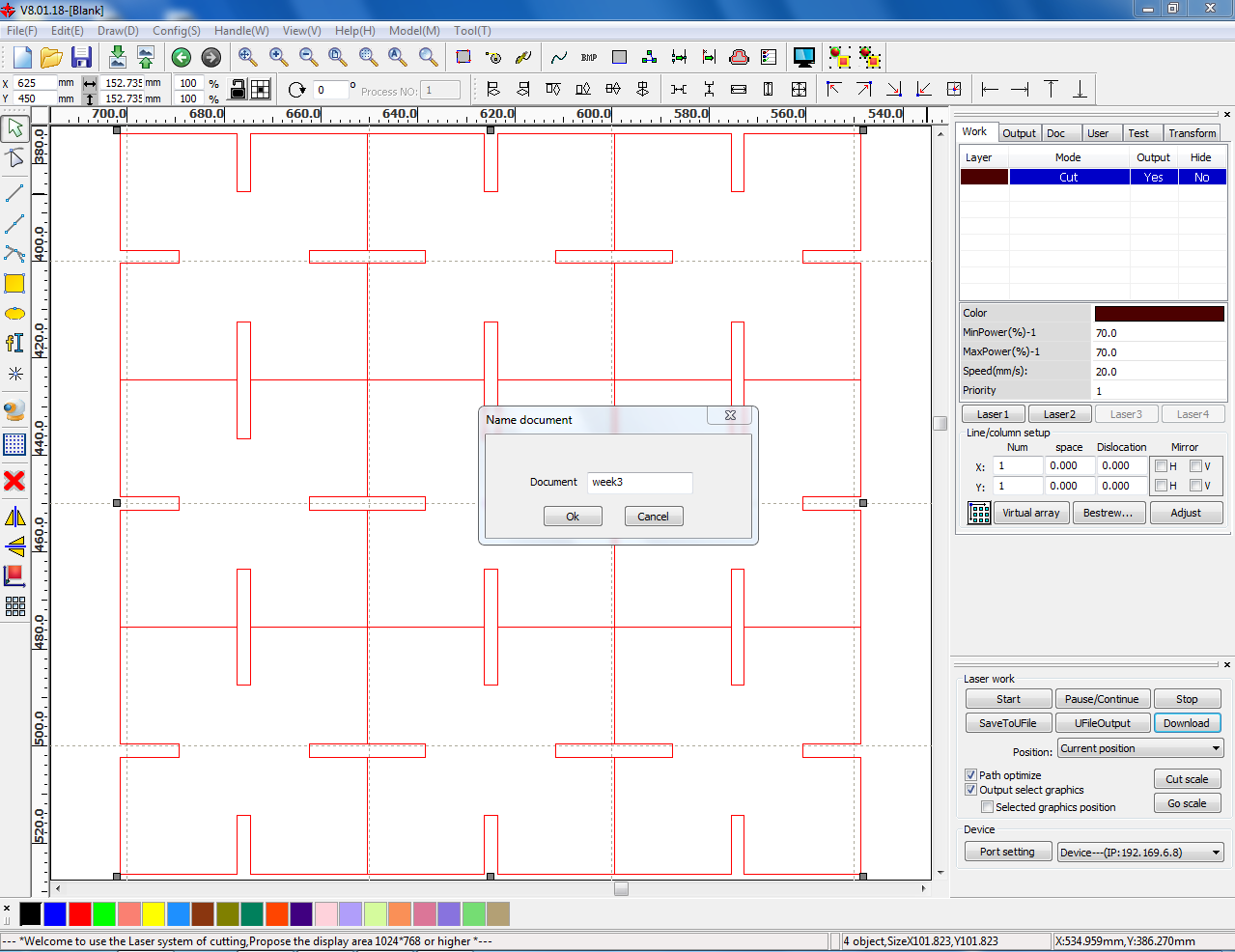
So taking advantage of its interface, I created multiple copies of my design in the program itself. Then I selected following parameters for laser cutting:
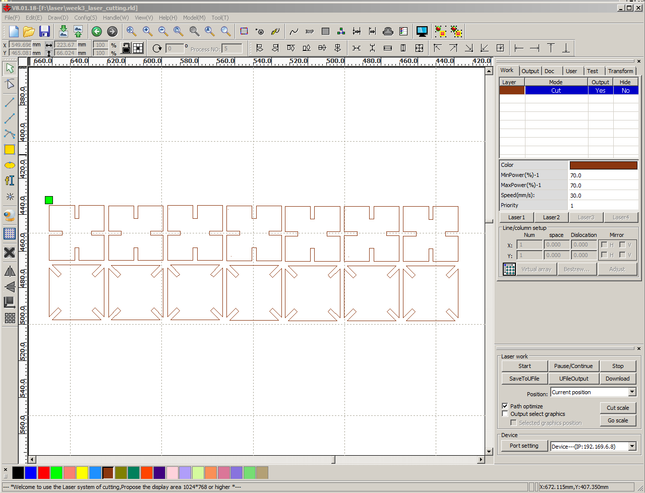
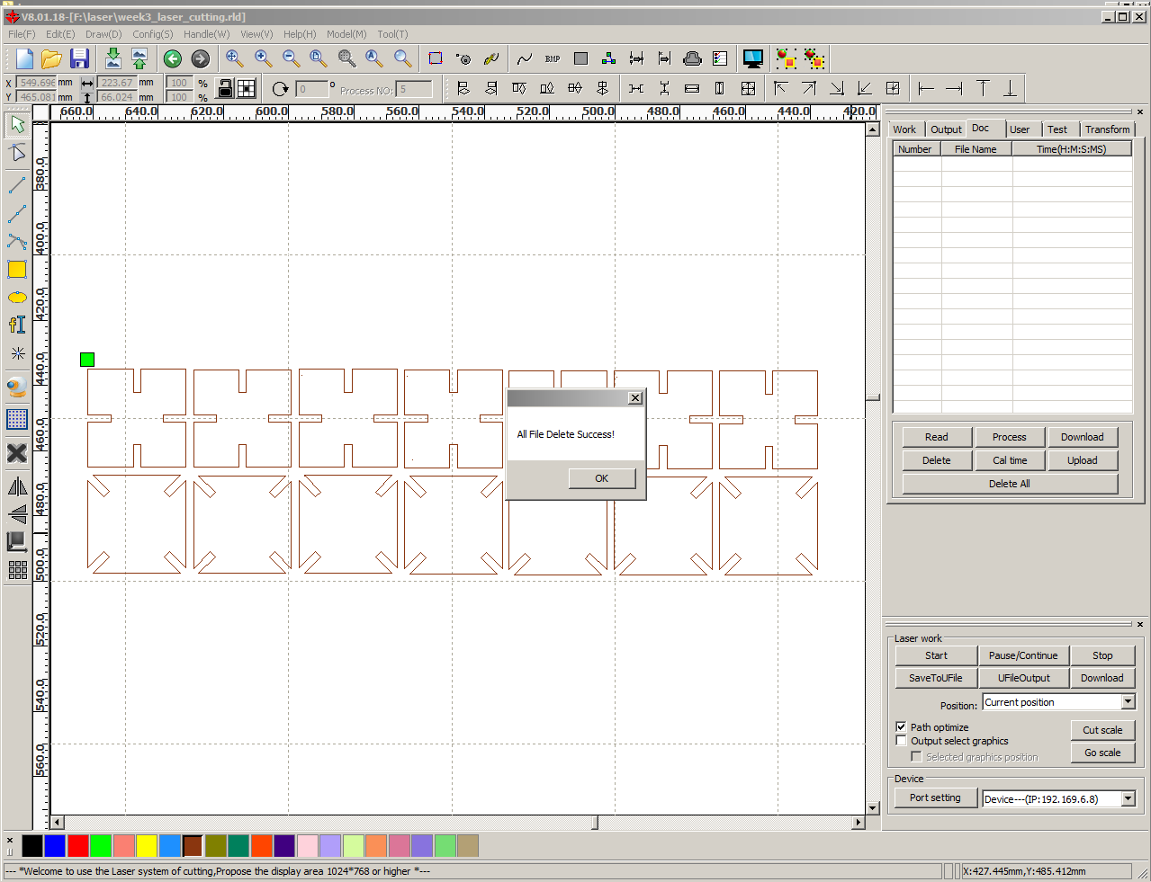
I also changed the layer color to brown. Though there is no necessity to change the color in my project, but it can be a useful tool if one needs to prioritize the cutting sequence. In that case layers are given different colors and the cutting happens in that sequence. Then I went into 'Doc' tab and deleted all previous jobs.
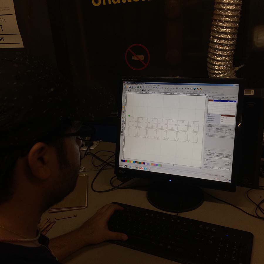
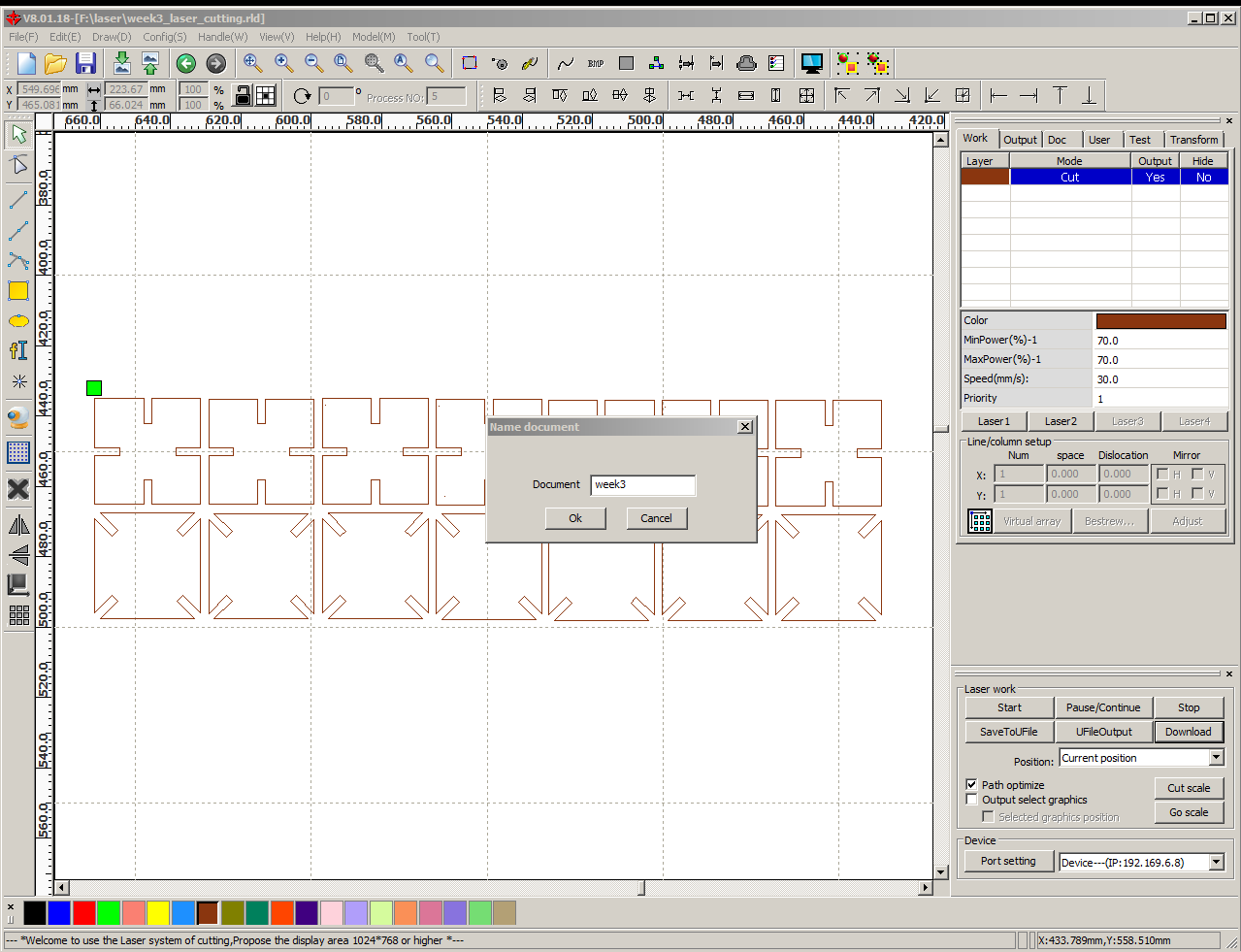
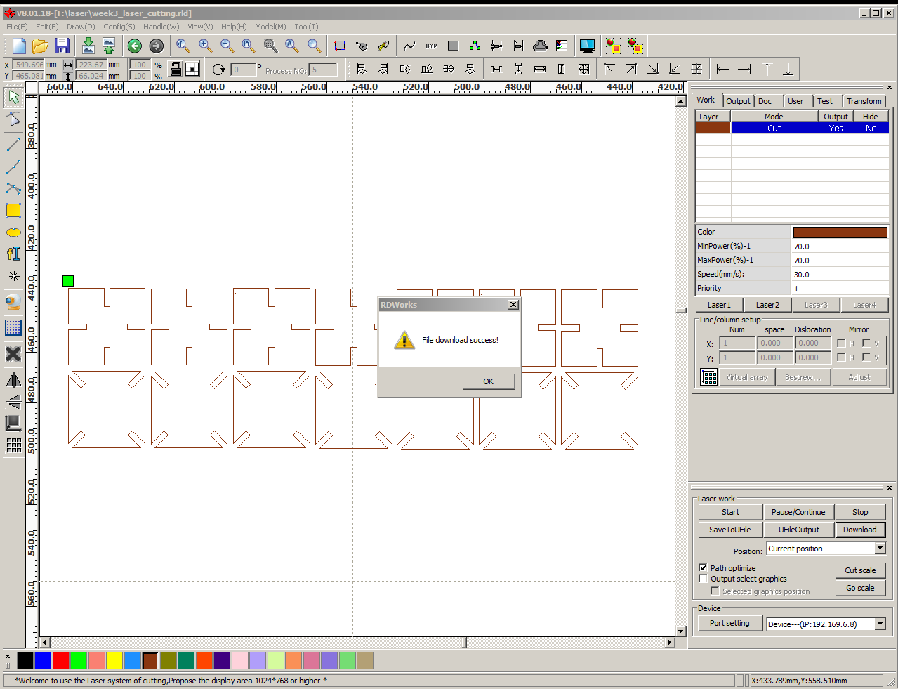
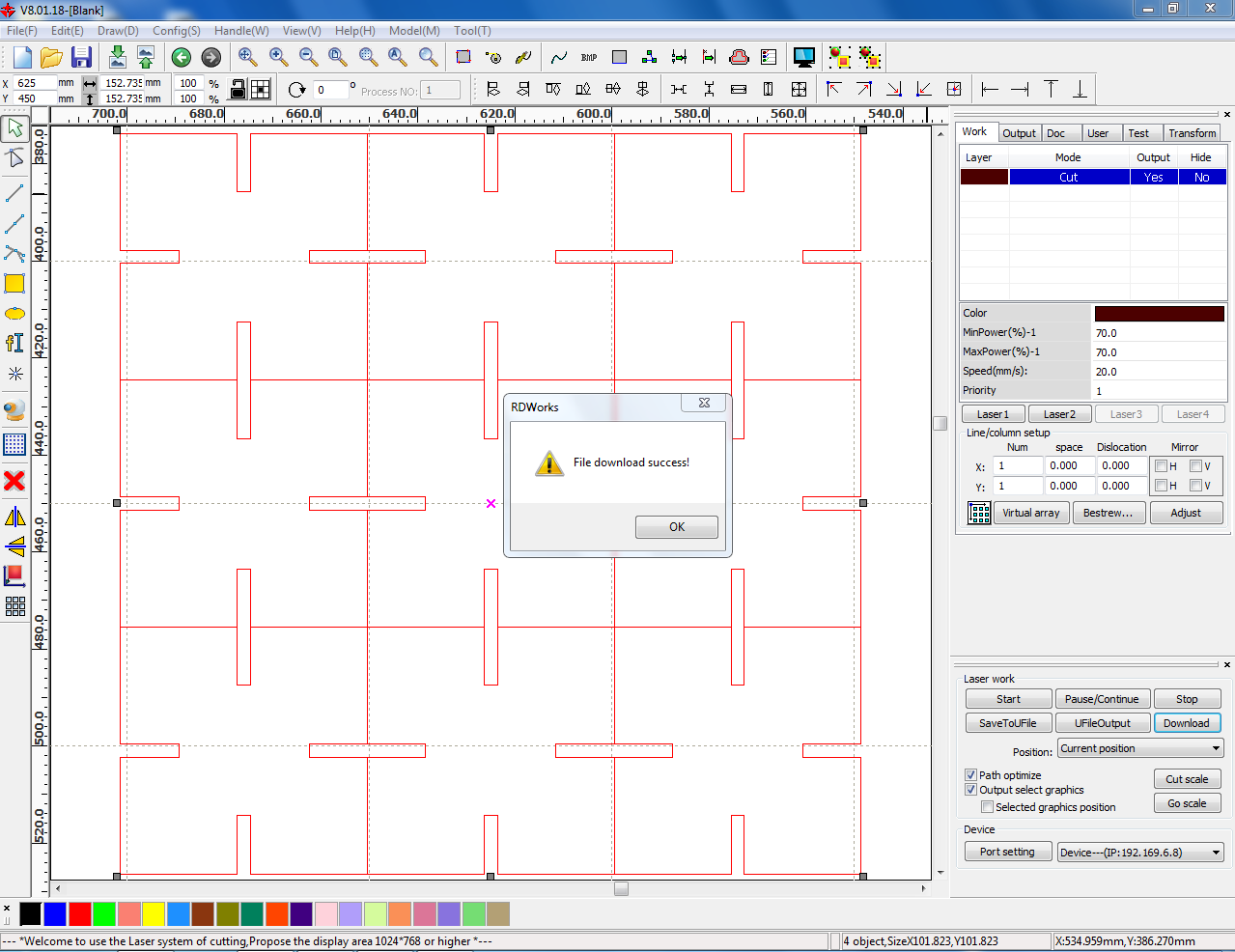
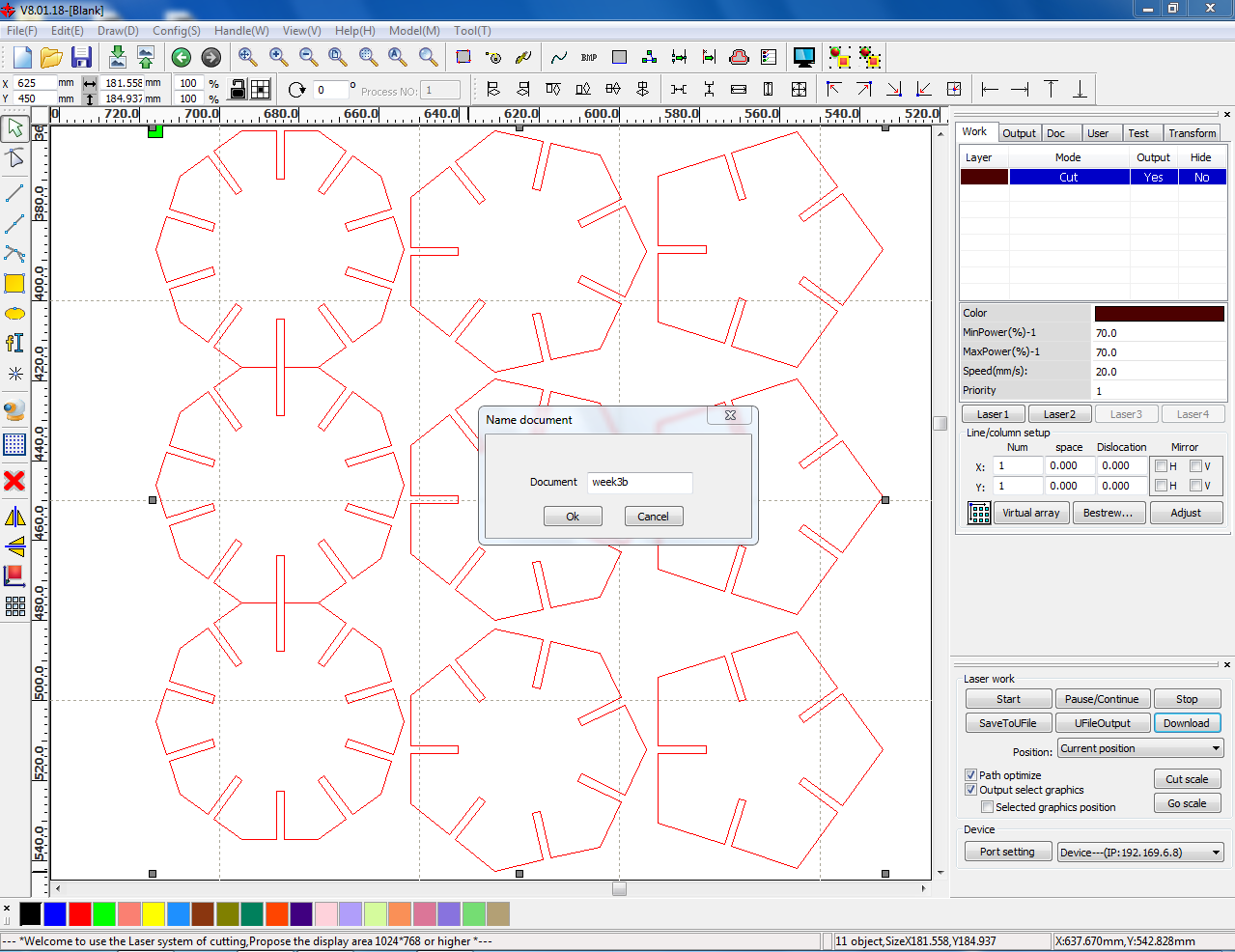
Now to send the cutting file to the laser cutter, I clicked on the download tab and saved it as week3. Now this name will appear on the DSP control system attached on the laser cutter.
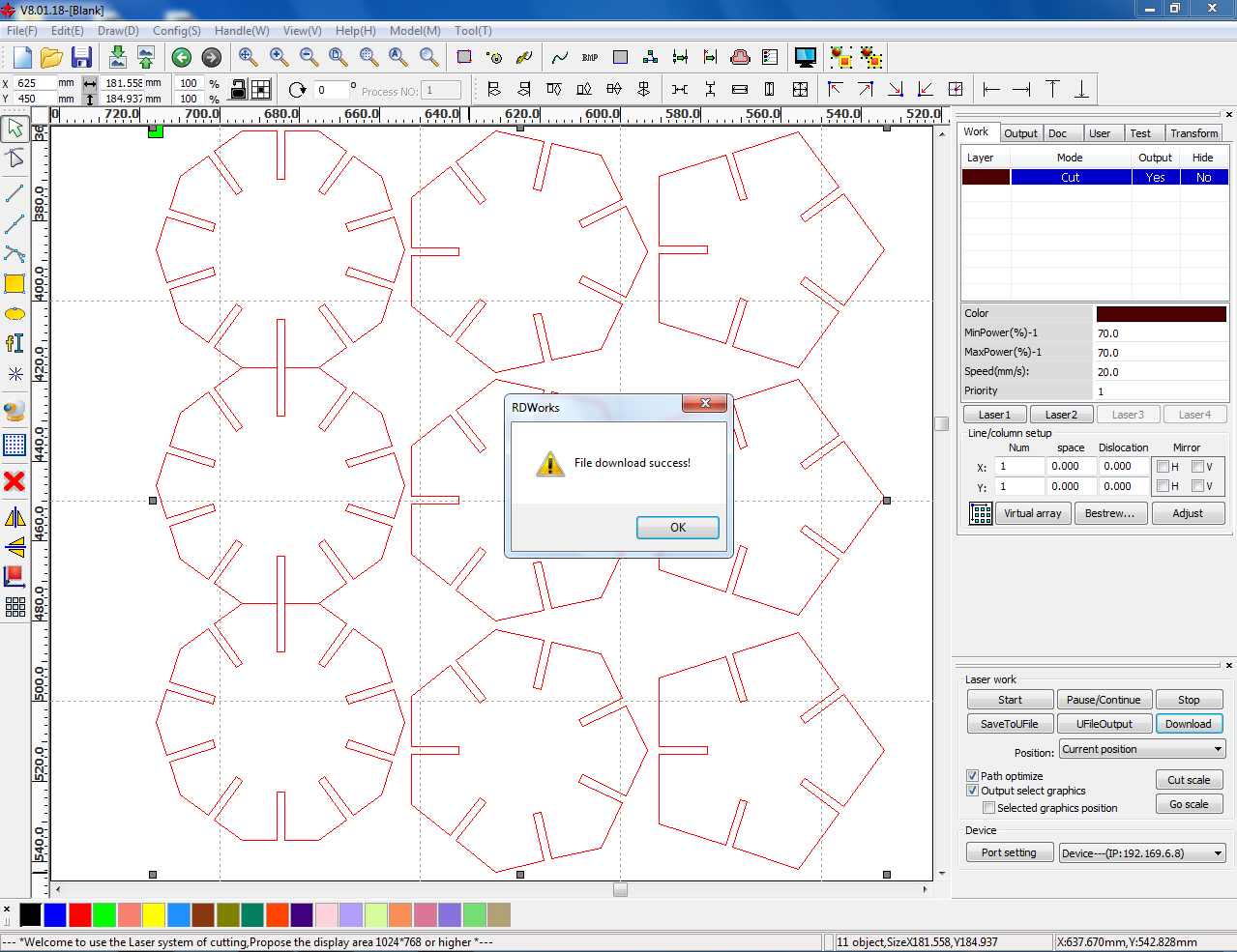
File download Success!
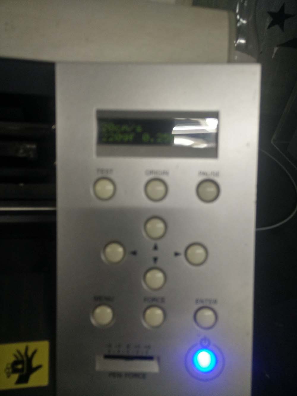
Here, on DSP control system screen the downloaded file can be seen.
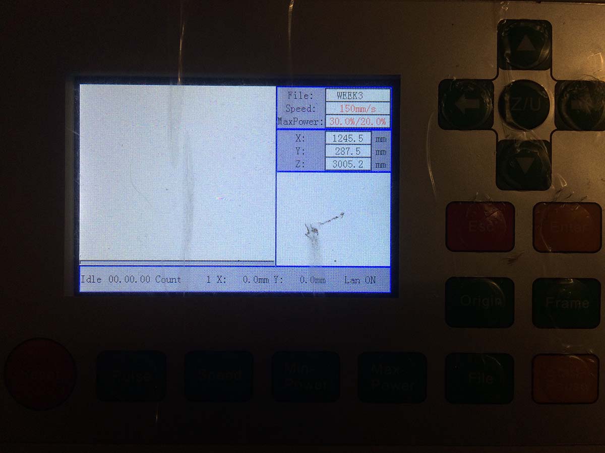
Then I adjusted the depth of focus for the laser cutting operation.
Then I selected the file and hit on the enter button. So here I can see the actual profile on screen that is going to be laser cut.
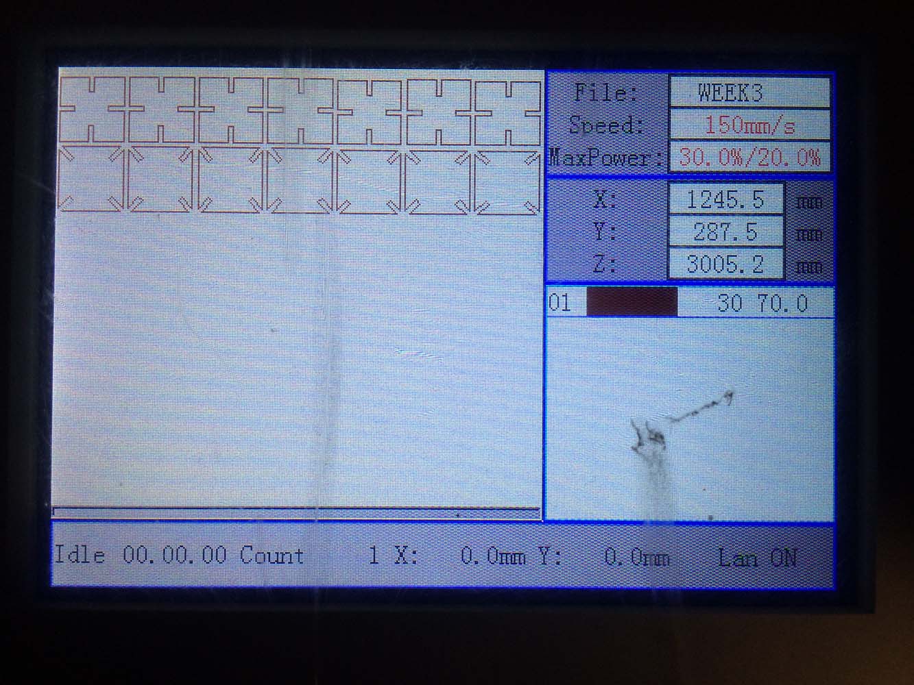
Now once the file is vissible on the screen, using arrows I positioned the laser head. And hit on the origin button to set the origin of cutting. Now to know the origin of the file, one can check for the green colored square box next to 2D profile in RDWorks. This is helpful to set the frame for cutting.
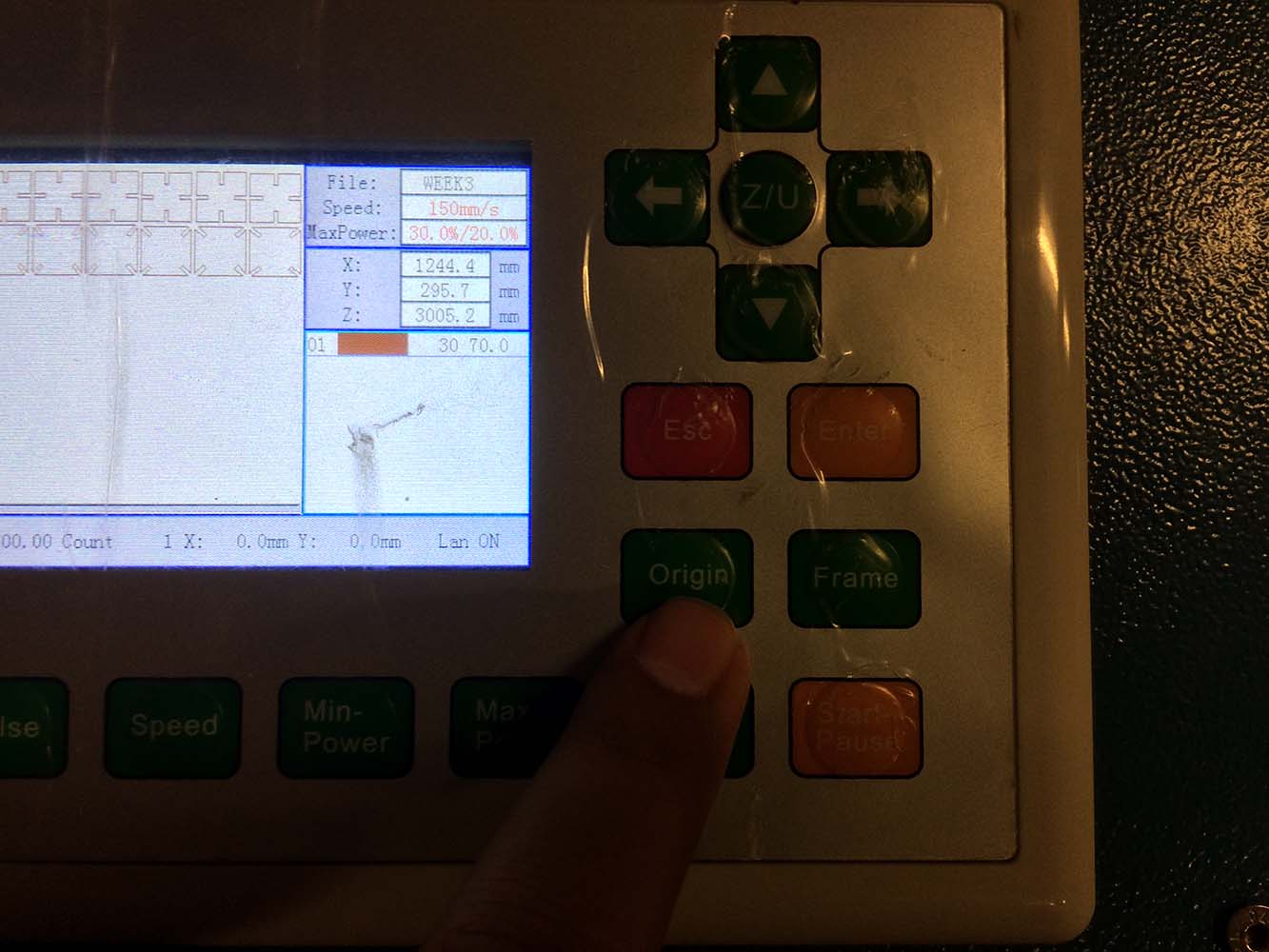
And then by hitting the frame button I ensured that the operation doesn't exceeds the material boundary.
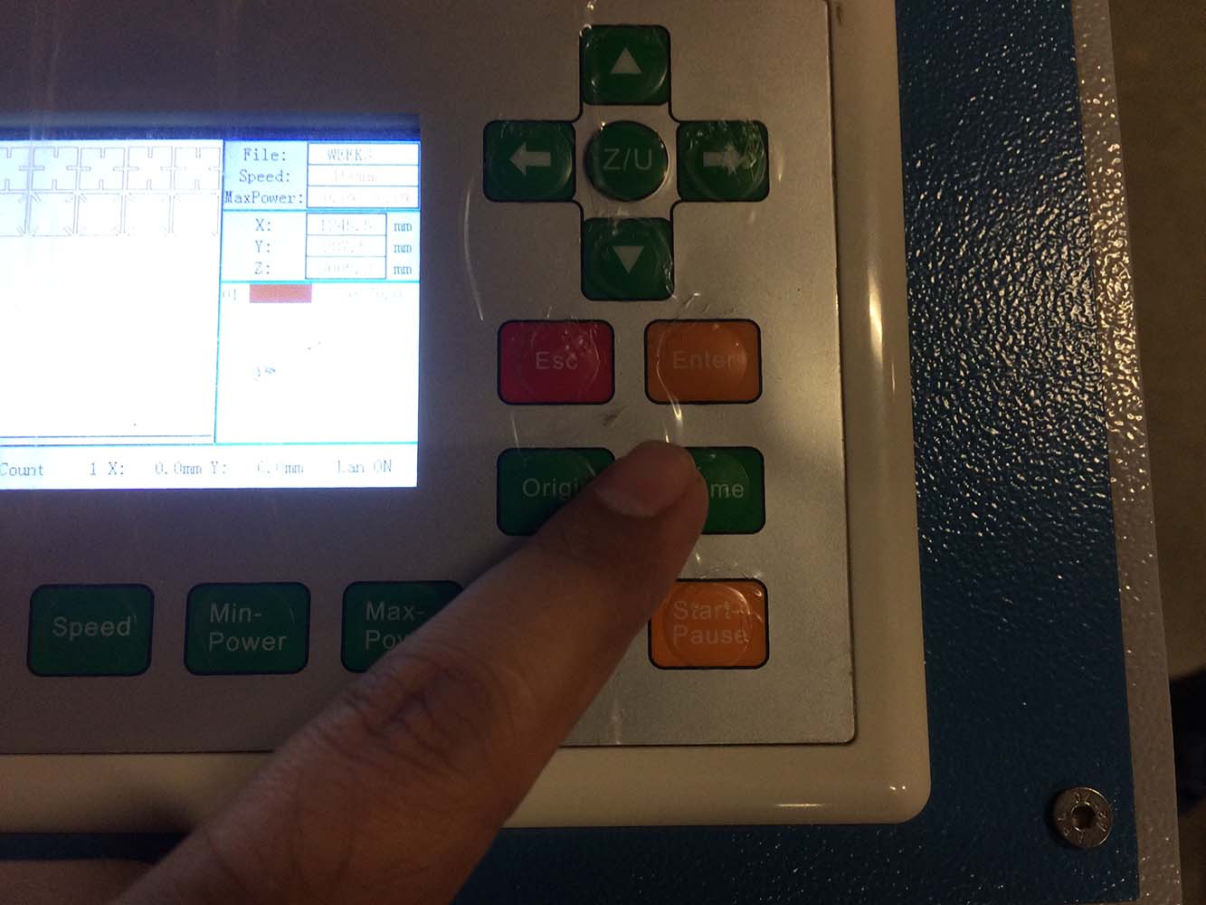
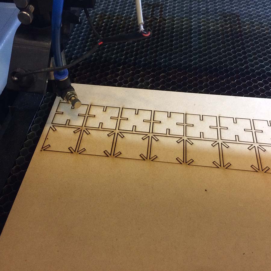
Then I pressed the start button to initiate the laser cutting operation. Following image shows the laser cutting happened successfully.
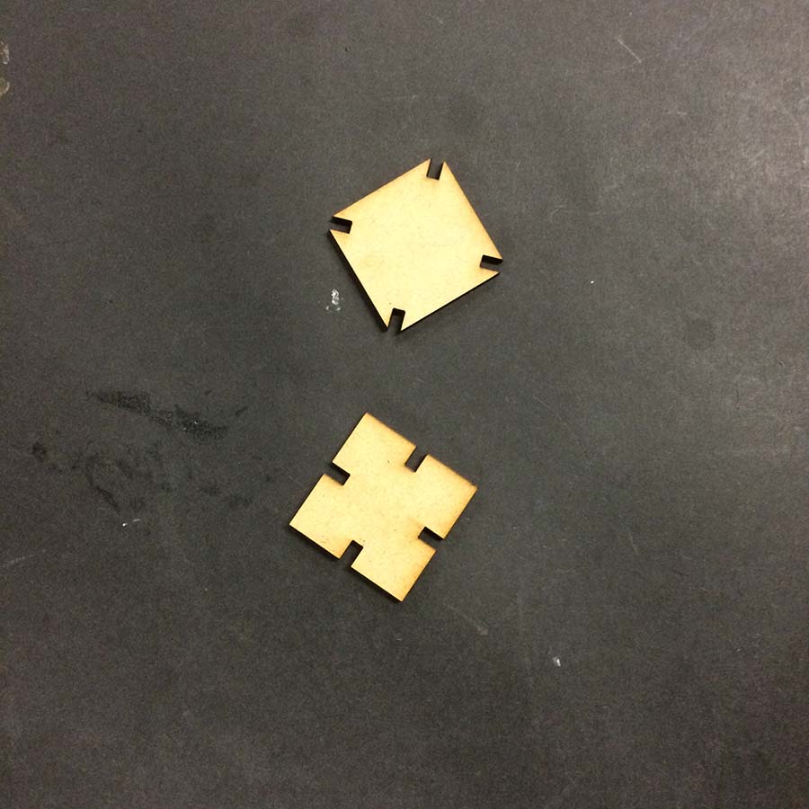
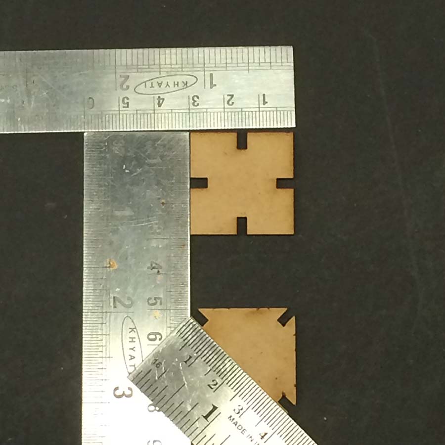
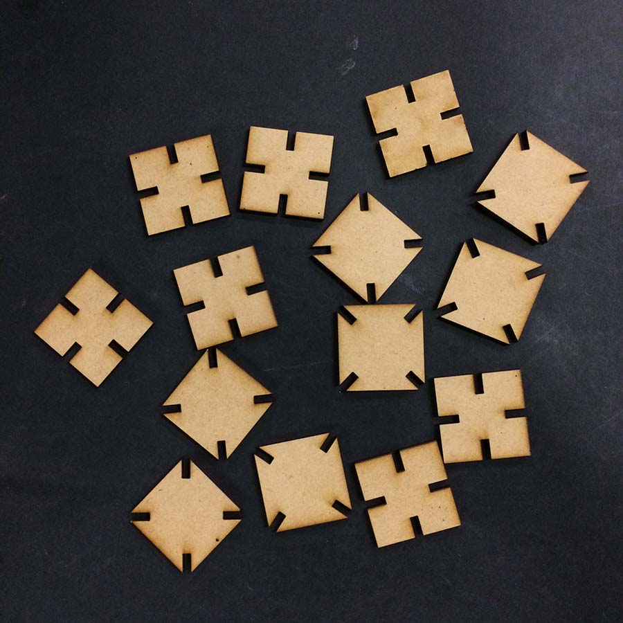
Then I took them off the machine, separated the cut parts and took this photograph.
Step 4: Prametric Design
I am using Grasshopper, a plugin for parametric design in Rhino for creating press-fit construction kit. To get started with grasshopper and learn basics of its canvas and interface, I watched following video and many more in continuation to it on the same channel. Fellow student Arpi Maheshwari also gave me valuable inputs whenever I needed them.
Following steps where taken to create parametric press-fit construction kit:
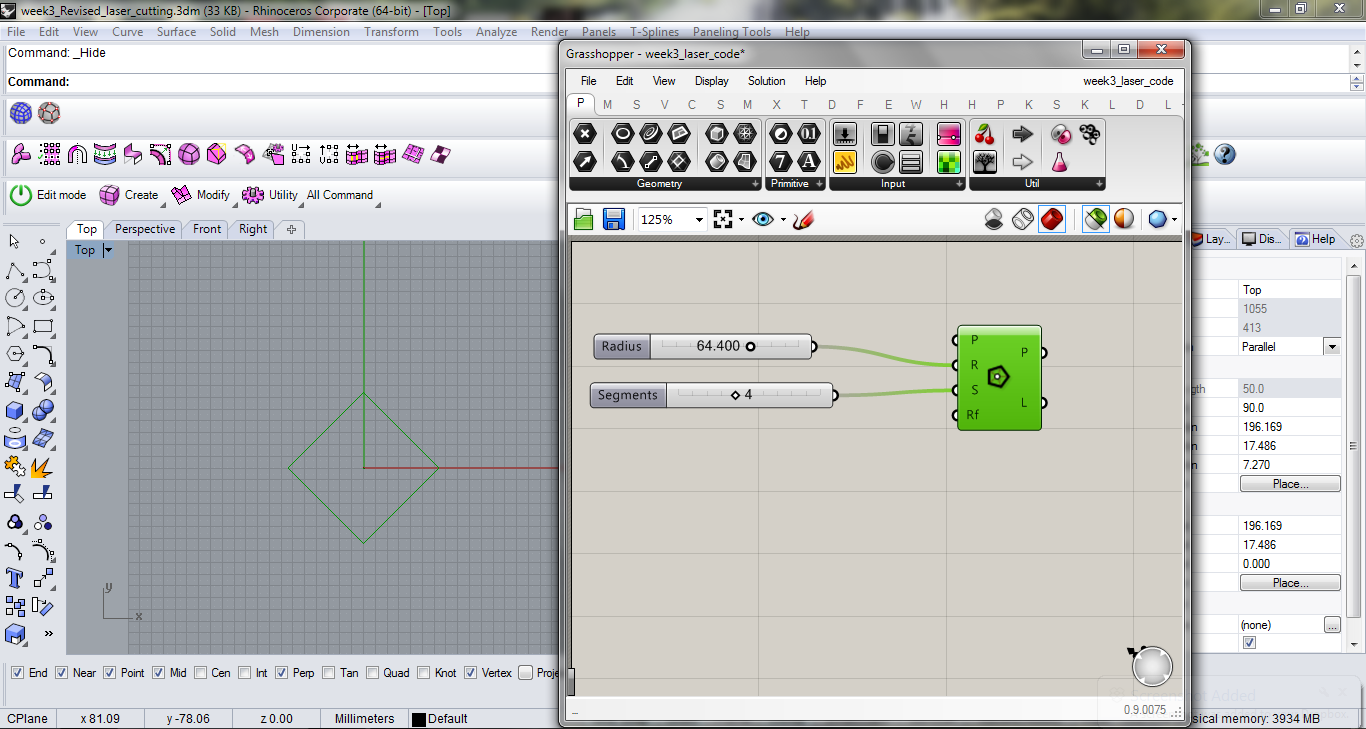
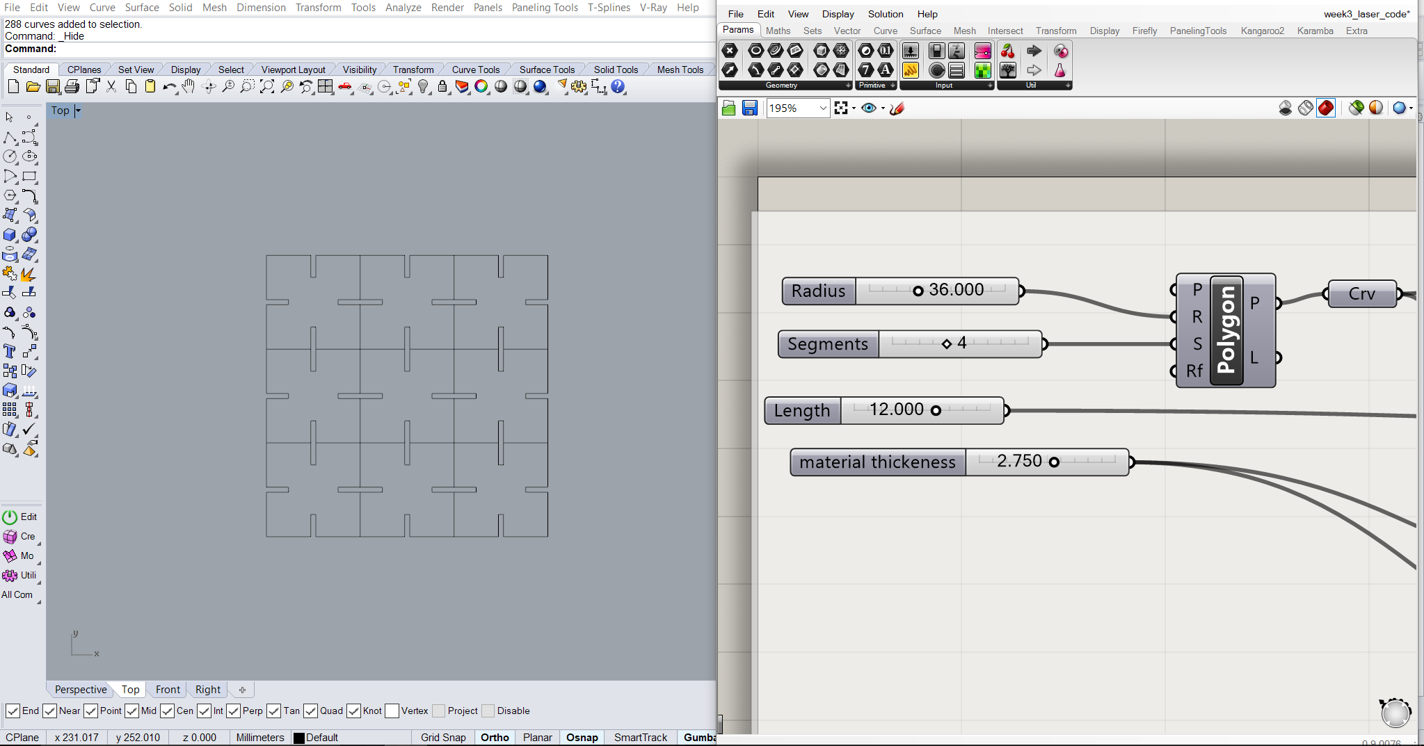
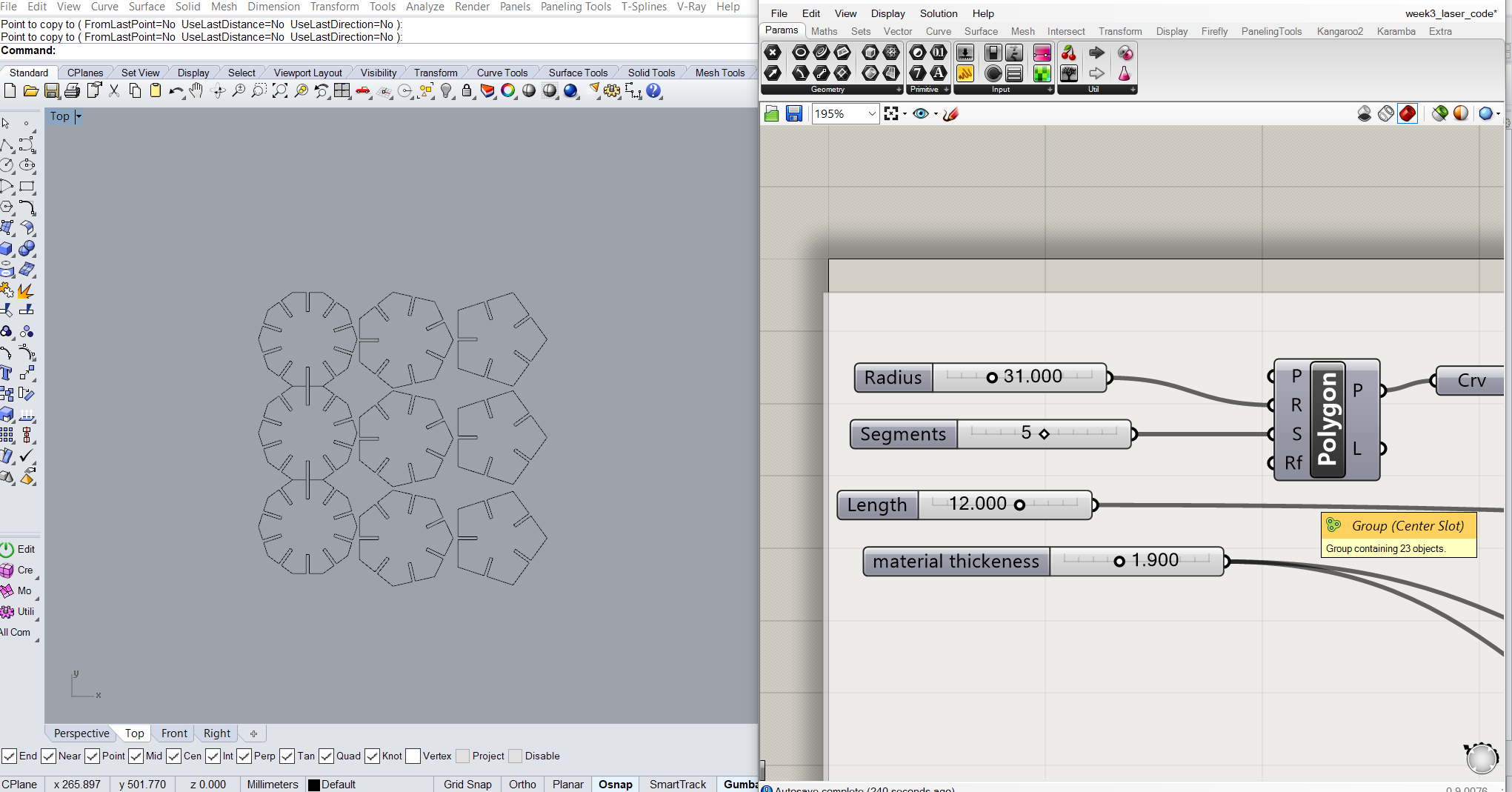
1. To use any component in rhino, directly double click on the canvas and start typing the command you want to use. I began with using polygon command.
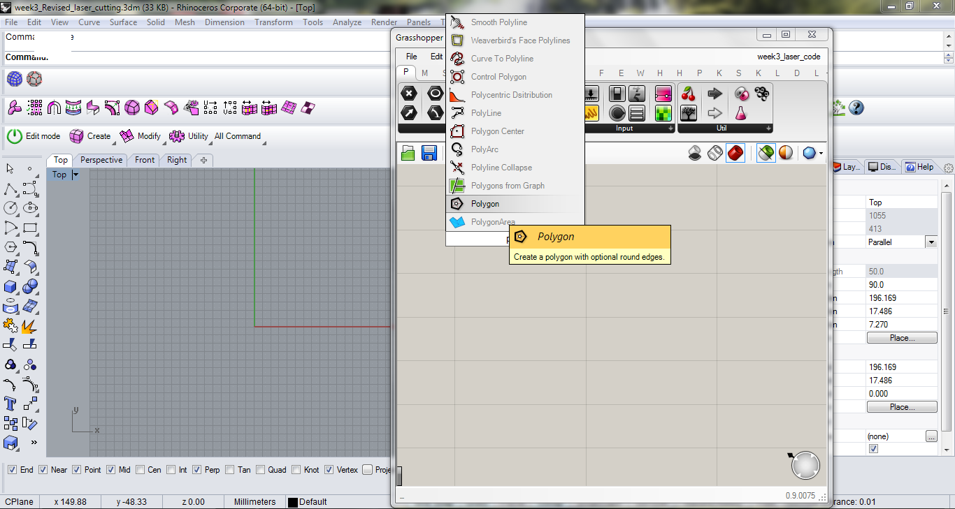
2. For polygon command, I explored two parameters, one radius and the other number of sides.
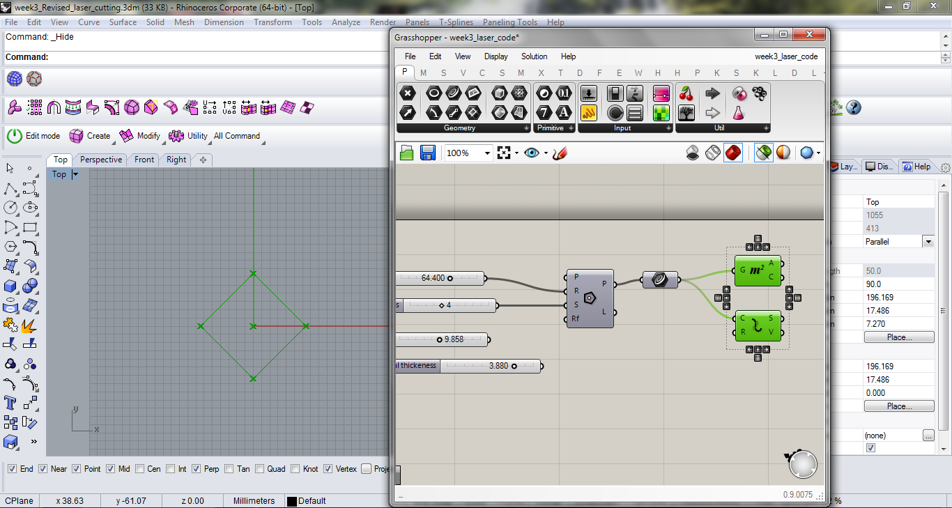
3. Next was to find the vertices and centroid. I used "area" component to get the centroid and explode command to get the sides of the polygon.
4. To obtain centre of each sides, I used "point on curve" and used the value of 0.5 . Next I made a line from each of these points to the centre of the polygon using "S -start point" , "D- direction" and "L- length".
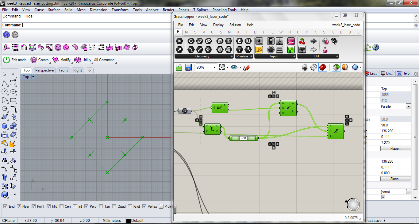
5. Next step is to give "offset" on both the sides, this offset is determined by the thickness of the material and can be changed accordingly.
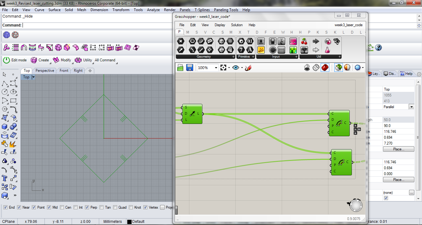
6. Next I joined all the curves and used "Region Difference" to obtain my final geometry of a polygon with slits.
7. Similarly I made another script for polygon with slits at the corners.
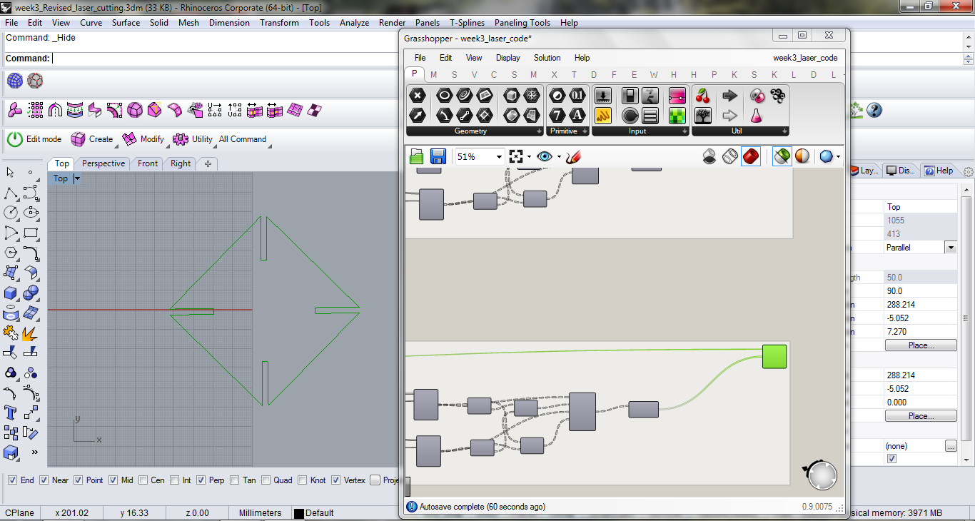
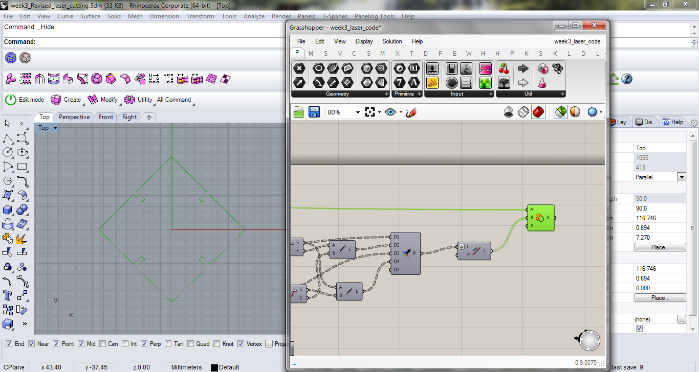
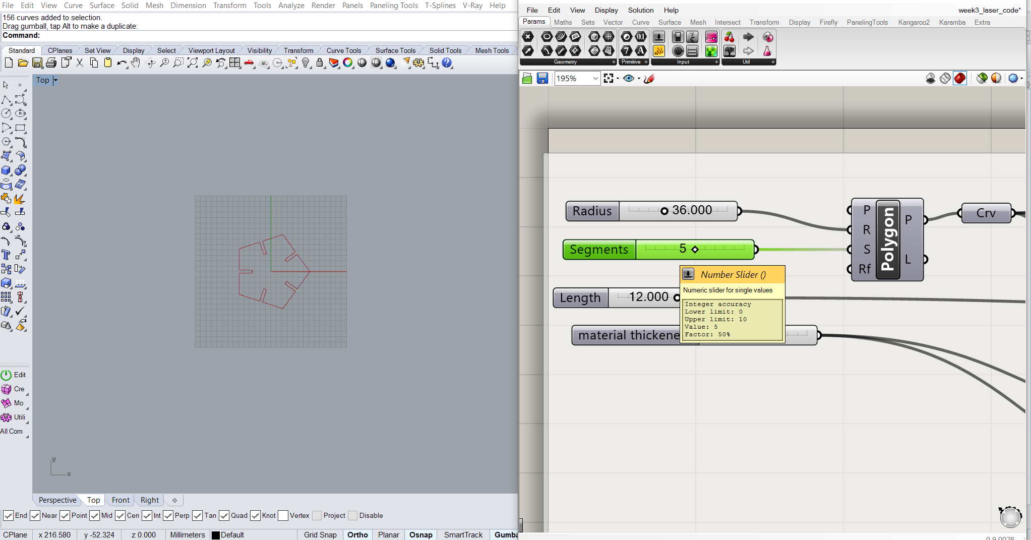
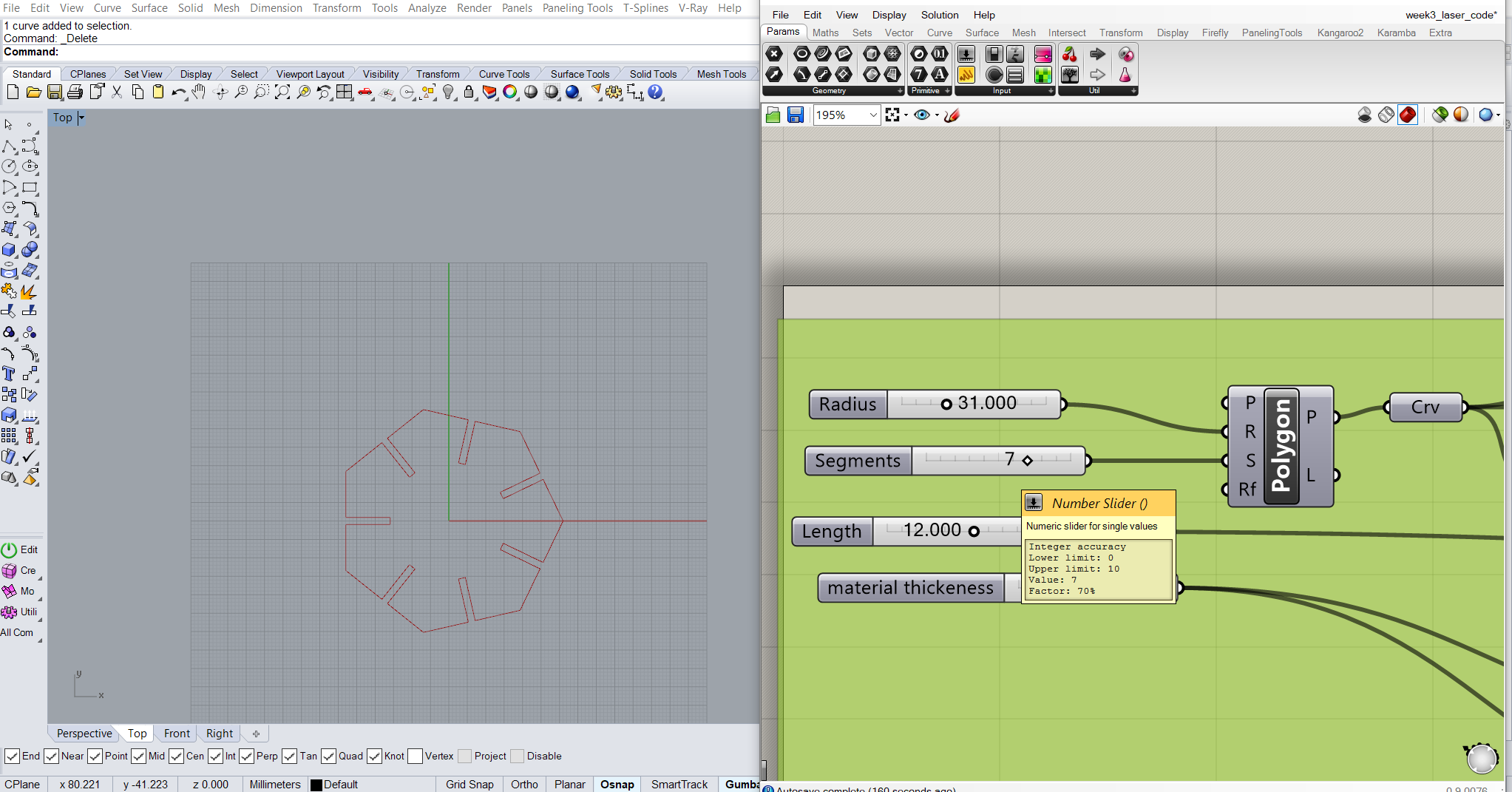
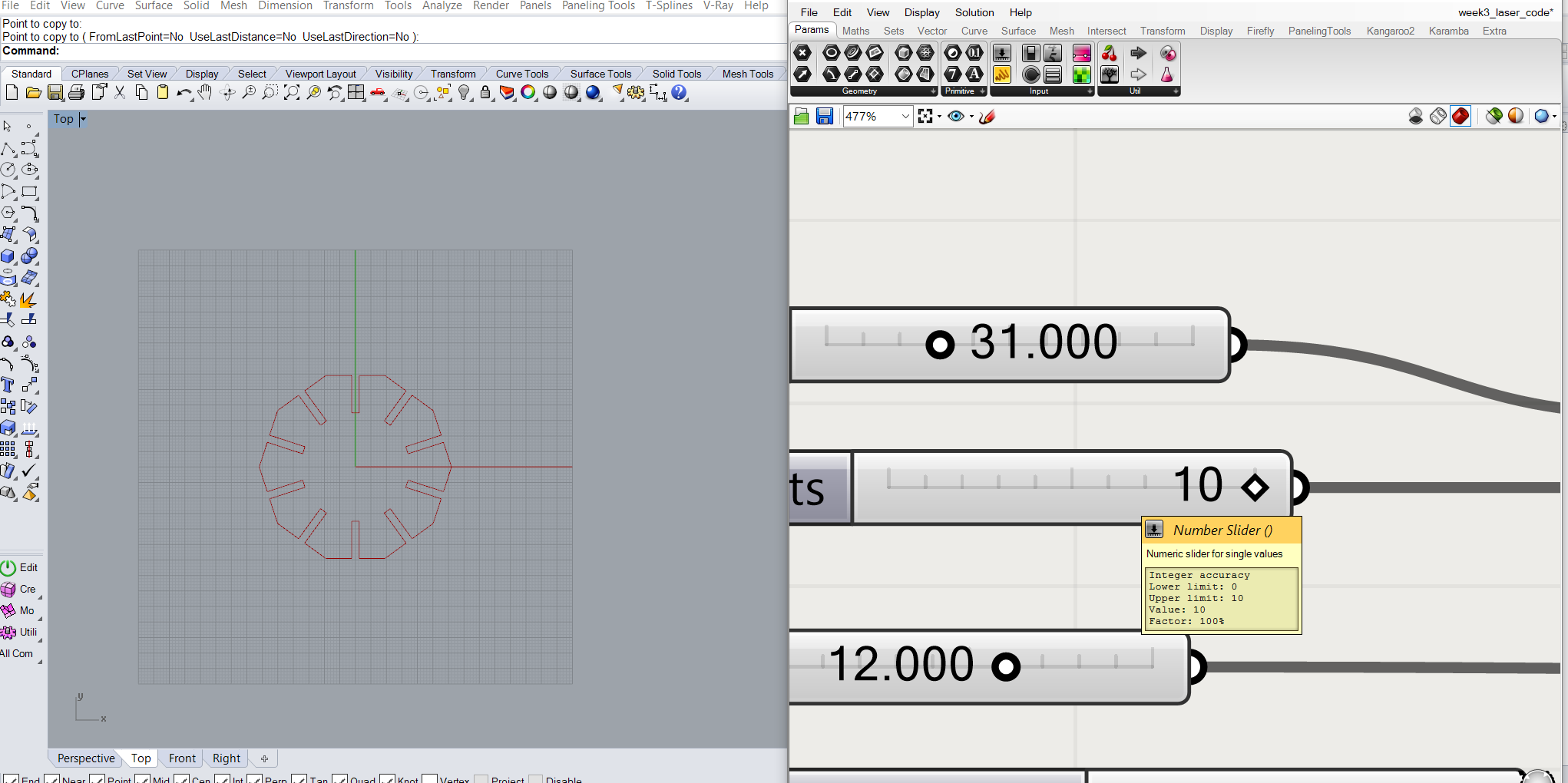
Following animation demonstrates how polygonal geometry along with slots for press-fit construction kit, can be controlled with different parameters.
In total, there are 4 types of module that are going to be laser cut, these are polygons with 4, 5, 7 and 10 sides. Quadrilateral, i.e the square geometry will be cut on 3mm tk transparent acrylic sheet where as pentagon, heptagon and decagon will be laser cut on 2.5mm tk tinted translucent acrylic sheet.
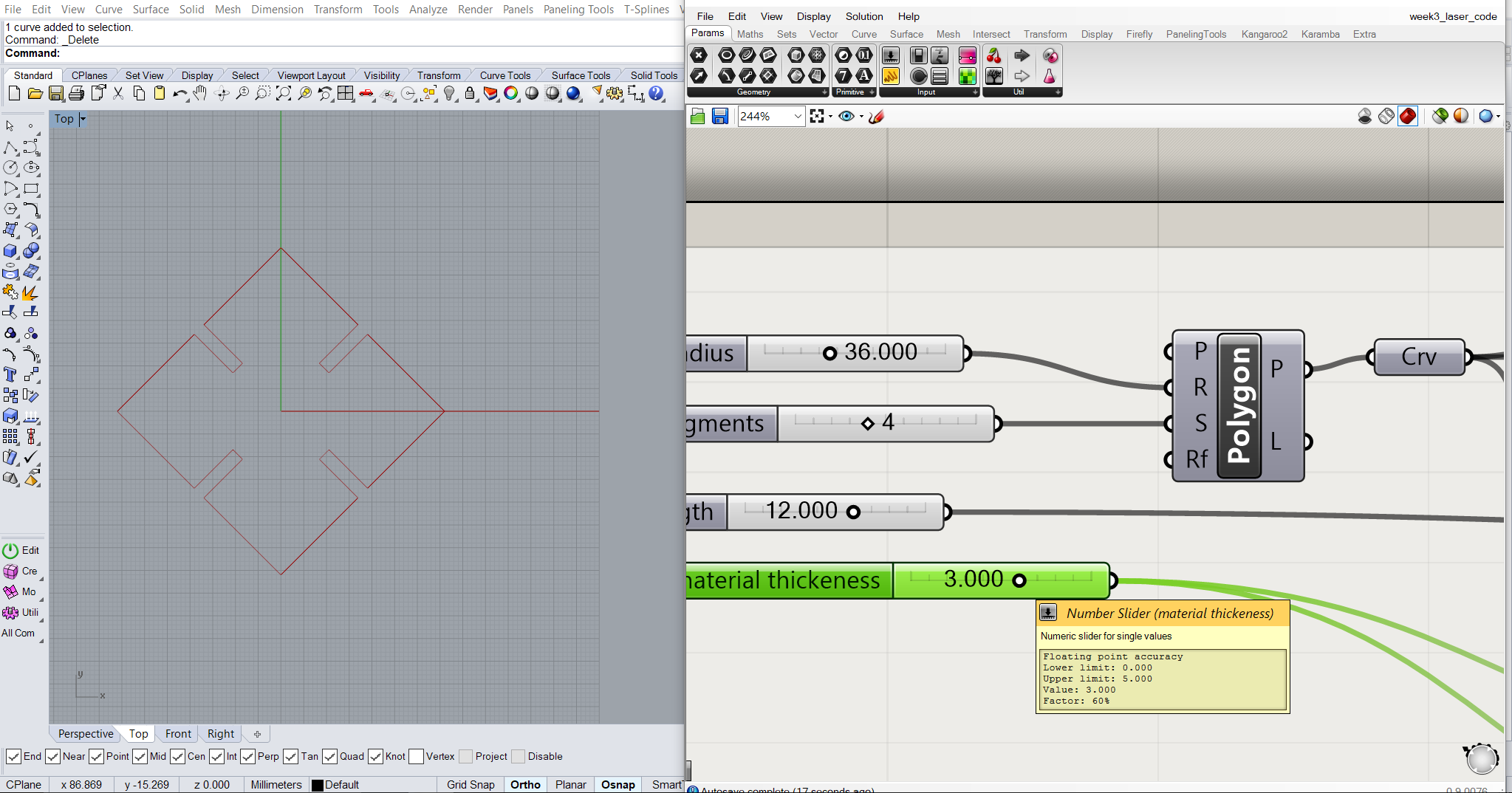
Before baking, I provided following parameters for square modules:
For pengagon module, following parameters were set:
For heptagon module, following parameters were set:
And for decagon module, following parameters were set:
Then I baked them into rhino and save it as .dxf file.
All dimensions are in mm.
Step 5: RDWorks and Cutting
For RDworks and Laser cutting, I followed steps similar to the one I employed for non-parametric design. Then after opening the .dxf file of squares, I provided MinPower and MaxPower of 70% and speed of 20mm/s.
Then I downloaded the file.
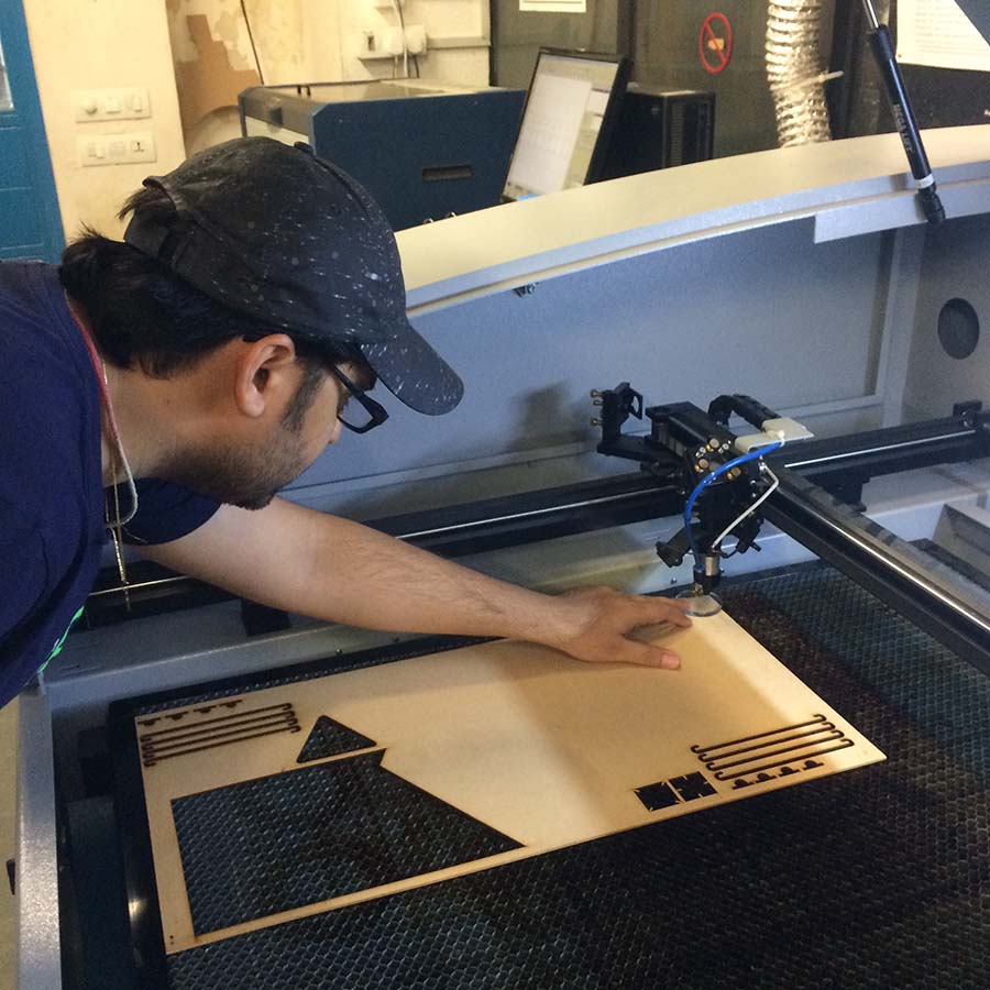
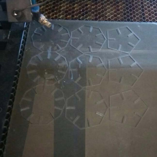
Following image show the work in progress. I removed the top protective layer of the acrylic sheet before initiating the laser cutting.
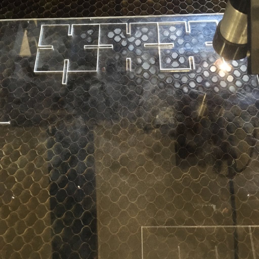
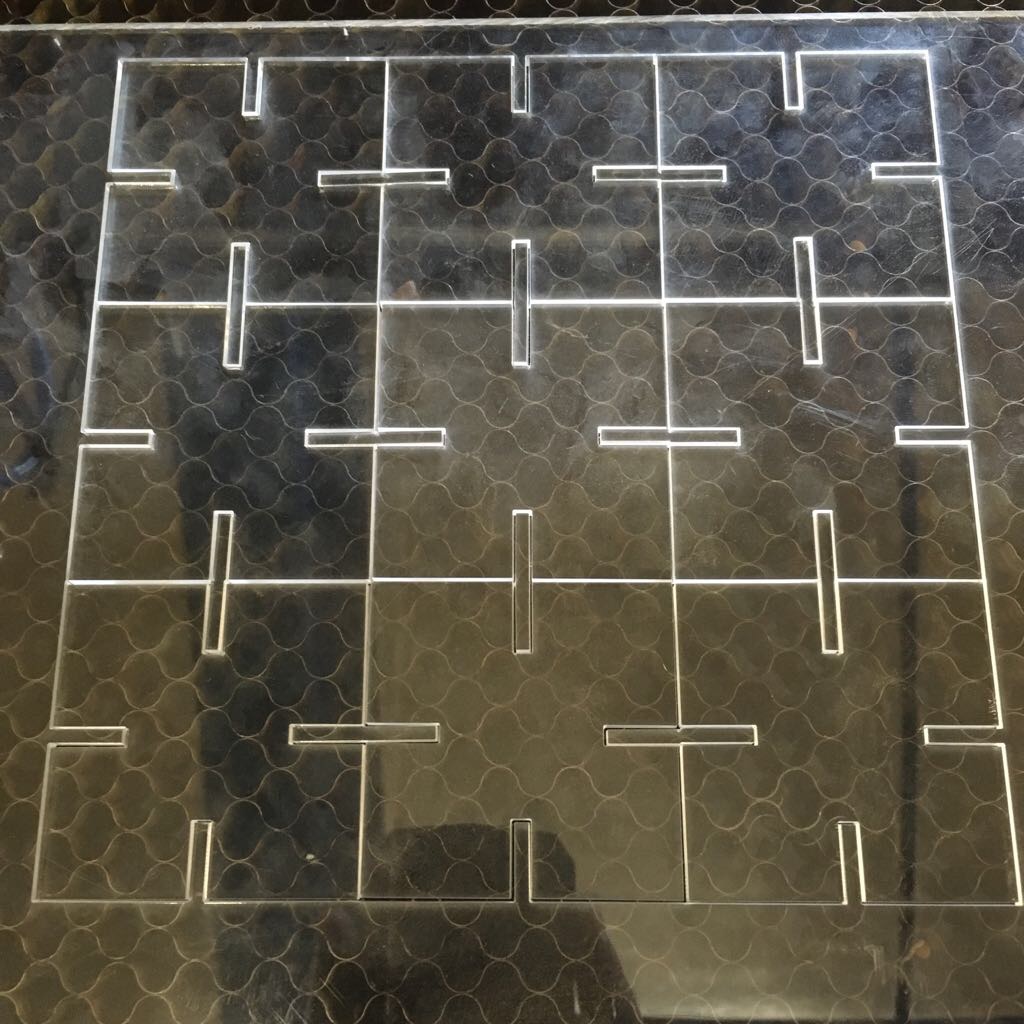
This is how it looks like after laser cutting is finished.
I relogiously followed all the steps for other three polygonal modules too. I am using same MaxPower and MinPower of 70% and speed of 20mm/s for this job as well.
Lastly, I downloaded the file and opened it in DSP control panel screen of the laser cutter and followed all the laser cutting steps to do the final job. -Opening the file, setting the origin, framing the file boundary and then finally hitting the start button for laser cutting head to do the rest of the job.
Following image show the work in progress of the other three modules.
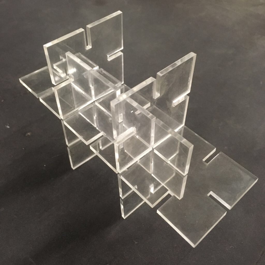
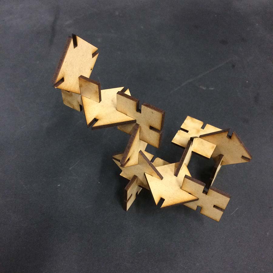
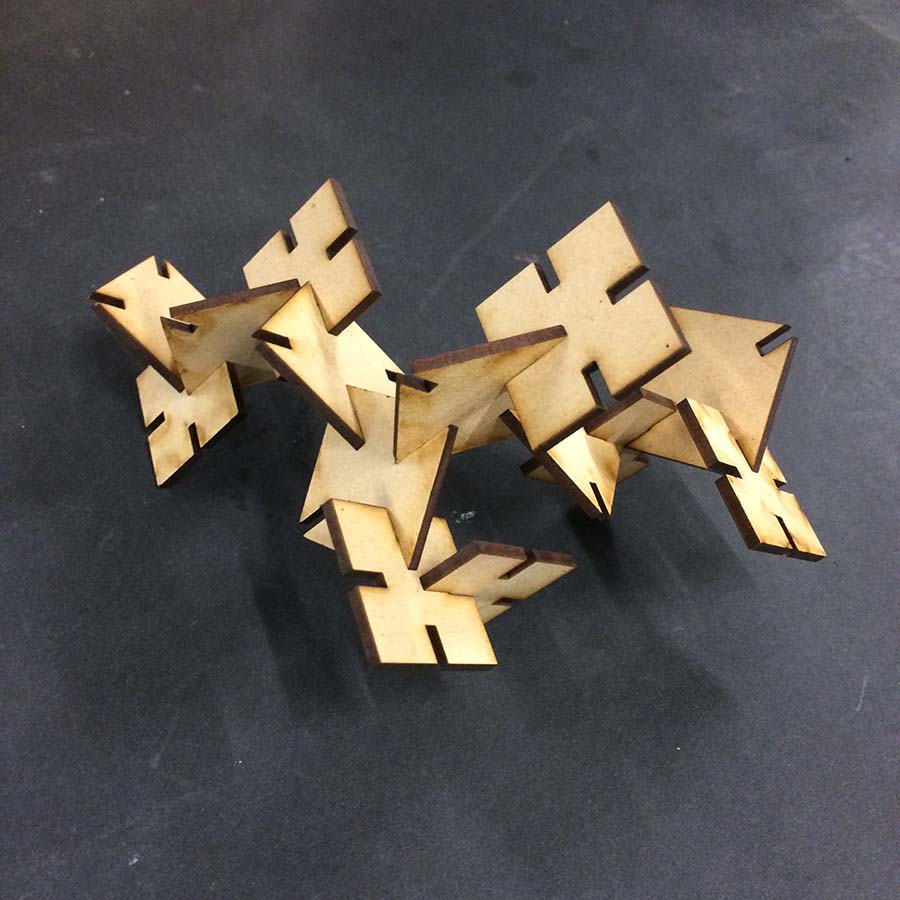
Task 1- Final Object
These are the final sculptural press-fit objects. Made Non-Parametrically. With just two notch variables and similar shapes could be assembled in multple ways
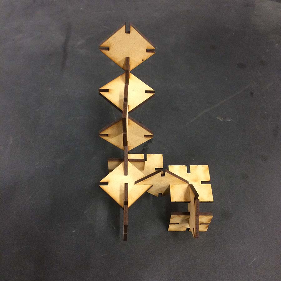
In the video below, I am trying to demonstrate how well laser cut pieces fits to one another.
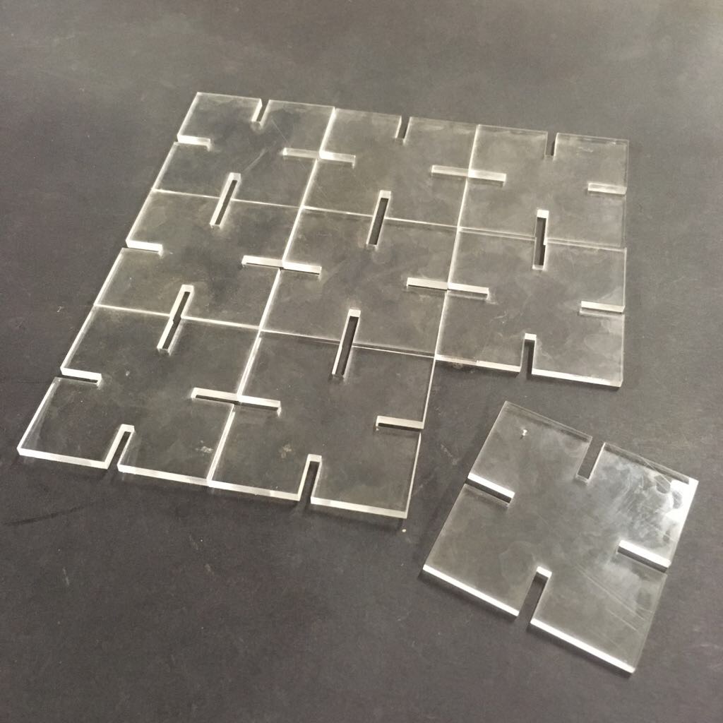
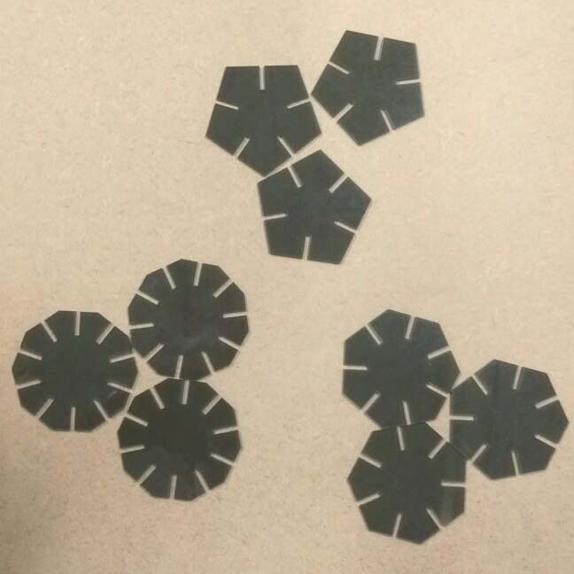
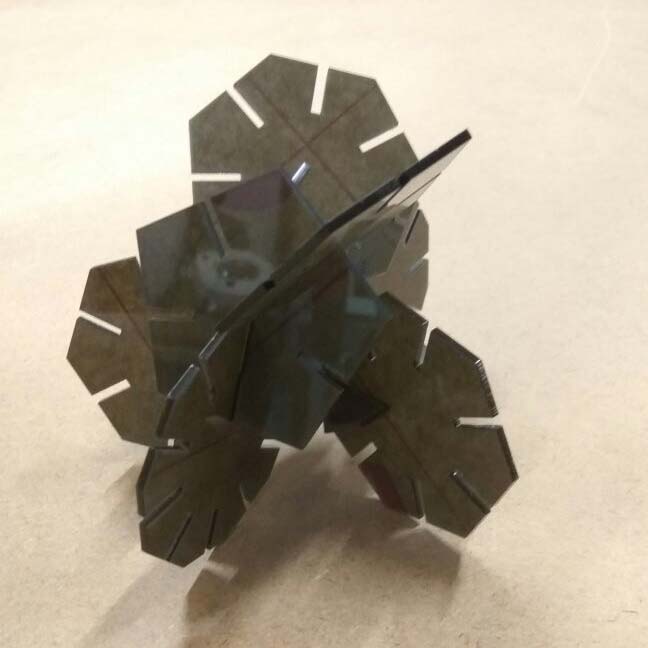
Following are the parametrically designed laser cut modules. First sculpture has only squares and the second is a combination of pentagon, heptagon and decagon.
Task 2- Vinyl Cutting
For this exercise, in our lab, we decided to screen print our T-Shirts using any design/ graphic/ pattern of our own. Screen prinitng process invloved, designing, importing it to cut studio, then cutting it on vinyl sticker and finally printing it on t-shirt. Following steps sequencially demonstrates the process.
Step 1: Design
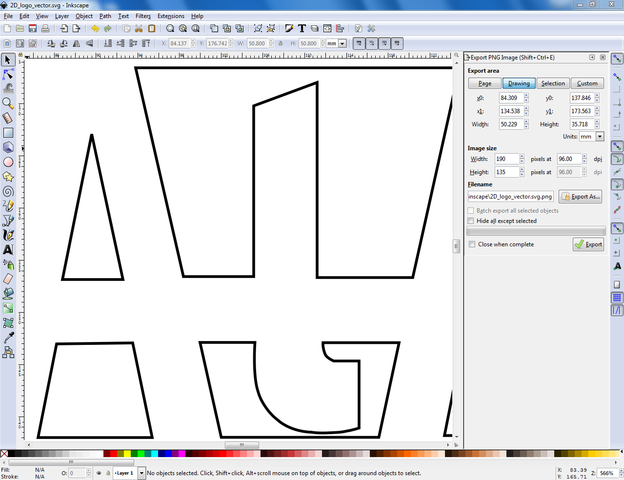
To screen print, I used 2D design of a logo, created in Inkscape in the previous week 2. The task now is to export the file into PDF format to retain vector properties. Then I opened it into photoshop to fill the part of the logo I needed to screen print and also save it to a version compatible to cut studio.
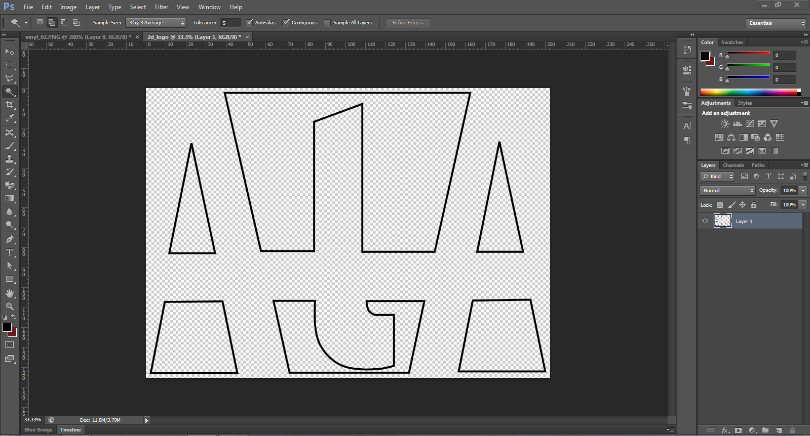

It looked something like this. Now I will open it in the cut studio for futher process.
Step 2: Cut Studio and Cutting
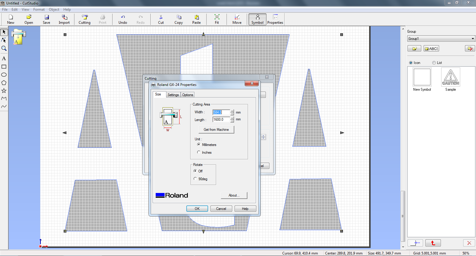
Loading the roll to Roland GX-24 is the first task to get the dimension of the vinyl roll. Once the roll is all set, its is required to press and hold the origin button for 3 seconds to set the origin. Then the force was set to perfect cut the Vinyl cutting.
Following screenshots taken in sequence explains the workflow of creating file for cutting using cut studio.
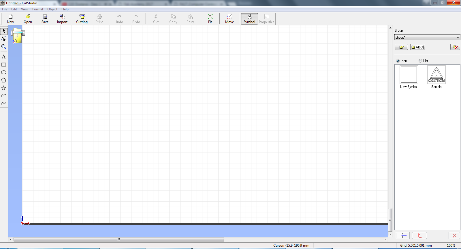
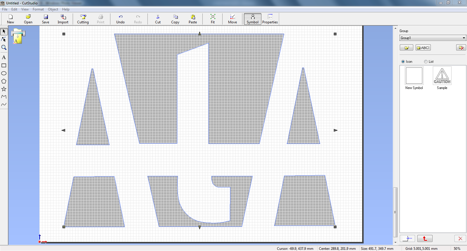
After opening the cut studio software, I opened the logo image and resized it down to fit in the vinyl roll width. Also, to ensure the size of the logo is big enough to be impactful.
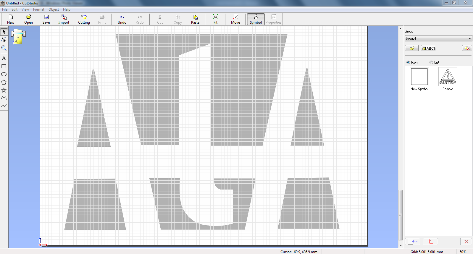
Then the next task was to create image outline.
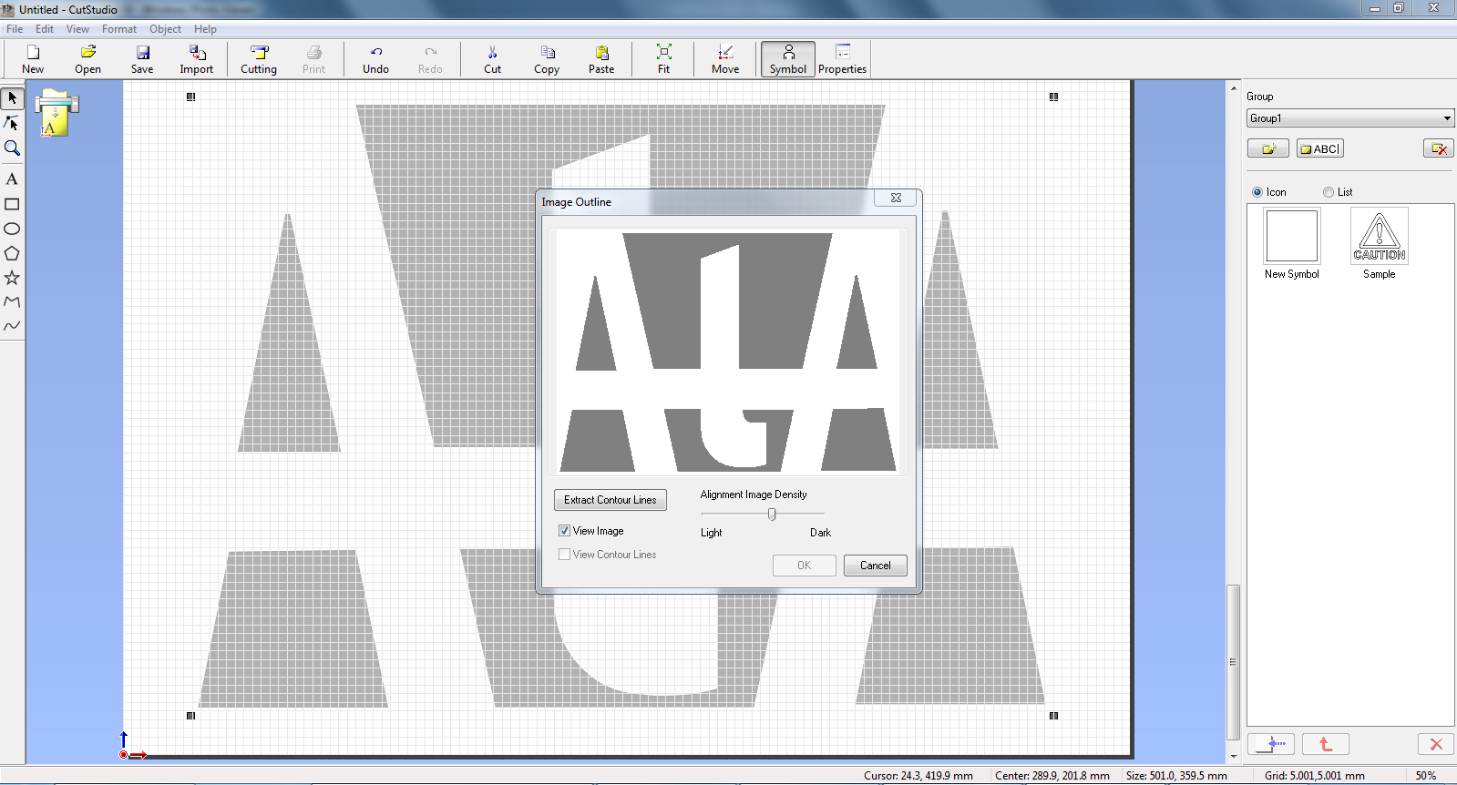
And then extract contoure lines to eventually cut the vinyl sheet.

Then upon hitting the cutting tab, I could see the box appearing asking for the printer, which in our case is Roland GX-24.
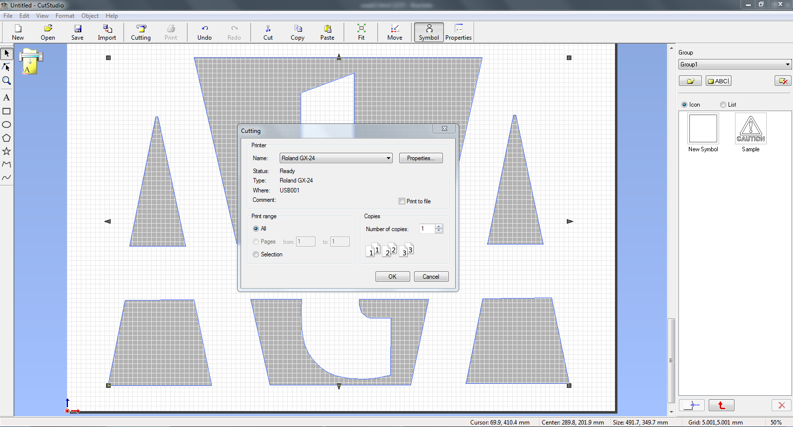
Now final task here is to hit okay so that cutting could be carried out.
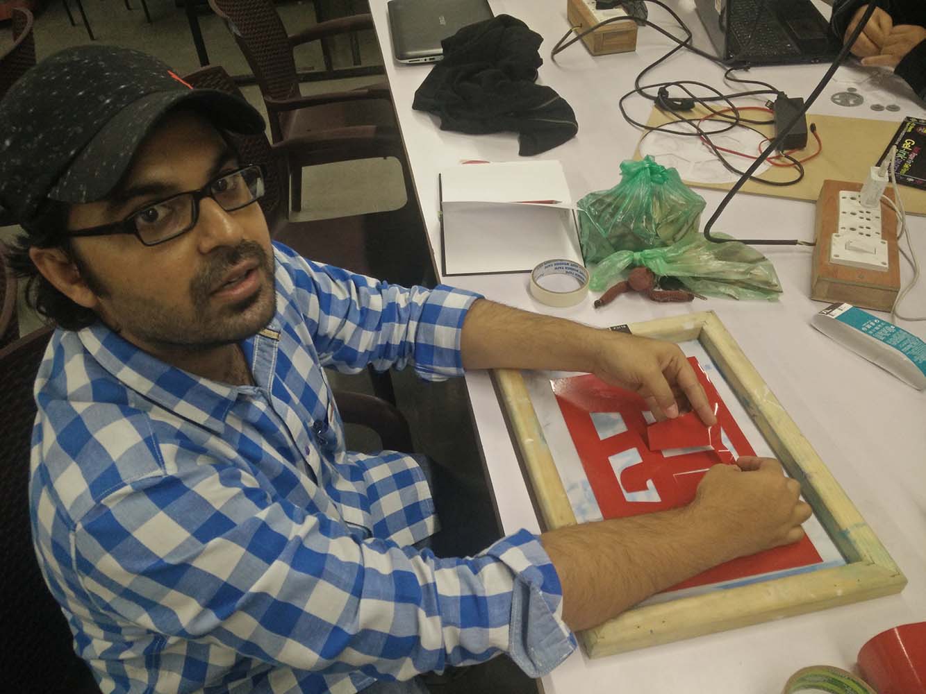
Step 3: Screen Printing
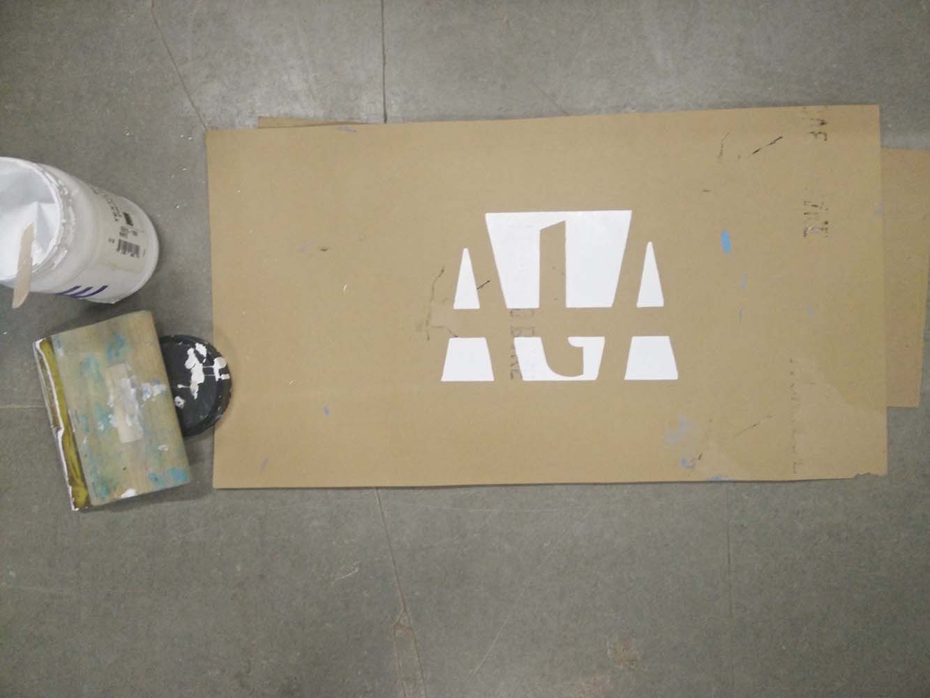
After cutting the vinyl sticker sheet, I mounted it on the screen and removed the part I wanted to print on my t-shirt. This work as a stencil.
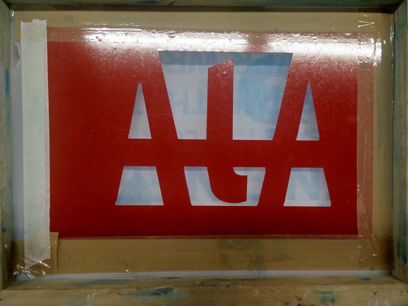
Now before printing on the t-shirt, I choose to test print it on a sheet of MDF and check the porosity of the screen and leakage if any.
To avoid any leak, I covered gaps with a tape.
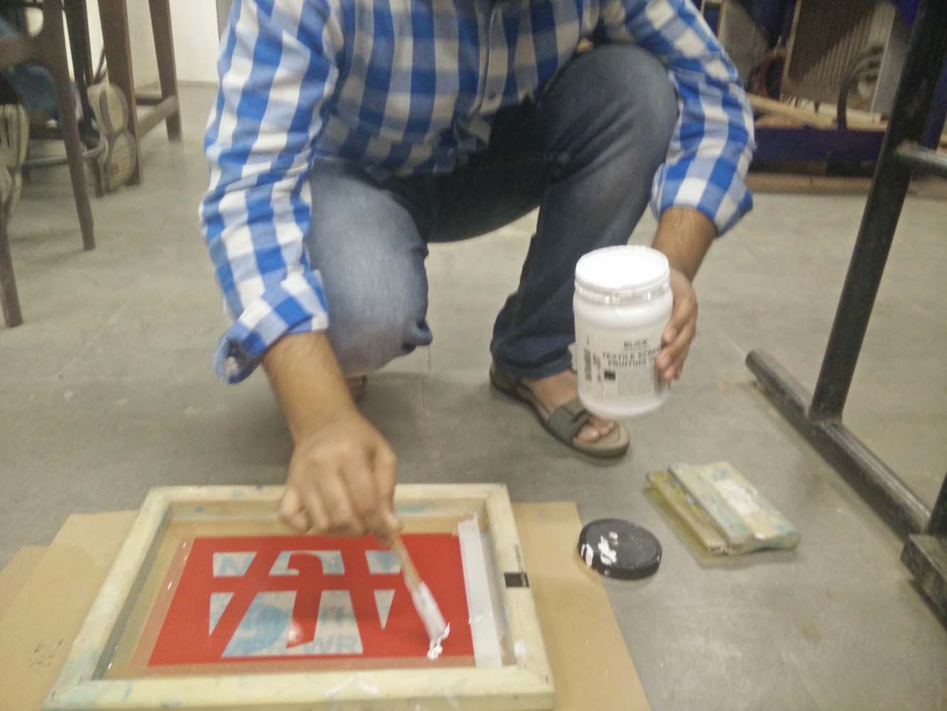
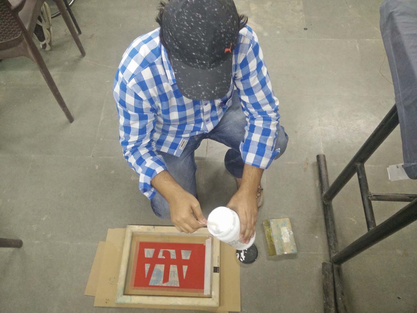
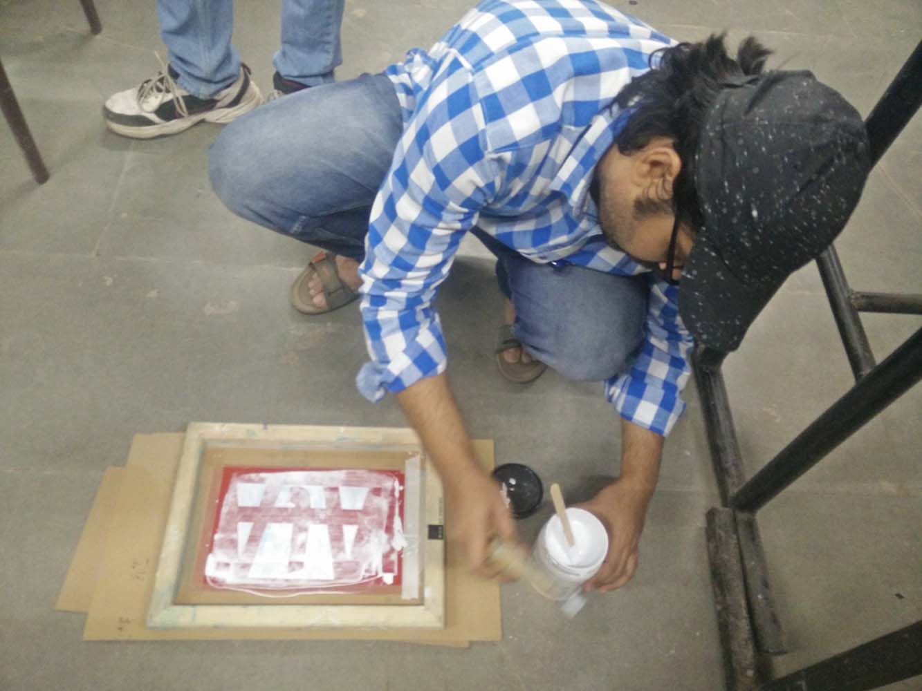
Fabric color was pressed well against the surface to get consistent and even application of it.
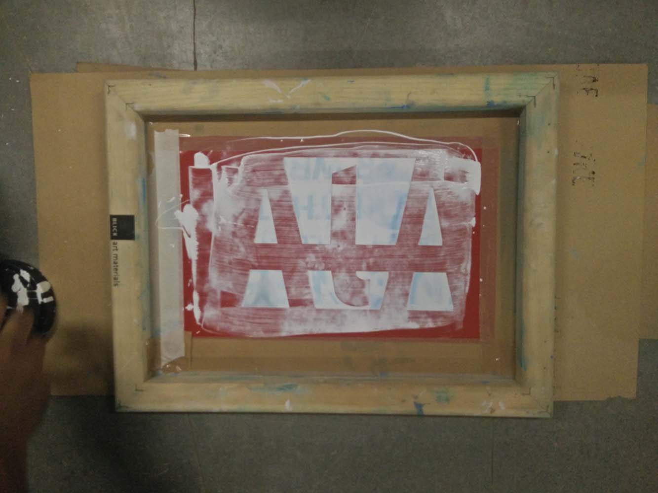
Now after allowing it to dry for a moment, I removed the screen carefully and the print came out quiet well.
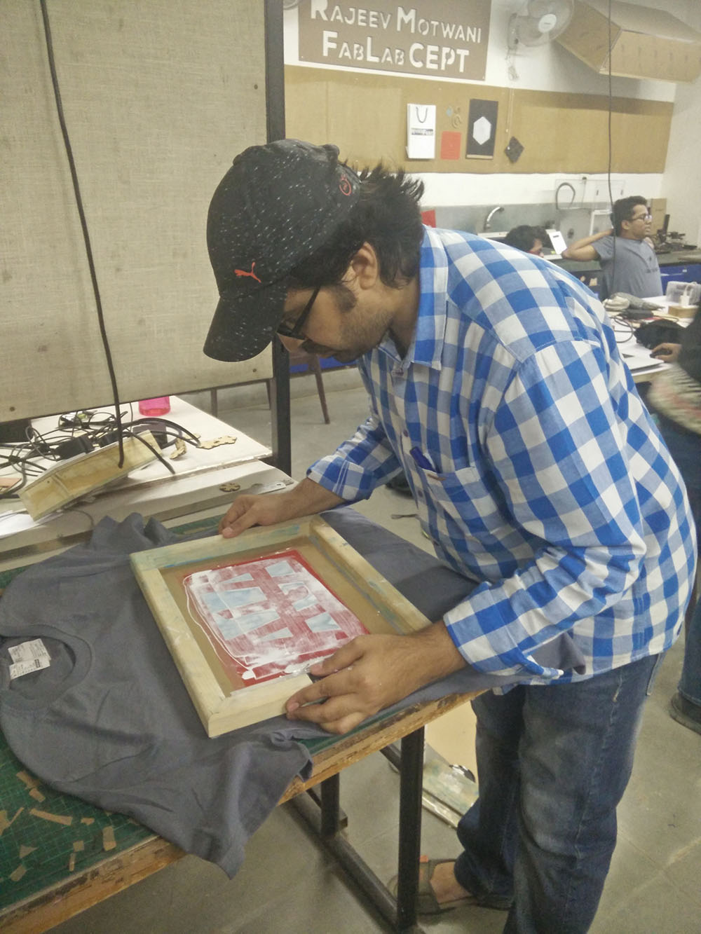
After successful test print, I applied the same process of application onto my t-shirt.
The result is quiet satisfactory.
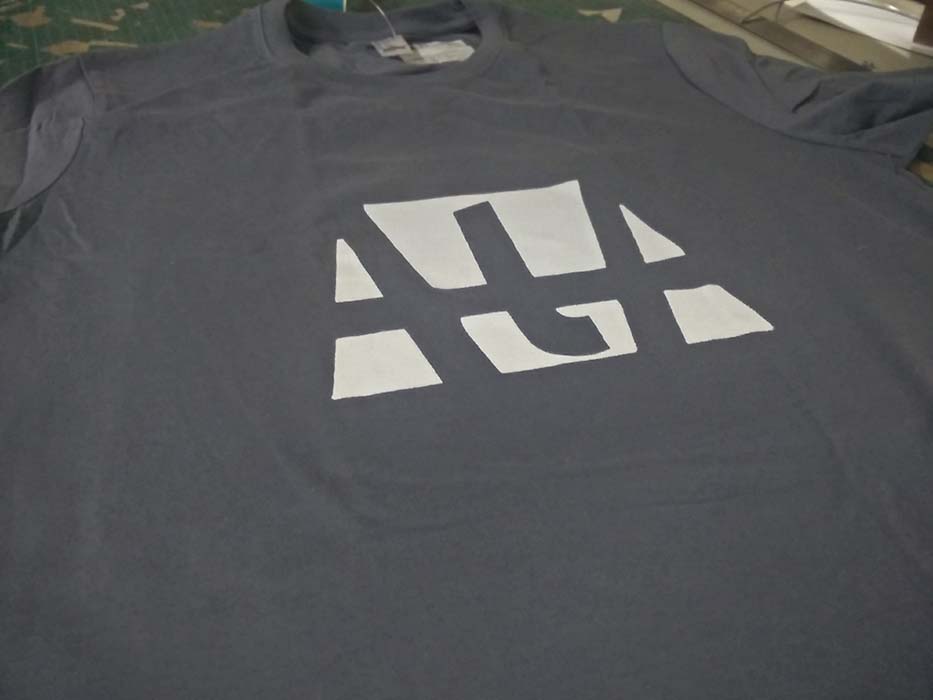
Task 2- Hero-Shot
Links
Week 3 FilesRhino3d
Grasshopper3d
RDWorks