Introduction and Background
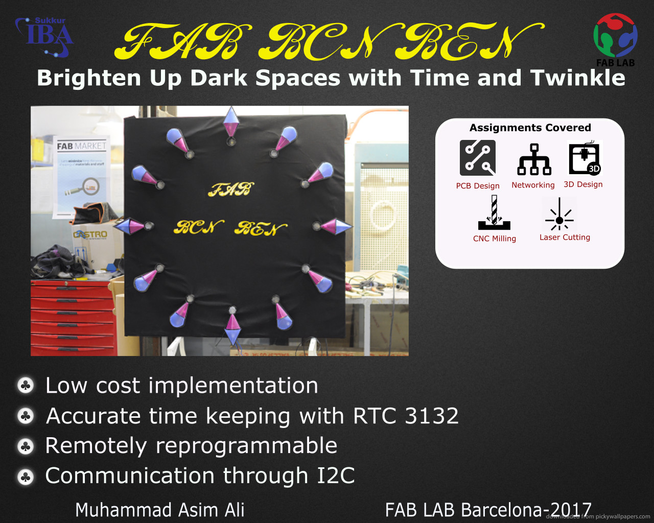
For my final project I want to make a large dial clock suitable for outdoor situation. This looks like an exciting idea as this clock may fill up the empty spaces on the walls of public place could provide entertaining illumination in addition to time .
Ideally, I would like all the elements to be wireless and connected to each other through Bluetooth interface. The master unit causes the slave units to lightup. The time resolution of this clock could be upto 5 seconds. Each dial could have three different colour LEDS (for hours,minutes and seconds) respectively.
For illustrative purpopse I made a simple animation using swish. The animation has been propped up a bit to create some context for viewers.
I have not seen anything like this but the closest thing is the neo pixel rings available at adafruit
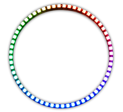
Although they are bright and colorful but no more than a few inches in diameter and certainly not useful for out door installation.
This projects covers the following different modules:
- Designing the dial structure in 3D design softwares.
- 3D Printing or casting dials (whichever is plausible).
- Laser cutting the diffusers as per requirement.
- Design PCB schematic with LED arrays and suitable voltage supplies.
- Interfacing modules together.
Implementation
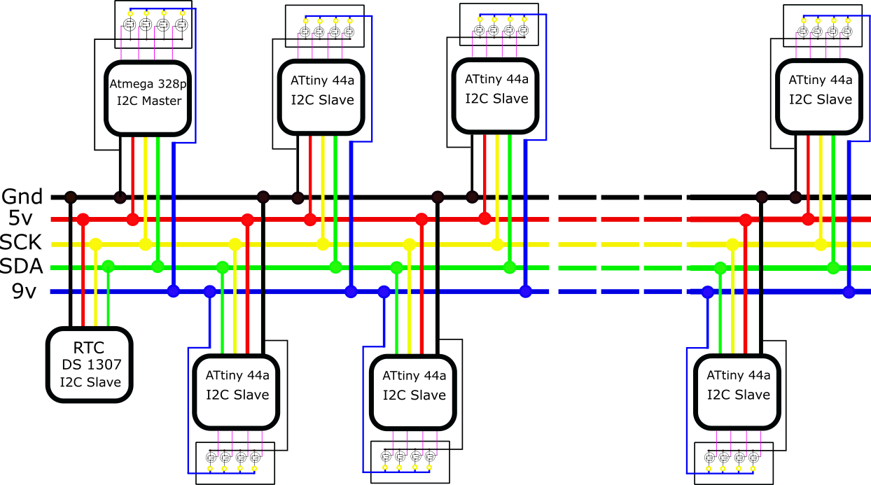
This clock will be hardwired. I intend to use I2C protocol to connect a master device (ATMEL AVR) board with 11 slave devices to operate the LEDs. This protocol provides interconnection of upto 120 devices over simple two wire interface. The data rate of the bus is adjustable and can reach upto 400 kHz which is exceeds our requirements.
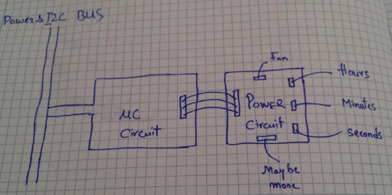
conceptual block diagram of system
Choice for LEDS
The first issue that I had to solve was to find out, how bright is really bright. The LEDS should be visible in day light, work within our power constraints, suitable size and most importantly cost effective. I spent several days read through websites of vendors like mouser , farnell , superbrightLEDs but it was really hard to decide which the optimal part. Finally after alot of deliberation, I decide to buy this model. These are very bright LEDS from CREE which can be placed on PCB. The specifications are as below: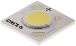
Power Network
After I had decided on the LEDS the next step was to think about the driving circuit which takes the inputs from a micro-controller and drives the LEDS. These LEDs require 9 Volts to operate and could consume about 500 mAmps of current each. So use for simple voltage regulator (which delivers on 1 Amp) of current was not going to be enough. So I starting to look for circuits which can deliver about 2-3 Amps of current at 9 Volts.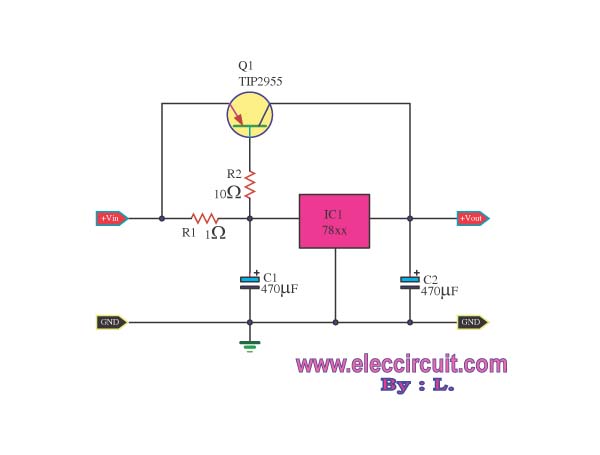
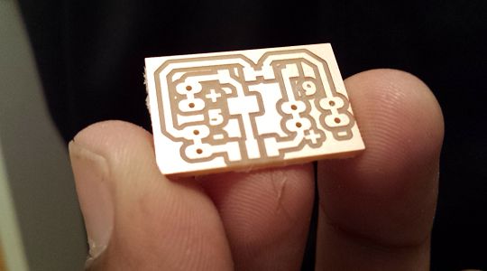
This circuit is cheap and simple enough so I decided to simulate this circuit using proteus to validate the design and see how much of current I can actual obtain using this design.
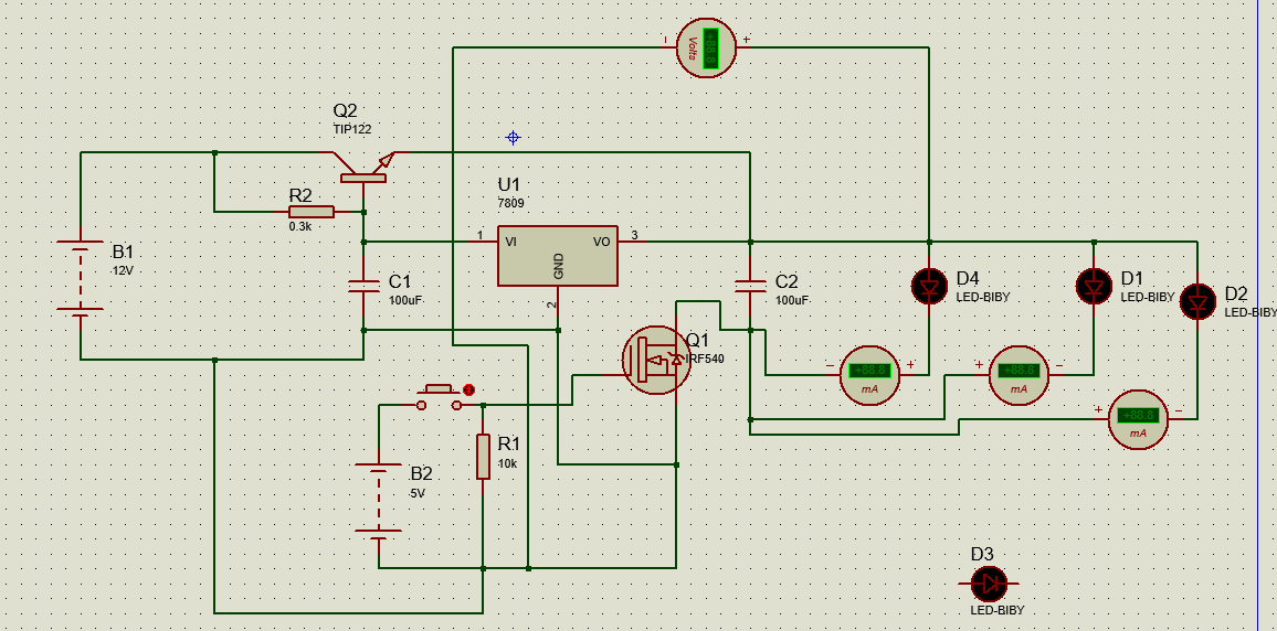
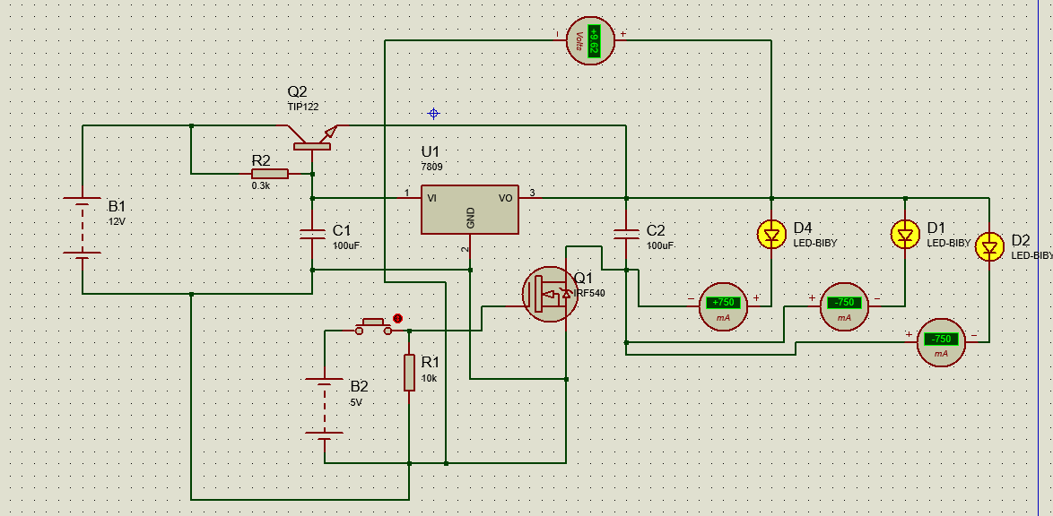
After implementing the board I did tests and realized that the system was not working as expected, I spent several hours trying to figure out possible problems but in vain.
I started looking for answers in the fab inventory and several similar switching applications. I decided to move towards the N-channel Mosfets available in our lab. I would be using N-channel Mosfet (NDS355AN) for the switching application. This Mosfet is available in fablab inventory and I found some references to its usage here .
After doing back ground checks on i2c design, led types and power switching circuits the system diagram was finalized.
Electronics Design
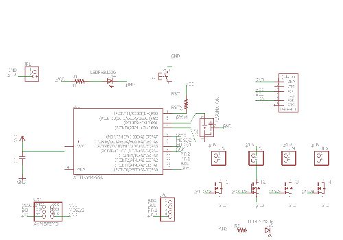
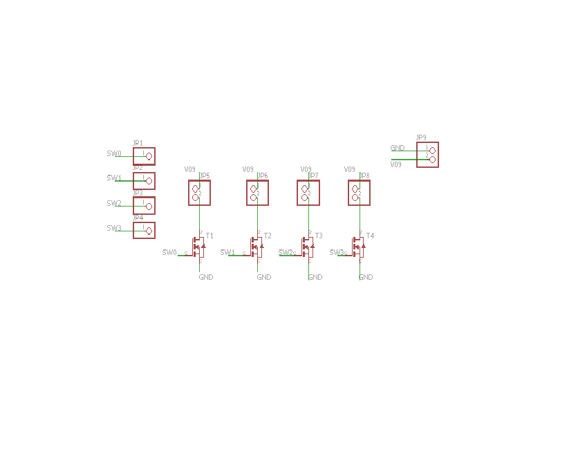
For Assignment 10 I have prototyped a simple Attiny44 based circuit for slave modules to receive instructions from master and turn on the LEDS accordingly. I spent some time modeling the schematic and PCB layout.The circuit includes 4 N-channel NDS355 Mosfets . These MOSFETS can be directly connected to the digital pins of a micro-controller and can support over 1 Amp of currentat @ 30 volts which is ideal for driving high power LEDS.
Next up I started working with the interfacing of micro-controller network through I2C interface. I realized that my orginal all in one design (from assignment 10) requires 0.1 mm drill bit which is expansive and it takes (much) longer to mill the board so I decided to separate the i2c slave and power mosfet modules. This in turn would create a lot of wiring clutter.
The final schematic and PCB layout I2C slave unit and Mosfet boards designed for this project are as follows:
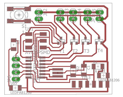
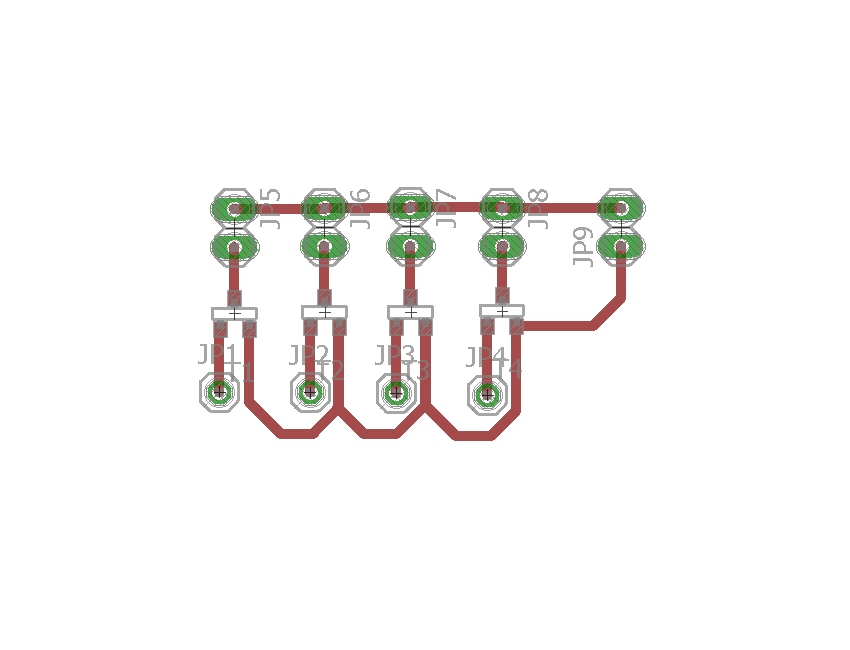
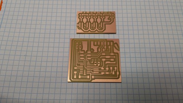
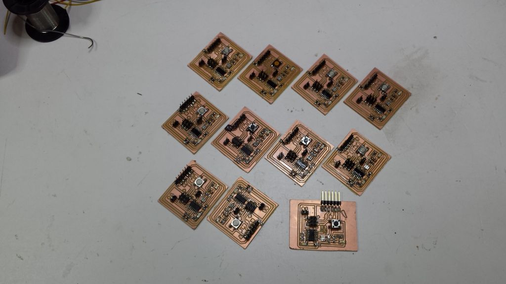
The PCB for micro-controller circuit and LED driving circuits were designed, milled and populated.
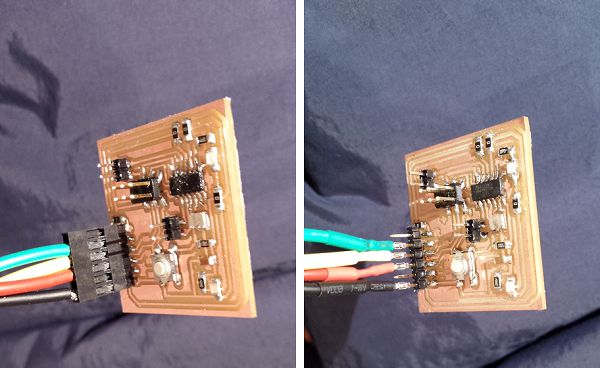
I wrote a simple code to interface my board to arduino over i2c and I was able to PWM my LEDs with controller signal from Arduino (master).
It took alot of effort to populate 11 boards. However this exercise give me a good hands on practice to mill, solder and trouble shoot micro-controller based circuits.
I started working to design a code around real-time clock DS-1307 (or DS-3231). The master will invoke DS1307 (slave) at regular intervals and pass the required instructions to all the recievers simulataneously.
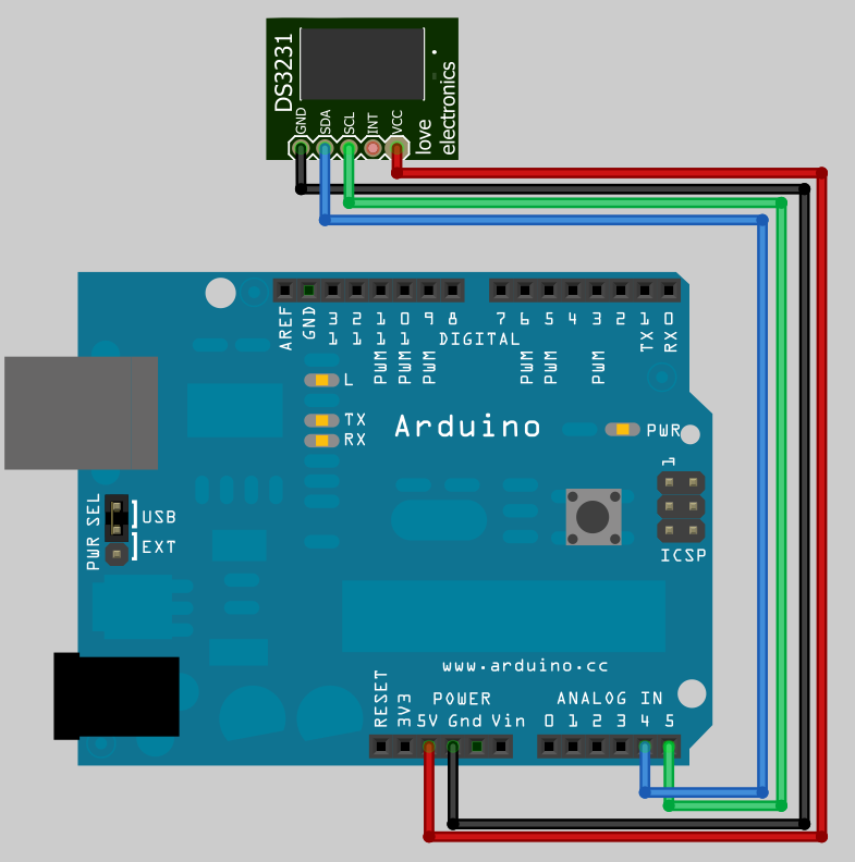
Connection of DS-3231 with Arduino board over i2c protocol
Interfacing DS-3231 with arduino was straight forward. One needs to set the time to the chip to begin with.
Working with DS-3231 I realized that the IC does not always retain current time. So I thought it would be useful if I could update the time at RTC through a handy device such as mobile phone. I implemented a simple mobile app on MIT APP inventor to retrieve current time from RTC and update it simultaneously. Further details can be found on the applications and interfaces assignment page.
Working with electrial network it is important that all the devices share a common ground. In this system the micro-controller circuits require 5 volts dc while high power LEDs require 9 volts. To simplify overall system I designed a voltage regulator circuit. Thus there are two voltage circuits.
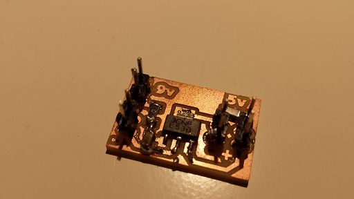
So to simplify electrical circuitary I used a 5v voltage regulator LM2940 which provides maximum current of 1A. I tried to derive all micro-controller boards through this regulator; however this regulator started to get very hot even after afew minutes of usage.
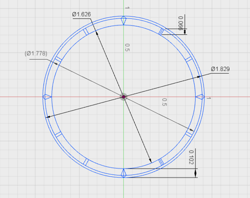
Design of Dials
Next I decided to work on the structure of clock dials. This is a very important aspect of the project. The main problem here stems from the fact that what dimensions will be percieveably good when look at from (lets say 20 meters). This is really hard to decided and I didn't find any good google results to this (infact I don't know how to explore this problem). What I have in mind for design is this.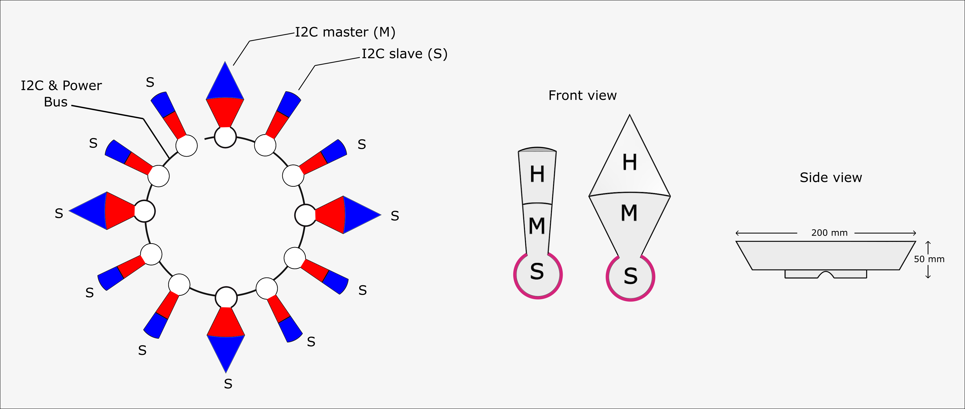
The design of the dials is a bit tricky as the dial has to encase a couple of PCBs, a small fan for exhaust, should be ventilated and yet able to withstand torrential rain. I am still uncomfortable with 3D design, lets see how it goes.
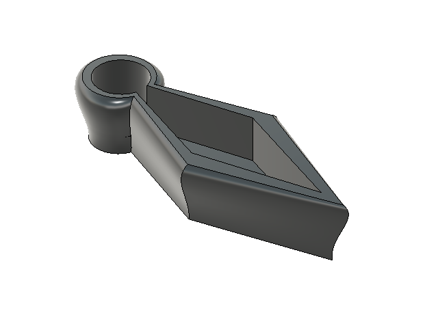
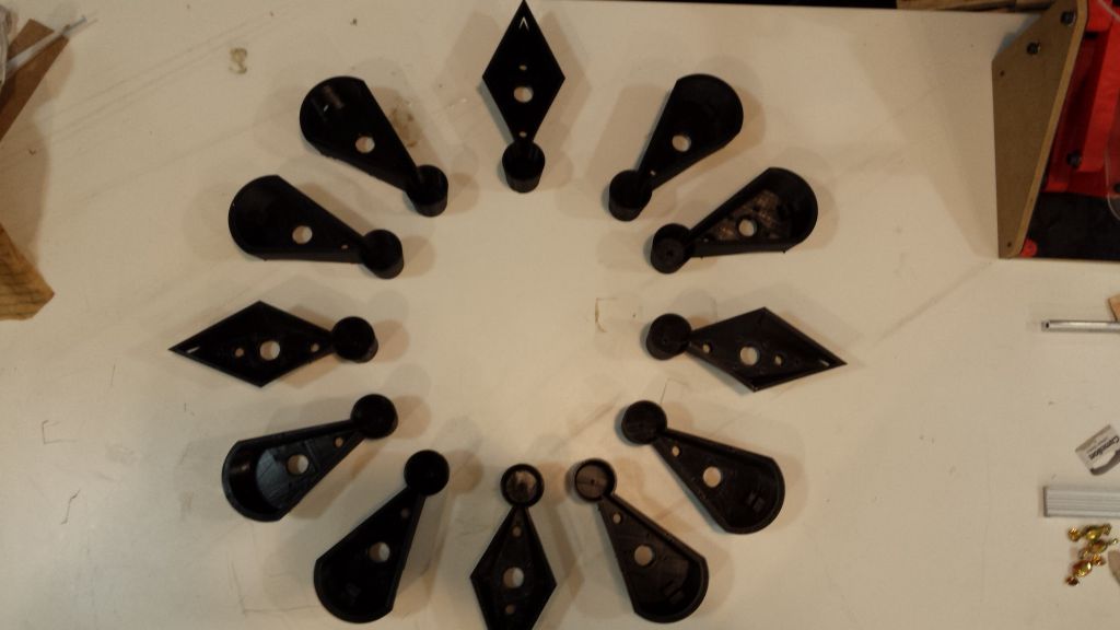
As I finalized the design and started printing these modules I got first hand experience of limitations and tolerances of a 3D printing. I must say that it is very hard to get accurate design. The details below 2 mm are hard to reproduce.
After weeks of printing I was able to print the dials I needed.
The Fusion360 source files can be found here and here.
Design and Laser Cutting of the Diffusers
The purpose of diffusers is to smoothen the effect of highly bright leds and to give a glowing effect. I used propellene type plastic (0.5mm thick sheet) for this purpose.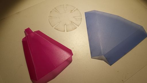
Design of diffuser material for the dials has been a very important learning experience. I had to do several iterations of design and laser cutting to optimize the overall results.
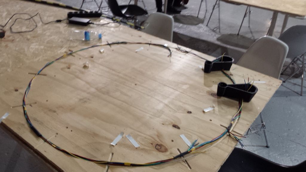
Setting up the plywood platform
In the implementation phase I decided to cut the dial positions on a plywood sheet. Since the dials need to mounted on the wall along with the power and data cables. Keeping in view the dimension of dials and plywood available I decided to fix the diameter of this clock to 1.2 meter.Power and Data Harness
This is one of the most important segment of the project which has caused me major headaches. The choice of cable and type of connector has been a source of concern for me as it might effect the performance of the I2C network. I had been thinking about the network layout of the project. The clock would span about 1.5 meters in diameter and I was concerned weather a network bearing 12 I2C devices will be able to ensure reliable communication at high data rates. For a quick test I hooked up 10 meters of UTP Cat.5 cable between 2 Arduino Mega boards and was able to obtain reliable communication. The experiment was successful however I realized that fragile and brittle nature of CAT.5 cables makes it more unsuitable to use it as communication bus, therefore I would use better gauge wire for this purpose.I choose stranded alumunium wires with silicon insulation. The diameter of these cables is 0.5 mm.

From my personal experience I have come to feel that the dupont connectors (which are connectors of choice) in micro-controller based project are not snug. Most of the connectors were loose and coming off easily therefore I decided to secure the wires with heat-shrink.
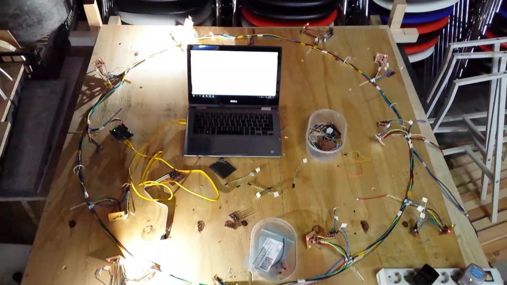
Once all the components were ready it was time to place everything on the wooden dial and test how everything fits together
some more tests to check the code Mosfet circuits and LEDs.
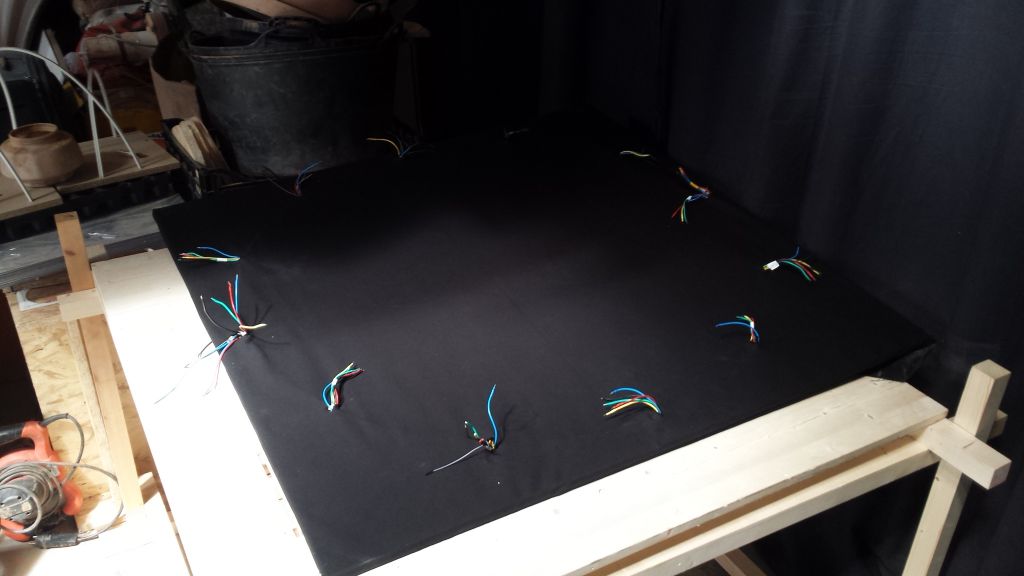
I thought a wooden dial with multi-coloured cable would not be esthetically appealing so I decided to wrap this board with a black sheet of cloth. There may have been other (better) solutions but this is all I could think off in those moments when I had to push for completion of the project.
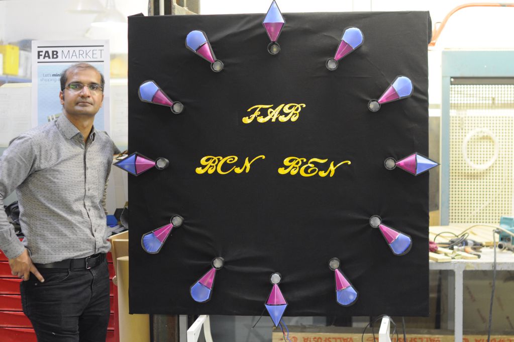
Finally putting all the components together, I finally had my clock ready.
Concluding Remarks & Reflections
I am very happy to be able to complete this project and that it works (almost). This has been a massive opportunity for me to experiment and learn from my mistakes. I have acquired working know-how of several design and manfucturing techinques and I have developed understanding to decide which design techinques, processes and materials would be suitable for a given application.I have also come to recognize the business plan and cost considerations one must contemplate while designing products which are supposed to be reliable and commercializeable.
Although the final design of this project is far from where it should be; but importantly now I have all the requisite skills and understanding to take this project forward.
Downloads
Bill of material here.Find 3D design files here.
Find CNC design files here.
Find Diffuser design files here.
Find PCB design files here.
Find Arduino files here.

This work is licensed under a Creative Commons Attribution-ShareAlike 4.0 International License Copyright © 2017 Muhammad Asim Ali
This work is licensed under a Creative Commons Attribution-ShareAlike 4.0 International License Copyright © 2017 Muhammad Asim Ali