Muhammad Asim Samejo
Output Devices
The week is all about creating digital output:
- add an output device to a microcontroller board you've designed and program it to do something.
For this I decided to make on of the most important components for my final project. Since for my final project I would like to control bright LED lights from a micro-controller. As these LEDS operate at 9V and draw more than 100 mAmps each they can not be connected directly to 5v circuit
.
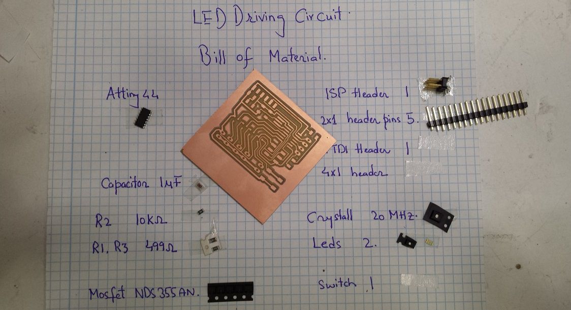
Therefore, I had to design a circuit for this purpose. For my requirements, I considered numerous components including relays, BJTs, Darlington pair transistors, H bridges and after alot of deliberation I decided to use N-channel NDS355 Mosfets . These Mosfets have many advantages such as small form factor, they require no biasing circuitary and can be directly connected to a micro-controller pin. These mosfet can draw upto 1.7 Amps of current at 30V which is over and above my requirements.
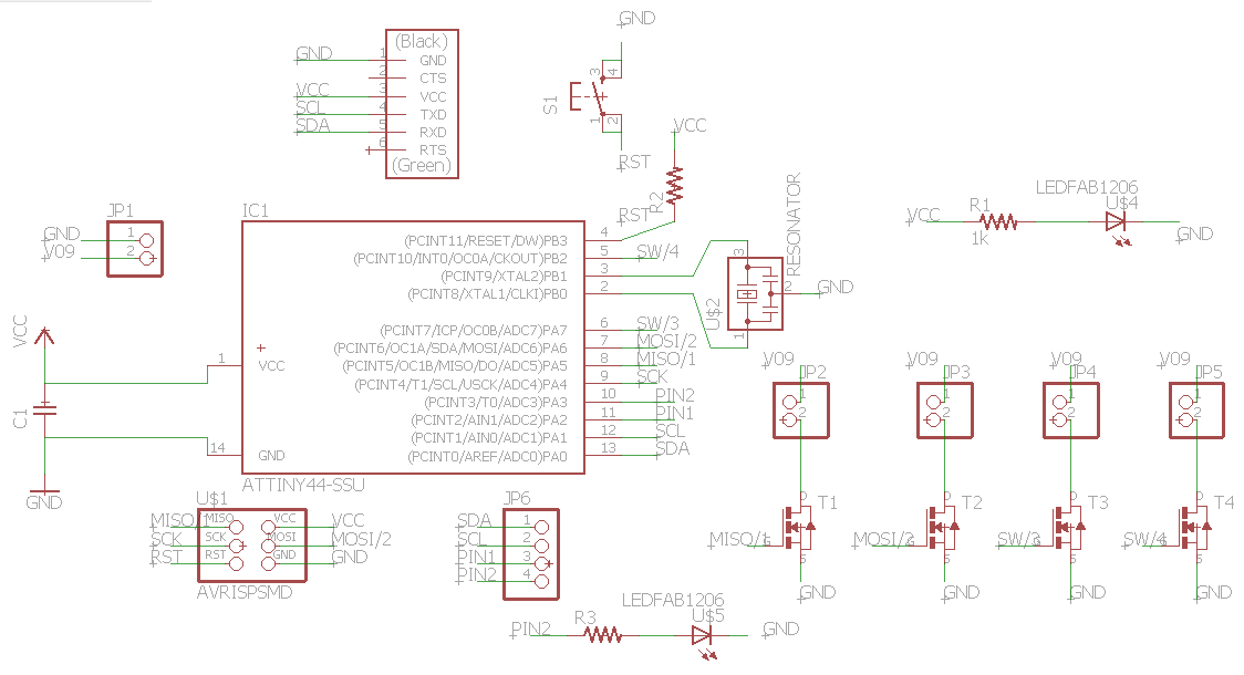
Electrical Schematic of the system.
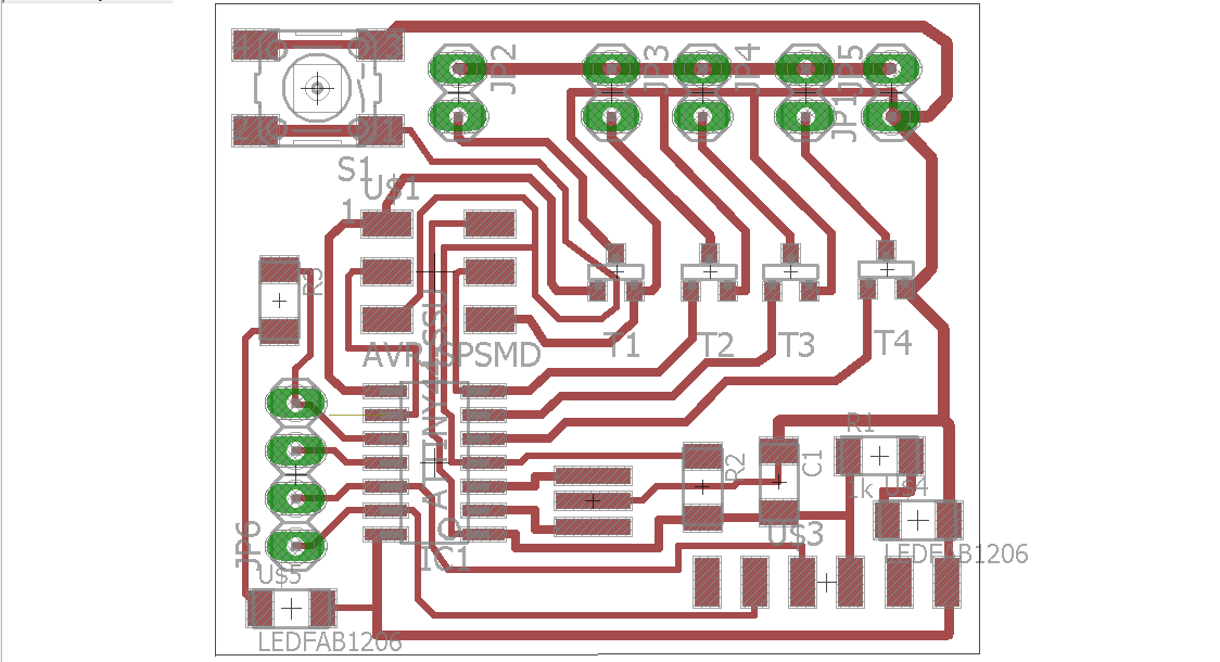
PCB layout of the system.
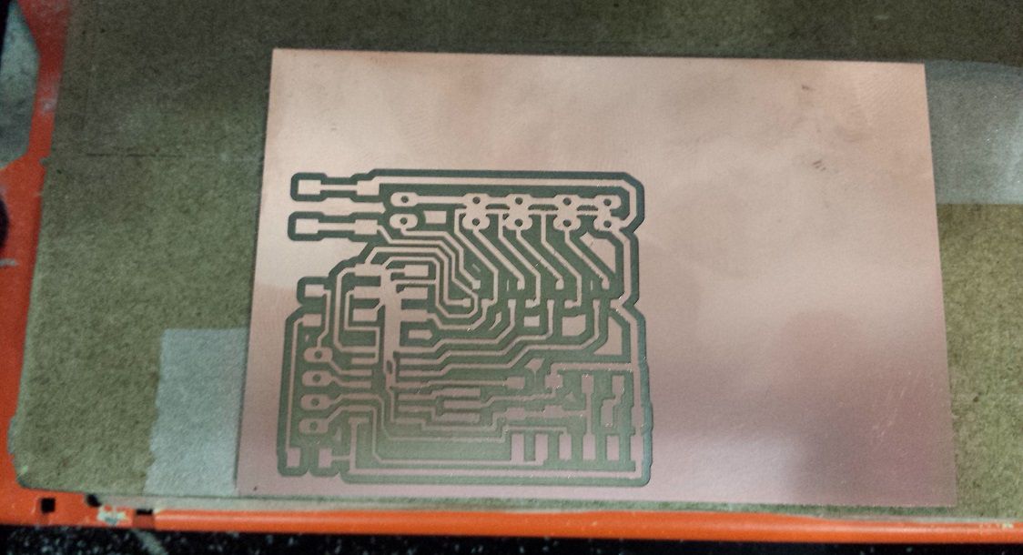
Milling with 1/64 drill bit didnt work.
Results of milling after 0.01" drill bit.
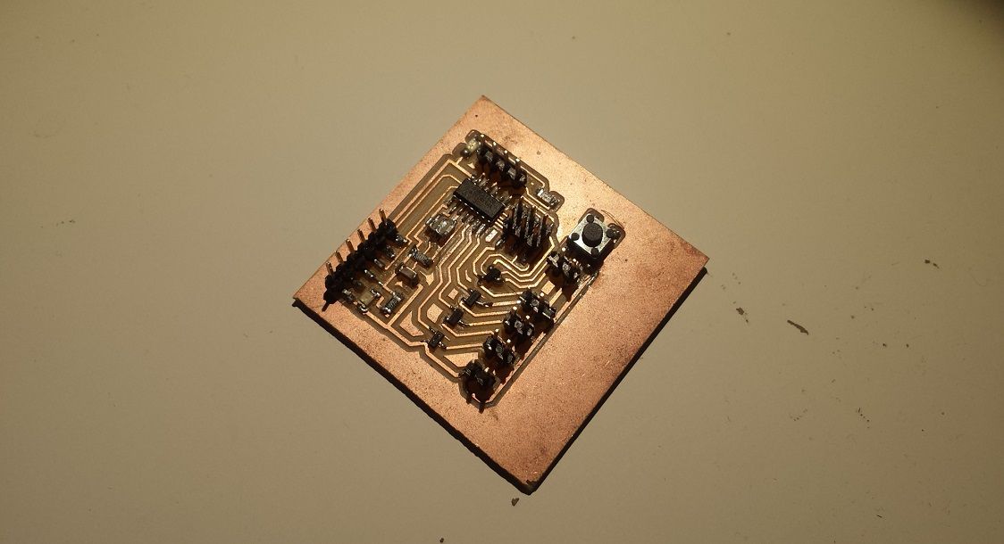
The completed board
Once the population of the baord was complete I tested all the traces using DMM to ensure connectivity as required. I connected the module with my FAB ISP and sucessfully burned the bootloader following steps outlined in Assignment 8.
Bootloader burn sucessful
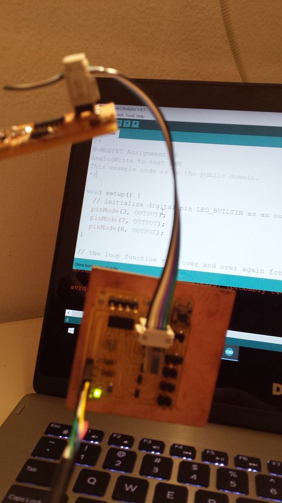
Next to test the operation of the mosfet (as required) I programmed the device with a blink LED code
/*

Week 10 (Output Assignment)

with AnalogWrite to test PWM

This example code is in the public domain.

*/


void setup() {

  // initialize digital pin LED_BUILTIN as an output.

  pinMode(3, OUTPUT);

  pinMode(7, OUTPUT);

  pinMode(8, OUTPUT);

}


// the loop function runs over and over again forever

void loop() {

 digitalWrite(3, HIGH);

 analogWrite(7, 64);

 analogWrite(8, 64);


 delay(400);

 digitalWrite(3, LOW);

 analogWrite(7, 128);

 analogWrite(8, 128);

 delay(400);

 analogWrite(7, 192);

 analogWrite(8, 192);

 delay(400);

 analogWrite(7, 255);

 analogWrite(8, 255);

 delay(50);

}
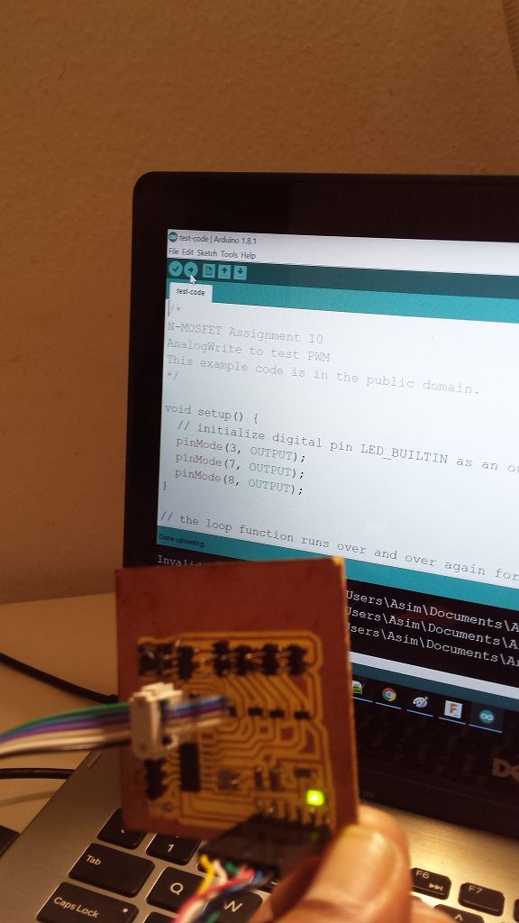
Program upload sucessful
The high power LEDs were connected with a power supply while micro-controler board powered using FTDI cable.
Although all the components are placed on a single layer but this design requires milling with a 0.01" drill bit. Also due to constraints the traces of ground network are very thin. I think as LED circuit would draw in excess of a few hundred m Amps this circuit may not be a practical design.
Learning Outcomes
- N-Channel Mosfets I used in this assignment have been a valuable find for me. The simplicity of use and impressive current and voltage rating of these mosfets makes them suitable for a variety of applications.
- Another valueable lesson to take away from this assignment was to keep ground common between 5v circuit powering the micro-controller circuit and the 9v circuit feeding the high power LEDs.
- Due to their small form factor soldering of mosfets is a particularly difficult task. From my experience I found that by placing a bit of solder on the drain pad and soldering the drain pin; we can solder the transistor swiftly.
Downloads
find all source files here.

This work is licensed under a Creative Commons Attribution-ShareAlike 4.0 International License
Copyright © 2017 Muhammad Asim Ali
This work is licensed under a Creative Commons Attribution-ShareAlike 4.0 International License
Copyright © 2017 Muhammad Asim Ali