Mechanical Design
This week is all about to design and making a machine in a group. It was quite interesting to work in group after doing 8 weeks assignments individually. I enjoyed the whole learning and execution process of this week with my group members Tomas, Muhammad Asim, Sohail, Nisar and me Fida.
Assignments of this week
- As an individual
- As a group
- Explained your individual contribution to this project our your own web page
- Team planning and execution of project
- Describing the problems and proposed solutions
- Listing the future development oppertunities for this project
- Including your design files hero shot photos of the machine and short video of its functionality
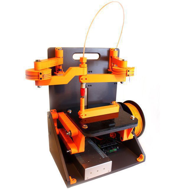
Initially we started with discussion in group manner to decide what machine we should design and make that operational so after huge group discussion we as team decided to make a Wally 3D Printer(special type of 3D printer) Details about this 3D printer
.
After deciding the machine we started to develop the work flow for the execution and divided them into individual parts for each individual group member.
So we finally came up with the division and distribution of individual tasks assigned to each group member. the list of divided tasks is given below.
- Developing the wooden frame using Rhino CAM (Its me - Fida)
- XY-axis assembly mechanics (Muhammad asim & Nisar)
- Z-axis assembly mechanics Sohail
- HotEnd and Extruder Tomas
So as for as my part of contribution in this project was concerened I developed the wooden case or house for the printer's assembly.
General details about the Technical specification of the Frame
- Built off a rigid back board. The board can have ribs attached to make it more rigid. The material is TBD based on prototype needs
- Wally could be designed to fold fairly flat for storage or portability. Think suitcase with a handle on the side. Legs could fold out to make it free standing, or it could be attached to a wall
- The design can be scaled. Perhaps a 12" backboard width at the small end. That might give more than a 6" cube build volume. A 15" backboard width might give something on the order of 10" Diameter, or an 8" square, or a 10" x 7" Rectangle -- all with a 10" height. I think this would be a good design center
- All axis are driven from stepper motors through a Spectra fishing line drive on preferably smooth pulleys.
- The two X,Y arms are driven by rotating the elbows. This gives a build area that is limited by an arc from the shoulder with a straight elbow to the hot end.
- The ratio of the stepper drive to large elbow pulley determines the resolution and torque. 0.025mm or better with a reasonable ratio with a 16-32x microstep.
- The Z axis is a 4 bar linkage that keeps the bed flat as it is rotated up and down through an arc. Gravity lowers and a stepper winding a string raises it.
- The build platform moves through an arc as the Z is changed. The X,Y Arms have to compensate for the displacement in the Y axis (perpendicular to the back board).
- A convenient place for a spool is on the lower back. Filament would be fed up through a Bowden extruder and over the top and down to the hot end.
I downlaoded the rhino design file for this house already available on internet. you can download that file here
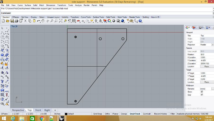
After that I opened that file in rhino and brought some minute changes not in the shape but in the measurments.
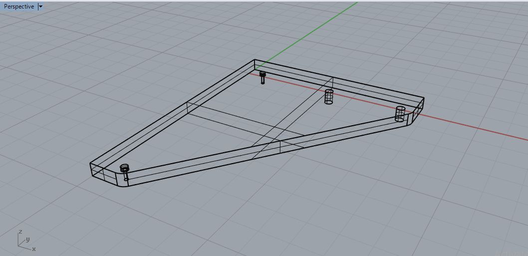
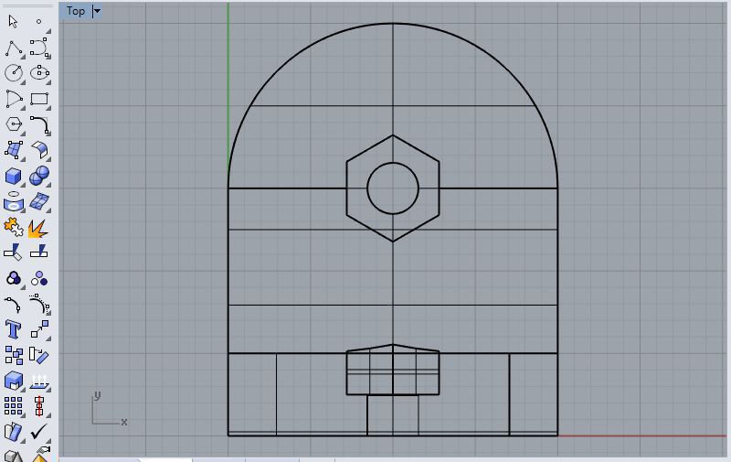
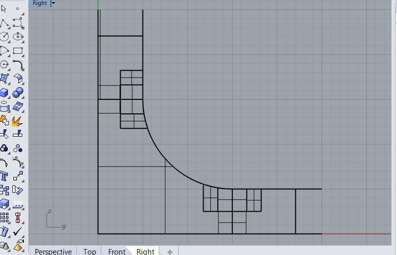
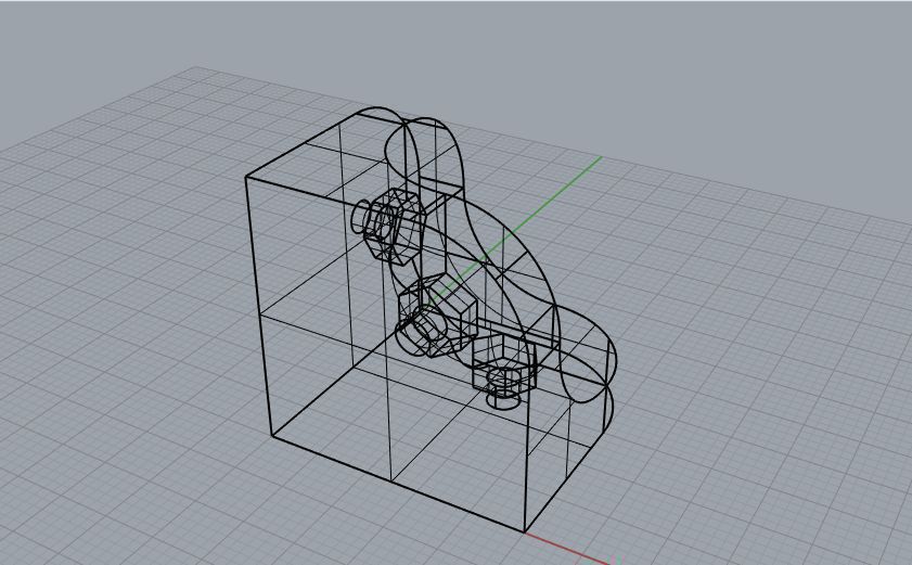
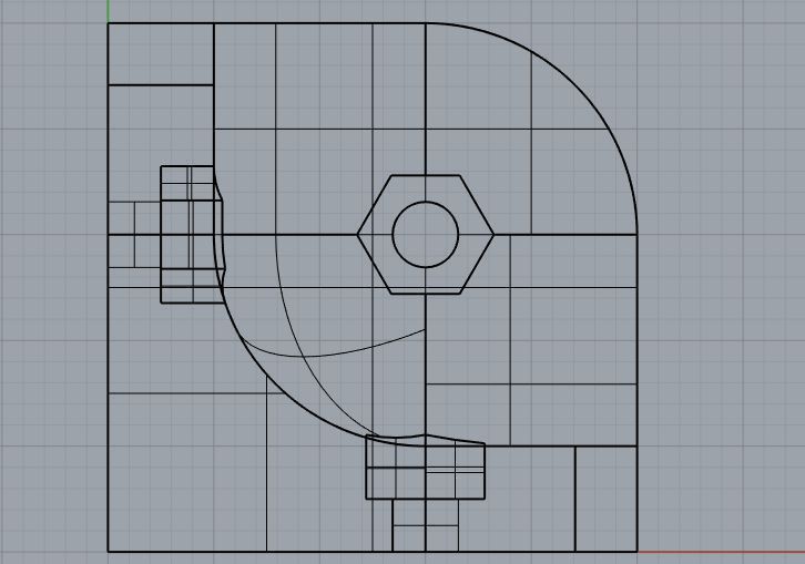
Here are some snapshots of the design
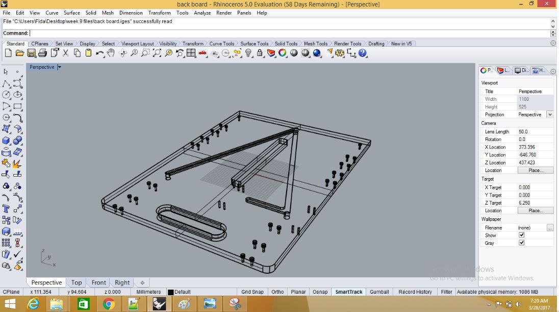
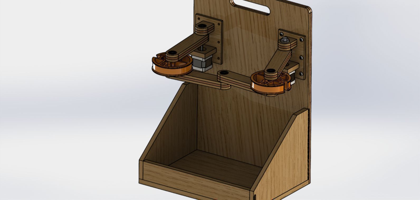
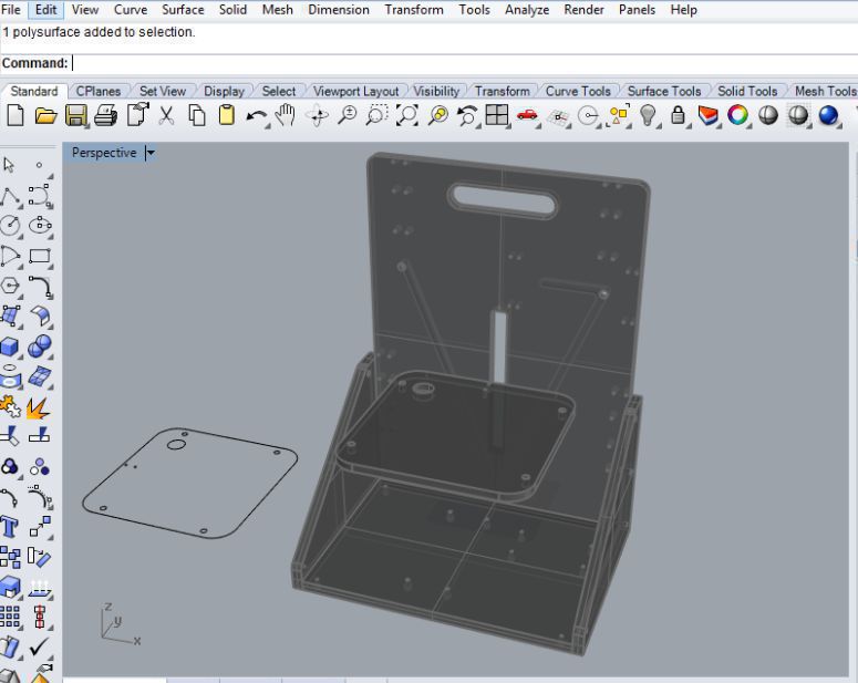
Assembling all the parts of the design to get the final wooden case rhino design of the house for the printer is shown in the picture below.
After that I did the process of generating the GCODE using Rhino CAM and got ready the file for the milling
I repeated same process for generating the GCODE as I did in week 7 at Valldaura while making something Big My week 7
Final wooden casing for the printer is ready now
Addition to this I was also suppose to 3D print the joints for joining the base of the wooden case with sides and Back of the house for that I also used Rhino for designing the joints and printed them using Prusa I3 printer.
In order to join the case strong enough I needed four corner joints among four, two front joints are symmetrical and two back joint are symmetrical to each other so I decided to 3D print one of the front joint twice and one of back joint twice which were symmetrical. Some snapshots of design are shared below.
front joints
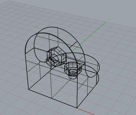
back joints
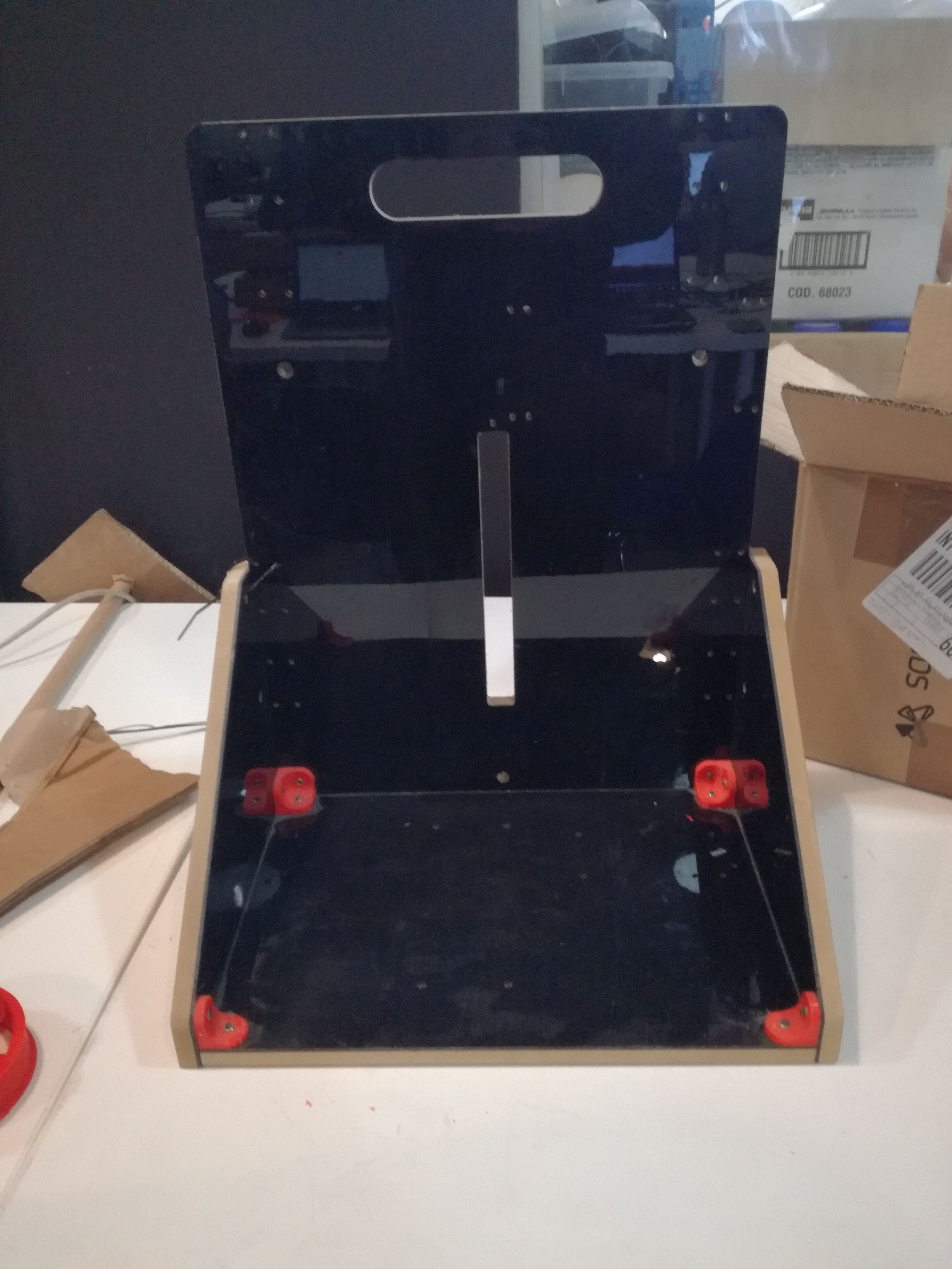
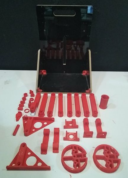
Here is the picture for 3D printed items and wooden case
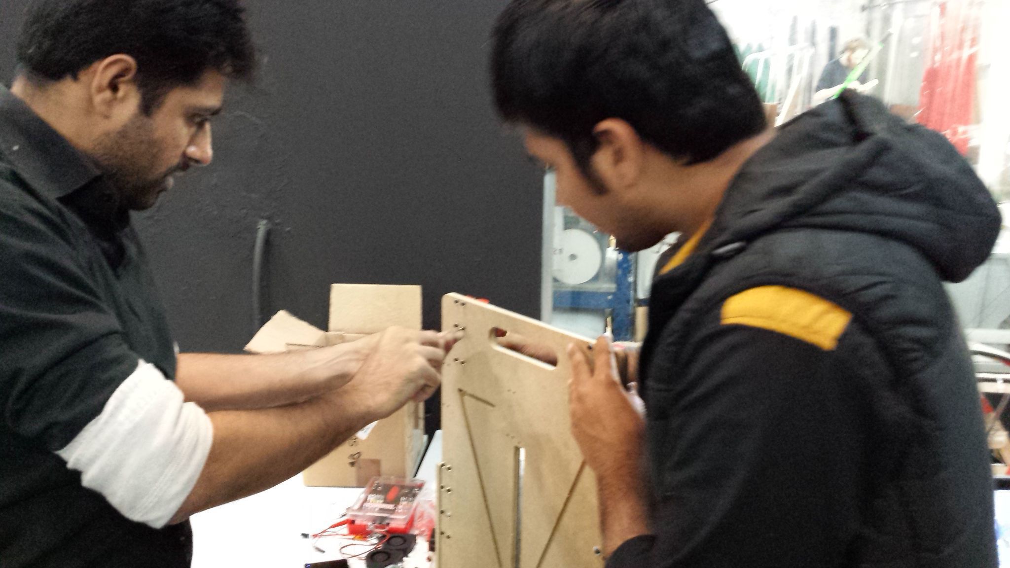
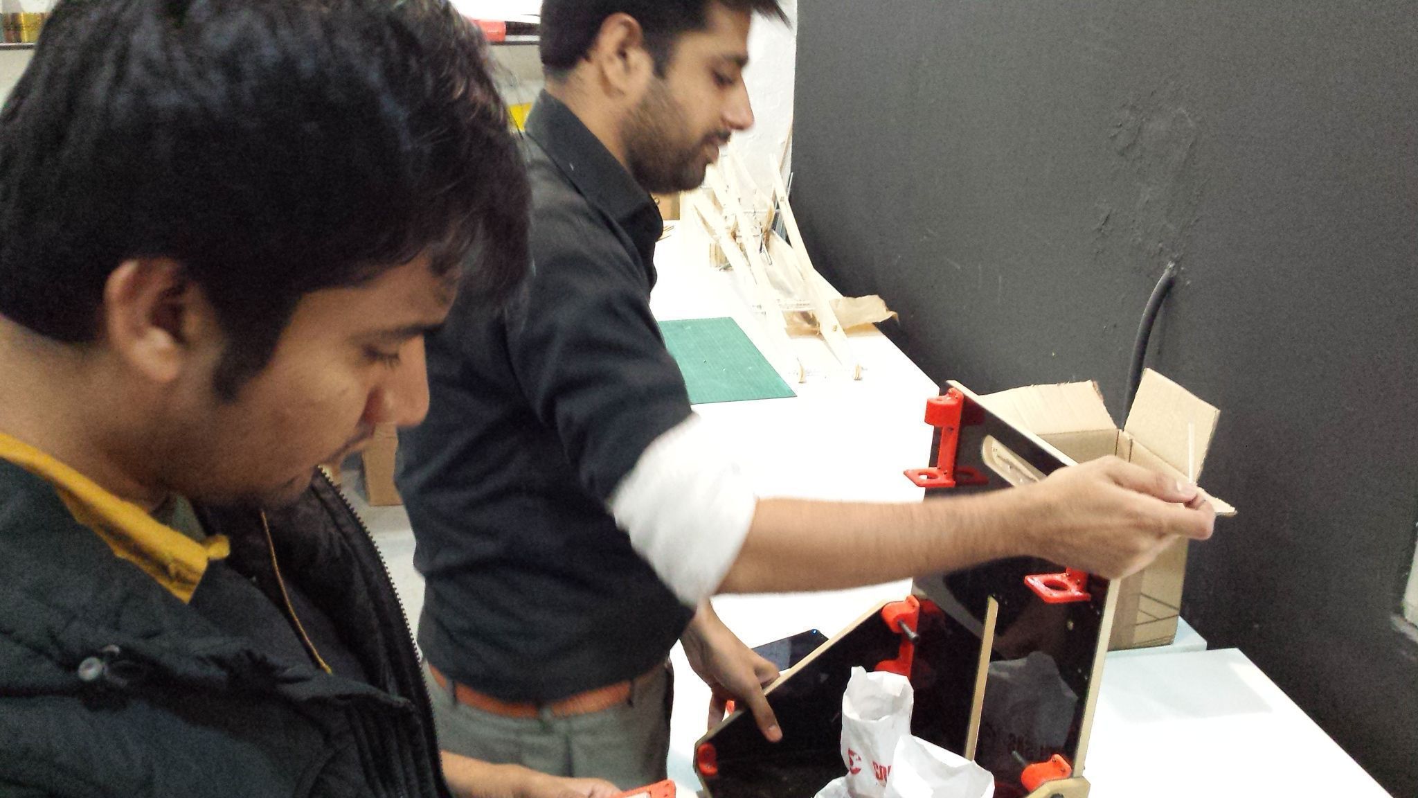
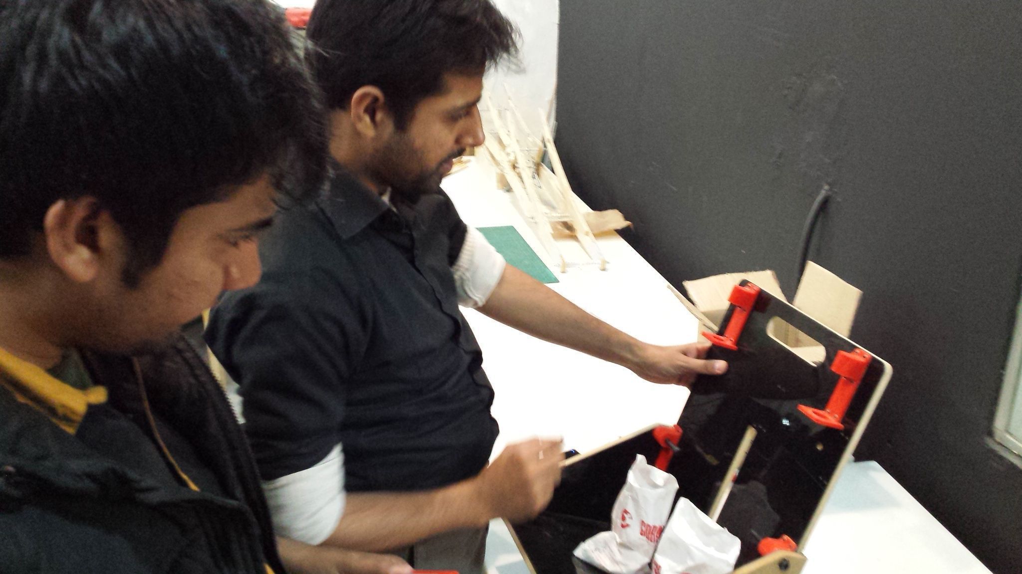
Finally I also took some part for the final assemblly of all the components to build the this 3D printer like placing the parts to their exact position.
You can download all the files by clicking the link below
IGES files STL files