An electronic adjustable wrench
The idea of my final project is to develop a wrench adjustable through electronic components listed below. An adjustable wrench is an open ended wrench with one fixed and other adjustable jaw. Wrenches are mostly sized in inches or metric mostly household repairs go with measurments in inches and if you do alot of auto work you will definitly be needing metric set. Most of wrenches with jaws are coming with manually adjustable unit I mean the jaws are being adusting through sliding the nozel up and down as shown in figure below but in my project I want to replace this manual adjustable unit by electronic adjustable unit.

My Idea
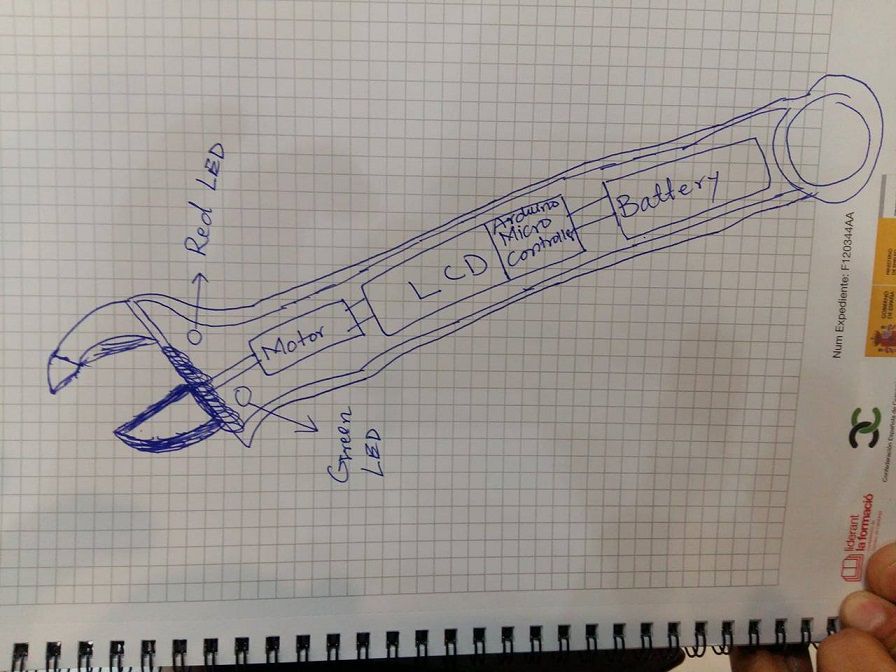
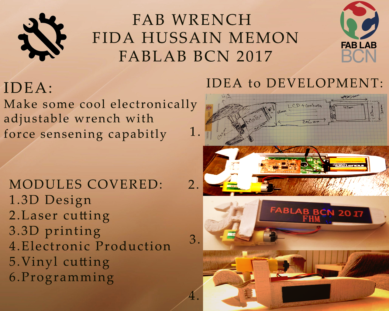
The basic purpose of this idea is to open the adjustable jaw of the wrench through Dc motor that is controlled by arduino powered by dc supply battery of 9 volt. An LCD is also interfaced to show the exact measurment of opening space of the jaw and other necessary actions. One on/off button is there for powering on and off the device and one force sensing resistor is there to confirm the amount of force for tightening the bolt.
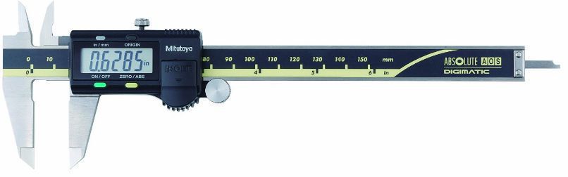
I was inspired from the measuring device mostly found in scientific labortaries by name vernier caliper. previously it was found in analog measurement method but now days it is available in digitally reading meter embded over the analog scale of the vernier caliper as shown in figures below
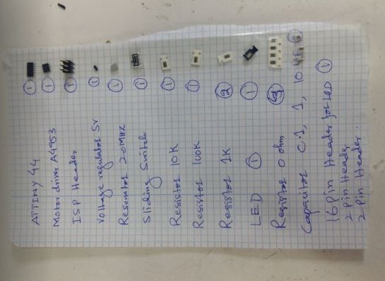
Components required
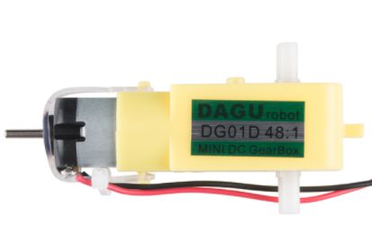
DC Motor
The purpose of the DC motor in my project is to open and close the movable jaw according to the programmed value of the force sensor. this is 9v dc motor and I m using H-bridge A4953 as Dc motor driving IC in final circuit
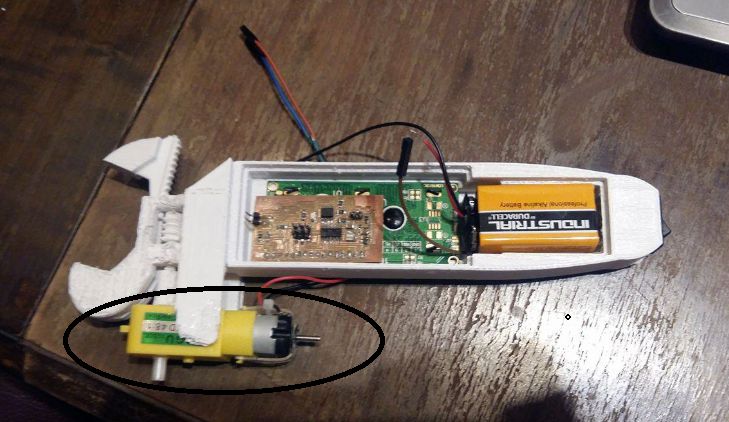
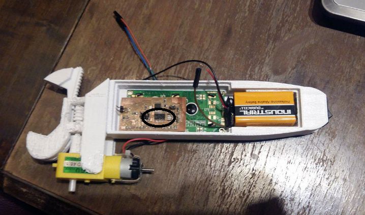
The DC motor placement in my final project
I have already controlled the motor using same controller in my assignment of Week 10
9 Volt Battery
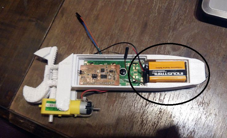
The Duracell Procell 9 Volt Alkaline Battery will be used to power up the main circuit baord. this battery is easily available in electronics shop and online as well. It has a rectangular prism shape with rounded edges and a polarized snap connector at the top and I will be needing one battery cap with terminal cables to connect this with main board.

The 9V battery placement in my final project
LCD display
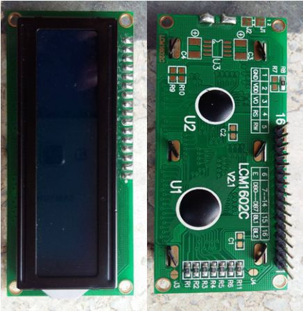
In this project a 16 coloumn by 2 rows liquid crystal display will be needed to display the measuremnets and other necessary actions performed by this device. This lcd was already available in the Fab lab and it is easily available commercially at very convinient price. The model 1602 lcm is very bright with contrast controlling pin I thoroughly went through the data sheet of this lcd to understand the pin out configuration and other necessary information related to funtionality of the device. I already performed lcd control during my 10th week assignment a detail information regarding this is avaiable there.
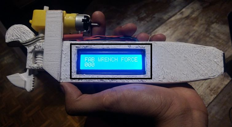
The Lcd placement in my final project
Here is the video demonstration of Week 10 showing the funtionality of lcd that is basically controlled by pcb board containing Attiny 44 controller as it microcontroller
ATTINY 44
The high-performance, low-power Microchip AVR RISC-based CMOS 8-bit microcontroller combines 4KB ISP flash memory, 256-Byte EEPROM, 256B SRAM, 12 general purpose I/O lines, 32 general purpose working registers, an 8-bit timer/counter with two PWM channels, a 16-bit timer/counter with two PWM channels, internal and external interrupts, an 8-channel 10-bit A/D converter, a programmable gain stage (1x, 20x) for 12 differential ADC channel pairs, programmable watchdog timer with internal oscillator, a internal calibrated oscillator, and three software selectable power saving modes. By executing powerful instructions in a single clock cycle, the device achieves throughputs approaching 1 MIPS per MHz, balancing power consumption and processing speed. for its data sheet refer my assignments in week 6 and week 8.
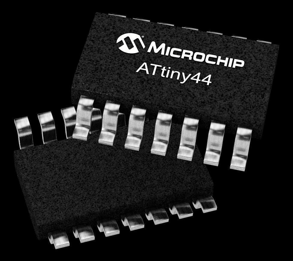
The controller placement in my final project main board
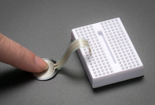
Force sensor resistor (FSR)
A force-sensing resistor is a material whose resistance changes when a force or pressure is applied. They are also known as "force-sensitive resistor" and are sometimes referred to by the initialism "FSR".
FSRs are sensors that allow you to detect physical pressure, squeezing and weight. They are simple to use and low cost. This sensor is a Interlink model 402 FSR with 1/2 diameter sensing region. FSR's are basically a resistor that changes its resistive value (in ohms Ω) depending on how much its pressed. These sensors are fairly low cost, and easy to use but they're rarely accurate. They also vary some from sensor to sensor perhaps 10%. So basically when you use FSR's you should only expect to get ranges of response. While FSRs can detect weight, they're a bad choice for detecting exactly how many pounds of weight are on them.
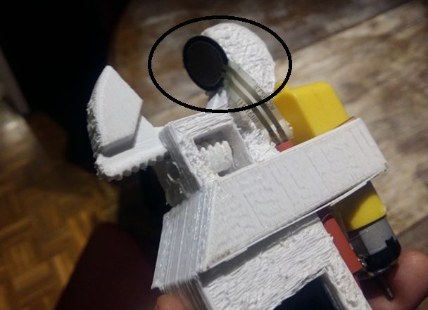
The placement of FSR in my final project
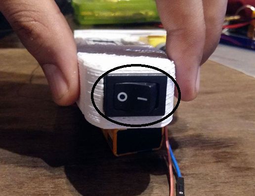
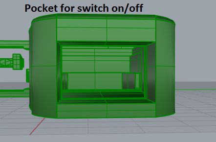
On/Off Switch
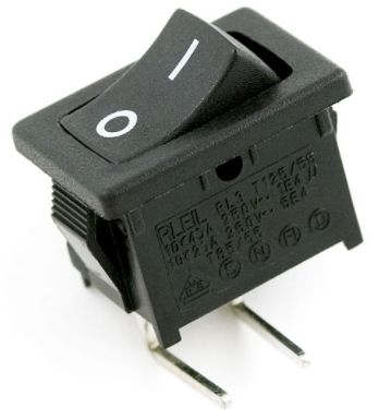
The placement On/Off Switch my final project
Bill of materials
1. LCD display (1.5 euro click here for the link)
2. Force sensing resistor (8.32 euro click here for the link)
3. DC Motor (4.99 euro click here for the link)
4. 9v Battery (1.5 euro click here for the link)
5. 3D printed casing including laser cut ecrylic sheet (approximately 2 euro)
6. 3D printed gear part (approximately 0.5 euro)
7. Microcontroller based circuit (1 euro, www.digikey.es)
8. Miscellaneous resistors and capacitors as per requirement of circuit(approximately 3 euro, www.digikey.es )
9. A switch button (0.75 euro from diotronix Barcelona)
Total cost = 24 euros lumpsum
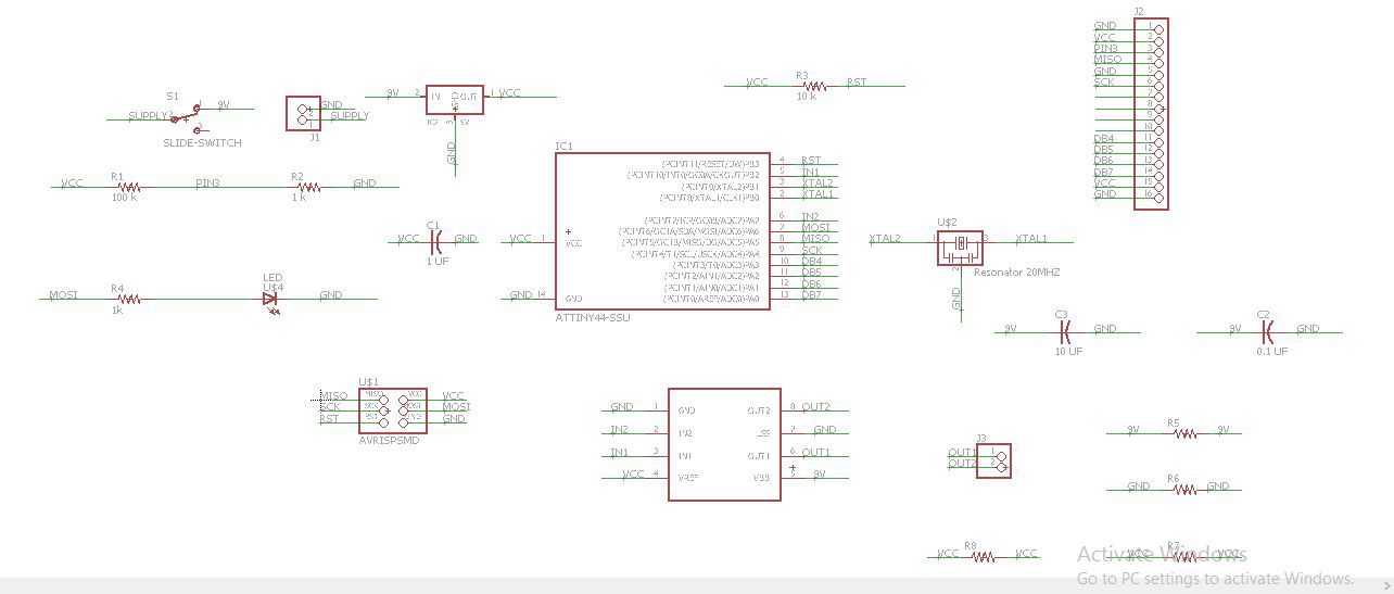
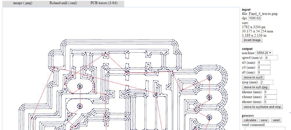
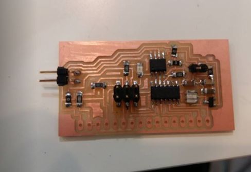
Developing the PCB using Eagle
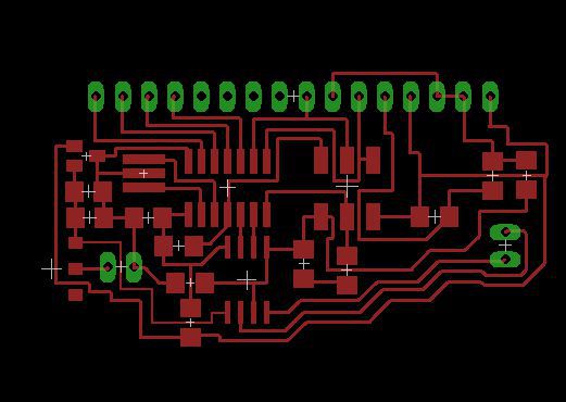
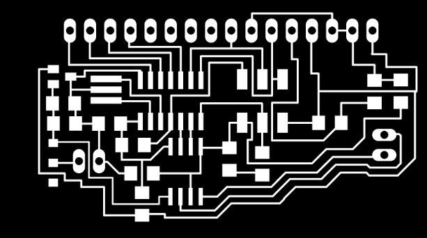


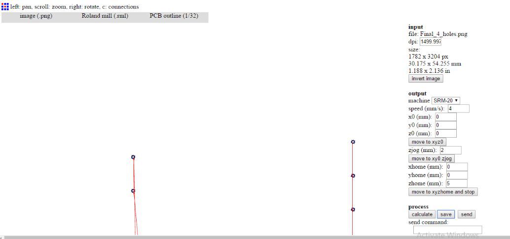
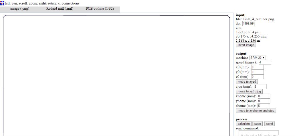
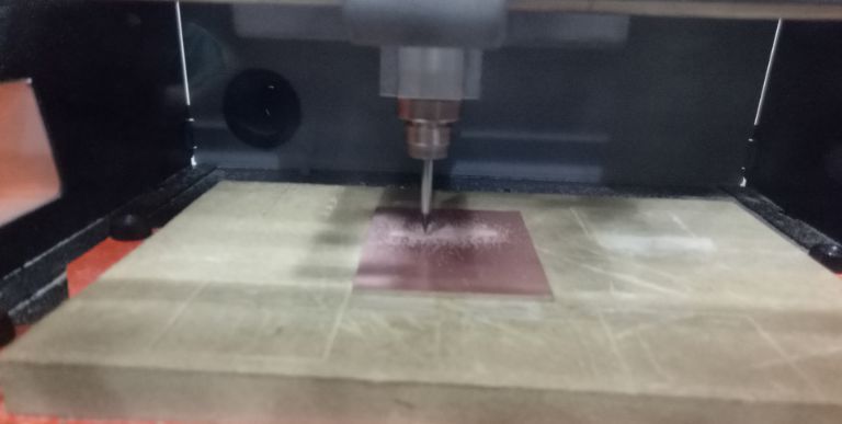
Milling the board
Populating the baord with components
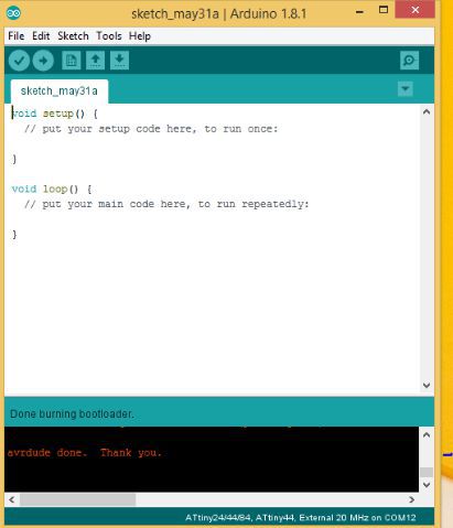
Burning bootloader
Soldering the LCD with main board
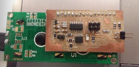
Testing LCD functionality
Testing DC motor functionality
Testing force sensing resistor
After testing all the components to be interfaced with the final board I reallized that I have done with the electronics portion of the final project so its time to fix the design model for the wrench, previously I started to design the wrench in Solid works and in parallel with Rhino also but not with exact dimensions of the components to be assemblled. I redraw my initial concept and putting the components to observe the exact dimensions.
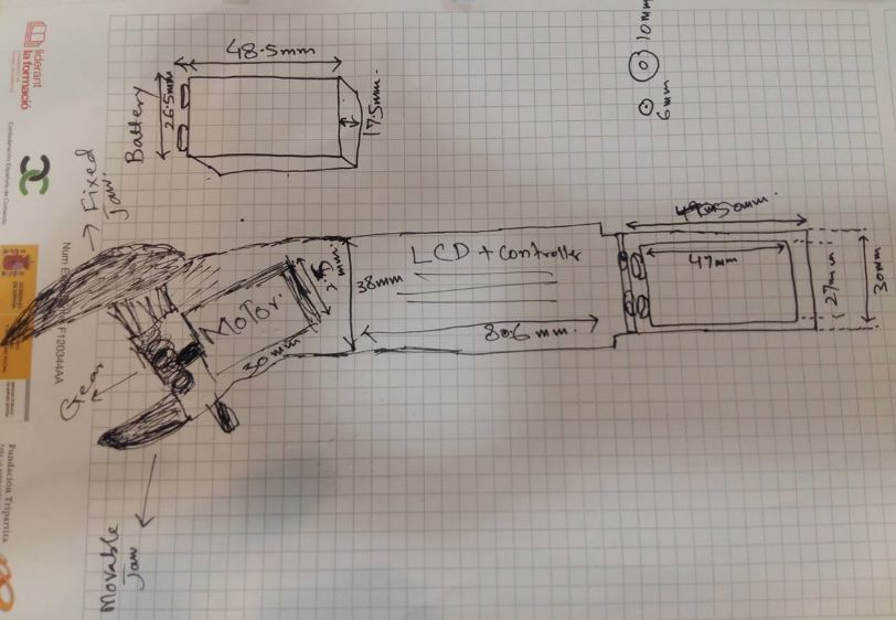
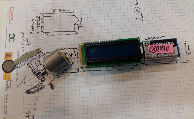
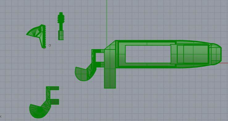
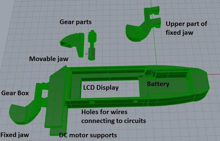
Developing the 3D model with exact dimensions using Rhino
I started design my 3D model for the final wrench product using rhino. it was quite interesting learning experience while designing working on several layers and and using different commands finally I got following design ready for the 3D printing. I start working over designing of this wrench from Week 2 but as I was newbie to all these designing softwares that time so I could finithe final design during my final project pregression period
Video demonstration of 3D printing
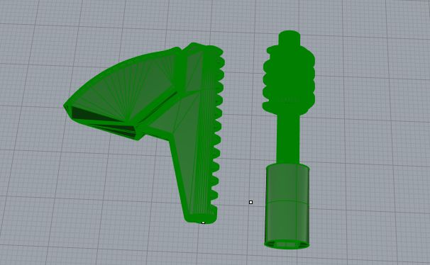
This was final 3D printed casing which become usefull for my completion of wrench but before this I tried 2 to 3 times 3D printing which did not become fit for my circuit specially for the gear part it was rquiring fine tuning while printing it so following some videos are the 2 to 3 tries to get the fine design
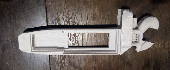
Final 3D printed out Casing
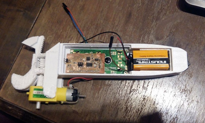
Assembling Casing and all electronics
Programming code for final project
				//#include
#include
#include
LiquidCrystal lcd1(5,4,3,2,1,0);
 int flag = 0;

int x, d1,d2,d3 = 0;
int sensorValue = 0;

//SoftwareSerial mySerial(5, 10); //Rx, Tx

void setup()
{
  pinMode(A6, INPUT);
  //digitalWrite(A6, HIGH);
  pinMode(7, OUTPUT);
  pinMode(8, OUTPUT);
//  mySerial.begin(9600);
  //while (! mySerial);
  lcd1.begin(16, 2);

      lcd1.clear();
       lcd1.setCursor(0, 0);
      lcd1.print("FAB WRENCH FORCE");

}


void loop()
{


  int sensorValue = analogRead(A6);


  int binbyte = sensorValue;
  x = binbyte/10;
  d1 = binbyte % 10;
  d2 = x % 10;
  d3 = x / 10;

    lcd1.setCursor(0, 1);
    lcd1.print(d1);
     lcd1.print(d2);
     lcd1.print(d3);

  if (flag == 0){
            digitalWrite(8, HIGH);
          digitalWrite(7, LOW);
          delay(1000);
          digitalWrite(8, LOW);
          digitalWrite(7, LOW);

          flag = 1;
          }

          if (sensorValue > 10 && sensorValue < 400){
          digitalWrite(8, LOW);
          digitalWrite(7, HIGH);}
          else if (sensorValue >= 700){
                    digitalWrite(8, LOW);
                    digitalWrite(7, LOW);
            }


           delay(500);
        }