Computer-Aided Design
This week assignment is to explore the some 2D and 3D modelling software and simulate a possible final project model in some of these software.
The learning outcomes for this week are to Evaluate and select 2D and 3D software to demonstrate and describe processes used in modelling with 2D and 3D software.
2D Software
1. Photoshop (as a raster)
Photoshop is most advanced image editor software, being a beginner of using this software I first of all followed the video tutorial available on youtube given below. I then started to edit the initial idea of my final project. this software provides many image editing features for raster also known as pixel based images, it contains layers based editing system that enables image creation and altering with multiple overlays that support tranparency. This software is mostly used by photographers, graphic designers, video game artists and advertising agents.
Tutorial I followed
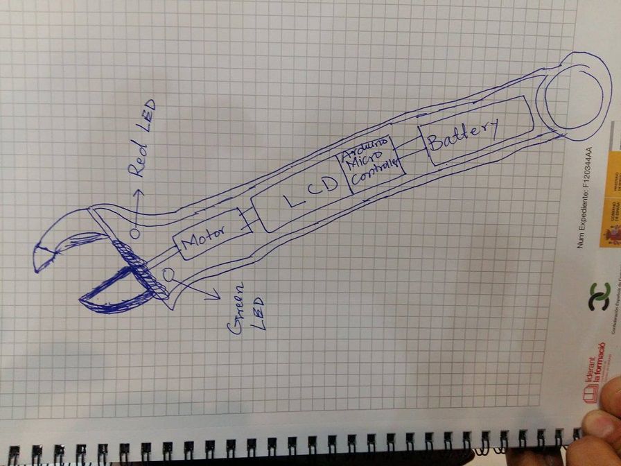
I designed the initial sketch of my final project layout which is shown below. At first I drew the idea on paper and then followed the same on photoshop
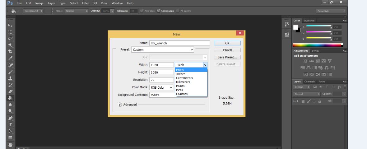
Getting started with PS
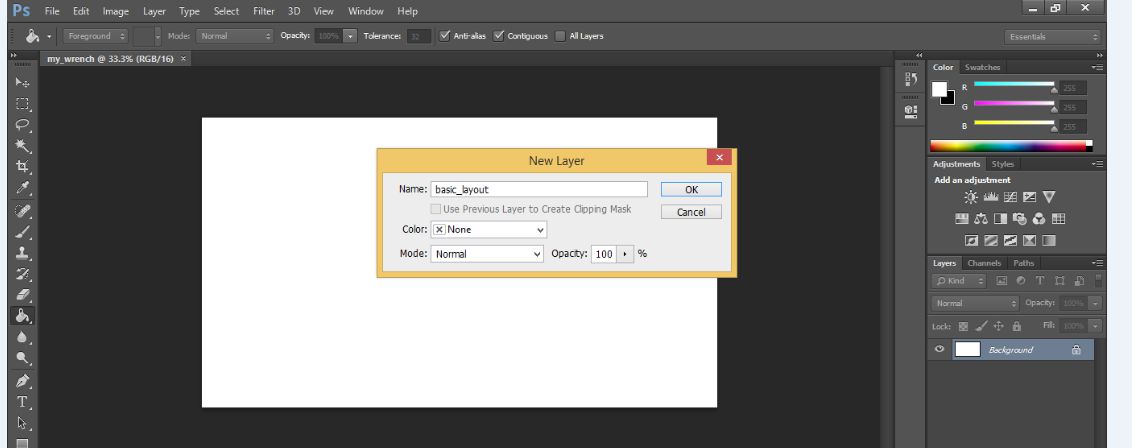
As photoshop works on layers for every action adding something to image or text to be edited to the specific look, following image is showing how introduce the layer.
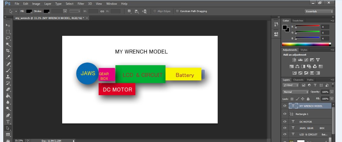
Here I m adding some blocks assigning different colors to each in order to distiguish the different segments of project
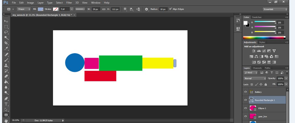
At this stage I became some how use to this raster based software and developed my initila idea of project in it as under.
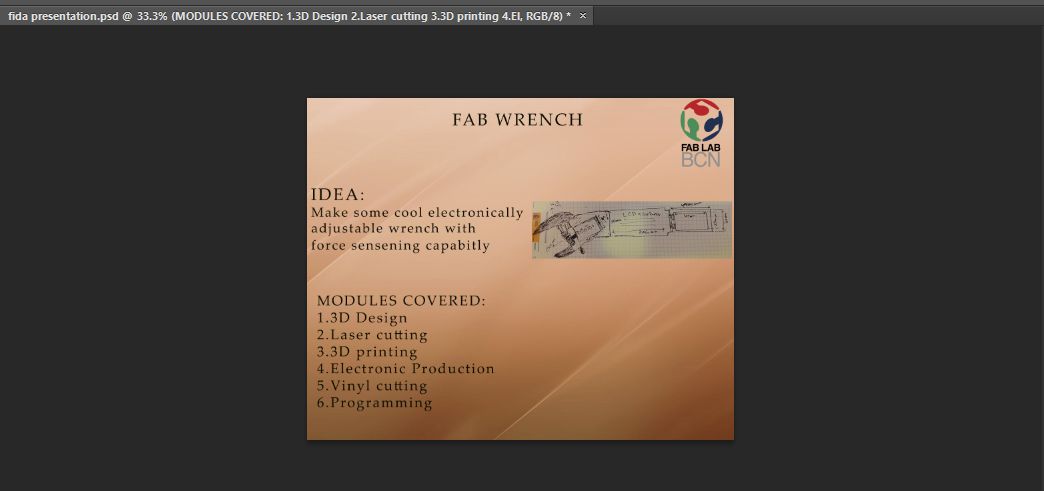
Further more I also designed the simple poster for the final presentation.
2. Inkscape (as a vector)
Similer to photoshop I was also a newbie to use inkscape, but by following my instructors and along with some video tutorials I realised my self use to a little. The inkscape is a professional quality vector graphics software that runs almost in every operating system, this software uses W3C and SVG (Scalable Vector Graphics) as its native formats and widely used to creat variety of graphics such as illustrations, icons, logos, diagrams, maps and web graphics.
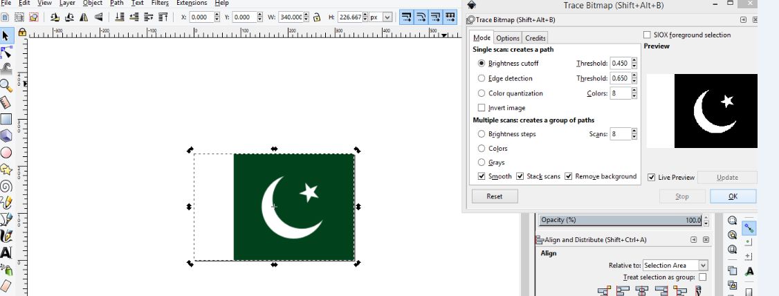
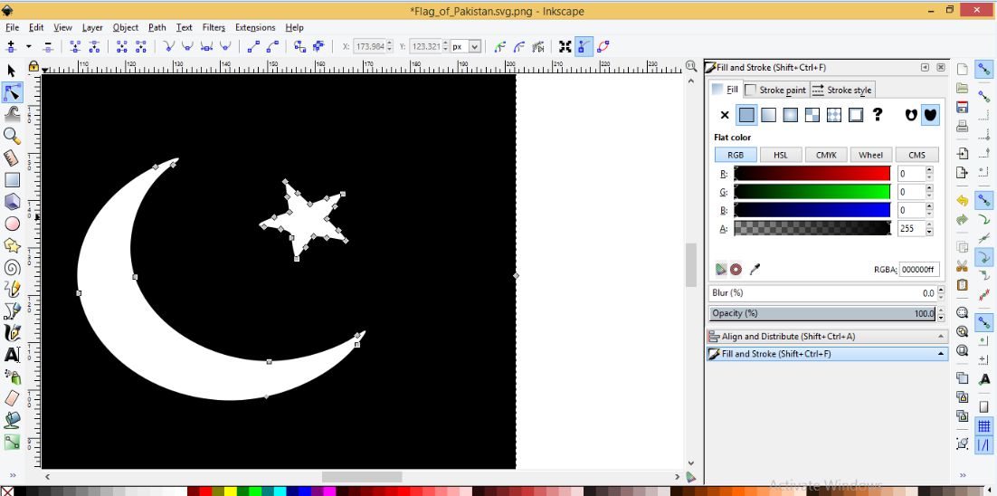
At first I import the picture of pakistan flag into inkscape and apply the trace Bit map (Shift+Alt+B) and did some specified settings as shown in the image below.
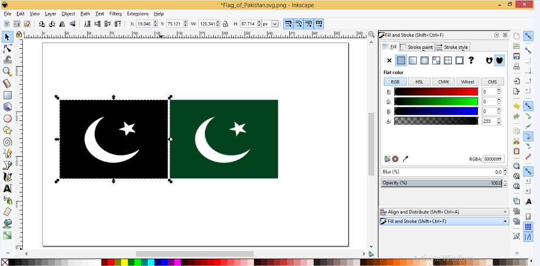
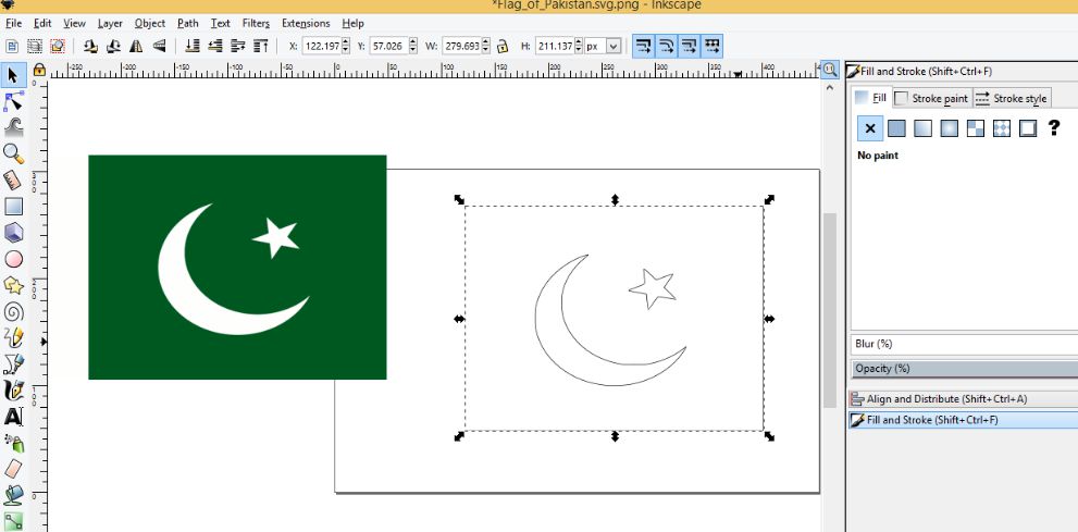
After that I applied fill and stroke command (Shift+ctrl+F) and observed following changes
Edges detection
3. Rhinoceros
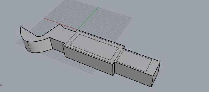
This time I tried to develop my final project model in Rhinoceros, though my design looks not so cool as it should be but just to become familier with the software I applied very basic commands to achieve this. Using Line, distance and some other related geomatrical commands available in this software I achieve the top view of the project as under.
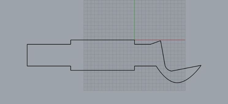
Adding some pockets for putting different devices to used in final project
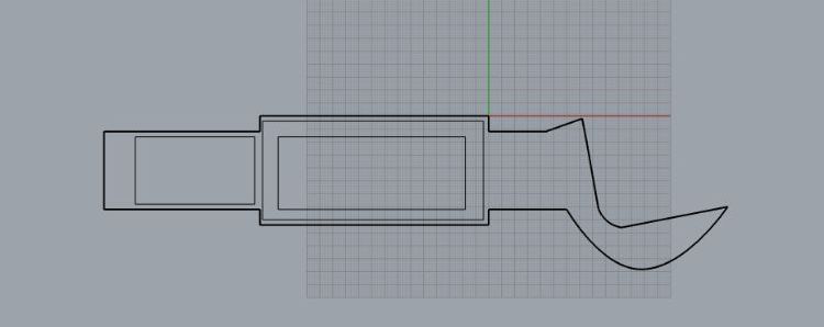
Joining all the curves to make this one object and then Extrude command is applied up to specific distance and here is the view in prospective window
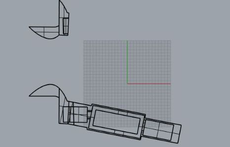
Designing the movable jaw in the same way with different geomatrical dimensions
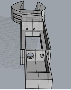
Finally joing all the peices and here is model look like
4. Solid works
I completely follow the tutorial I fount on youtube to design initial phase of final project. I learnt alot from this tutorial and by following it I came across to design different solid parts required in assemblly of complete product
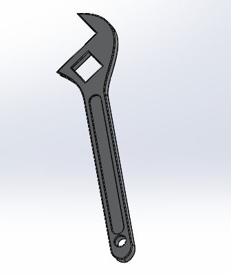
Starting with drawing lines and some angles to achieve a 2D curve or sketch of wrench. In solid works I m able to customize my design to my specific dimensions using smart dimension command in solid works

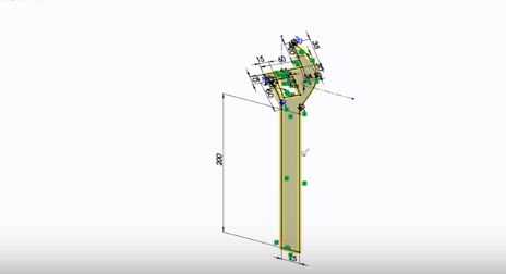
Extrude the surface to view the solid wrench
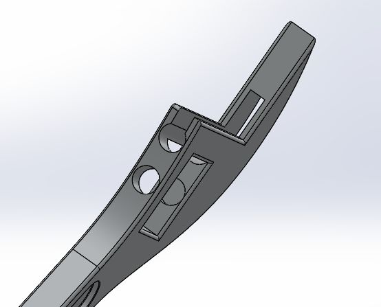
Using extrude and champher commands I made some through hole pockets to fit gear part it
Designing the movable jaw
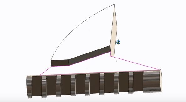
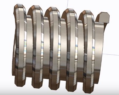
Gear part
Download useful files here