Output Devices
This week is about output devices and we were assigned to add an output device to the board we designed in week 8. In the lecture Neil shows us different output devices for connecting with the board we developed in previous assignment ss I was interested to connect LCD as my output device because I wanted to learn the interfacing of LCD with Arduino or other board we are making during this diploma. Interfacing LCD is also a part of my final project so I decided to interface the LCD with board. I m really thankful to all the instructors for guiding me in proper way to accomplish this assignment.
Task Assigned
Add an output device to a microcontroller board you’ve designed and program it to do something.
Learning Outcomes
- Demonstrate workflows used in circuit board design and fabrication
- Implement and interpret programming protocols
I took Neil's board as a referrence and redisgned that in eagle for the interfacing of LCD. The components I used to design this board were all available in Fab Lab inventory. Mean while I started to read the data sheet of ATTINY44
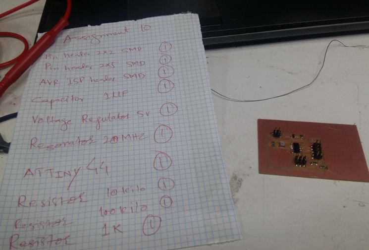
To develop the board I was needed the following components as listed.
- ATTINY 44 Micro Controller (ATTINY44-SSU)
- Voltage Regulator (REGULATORSOT23)
- Three resistors 1K, 10K and 100K ohms (RES-US1206FAB)
- AVR ISP SMD (2*03SMD FAB)
- Two Pin headers 2*2 SMD(PINHD-2*2-SMD) and 2*5 SMD(PINHD-2*5-SMD)
- Resonator (20 MHz)
- Capacitor of 1 Micro Farad (CAP-UNPOLARIZEDFAB)
To interface LCD with the board I was going to develop I needed a LCD and to understand the process of communicating this device with the board so at first I took a LCD available in the lab as shown and went throught its data sheet specially its pin diagram. I used LCD with model number LCM1602C (data sheet)
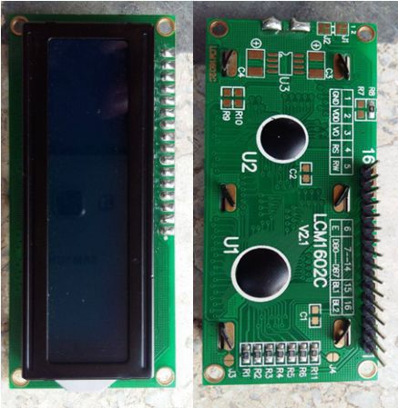
While analyzing the data sheet I came to know about the function 16 pins of LCD. Among those sixteen pins 1st and 16th pins are to be grounded, 2nd and 15th pins are VCC pins, 3rd pin is for contrast adjustment and I used 10 kilo ohm potentiometer with this pin to adjust the contrast of LCD light, 4th pin is Register select that selects registers between instruction register and data register, 5th pin read/write pin which is being kept read/write instruction, 6th pin is enable pin which kept logically high so that LCD is processing the incoming data.
There are 8 data pins D0 to D7 in LCD and these range from Pin 7 to 14 of LCD. These are also called 8 data bus lines to perform read/write of the data. Commoly LCD receives the data in two types of data modes 4 bit data mode and 8 bit data mode respectively in my I have communicate the LCD with my board via 4 bit mode so I m using 4 data pins or data lines i.e from 11th pin to 14th pin (DB4 to DB7) and ultimately I m not sending any data on the remaining 4 data pins but I m supposed to communicate the LCD using 8 bit mode then I have to utilize all the 8 data lines.
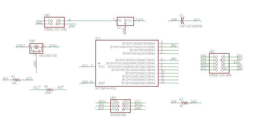
Now lets start to develop the board. I followed Neil's board and using eagle software I redesigned the schematic of the board using Fab library already integrated in my eagle software. following is the image of Schematic.
Schematic
Final Board Design
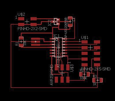
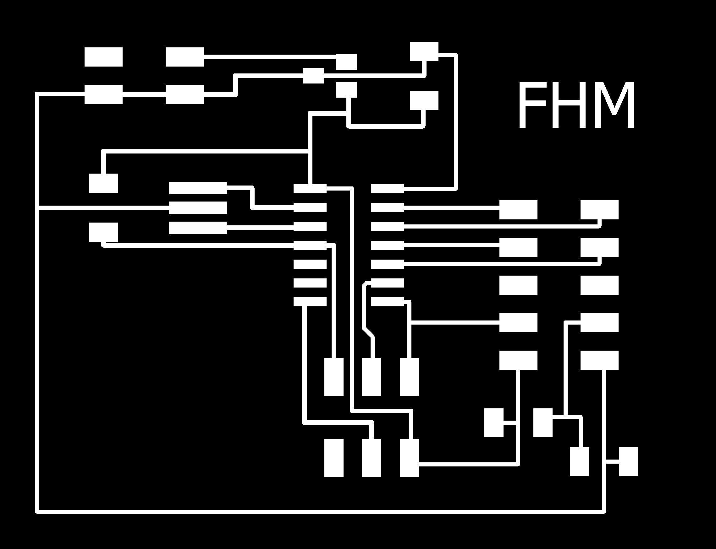
Traces
Outline

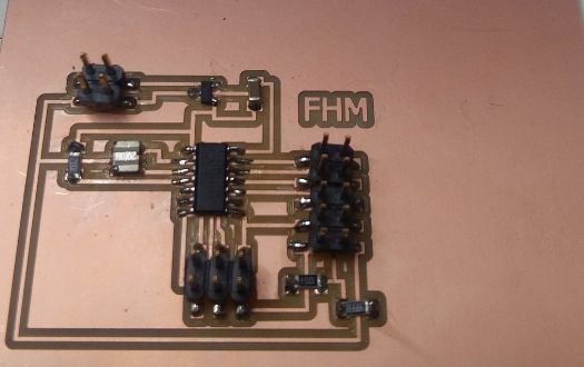
Now its time to mill the board. Using same Fab modules I generated .rml files for Traces and Outline, both files will be available at the end of this page. I used Roland milling machine SRM-20 and milled the board and got finally the following board and populated that with components required .
LCD interfacing with Arduino UNO
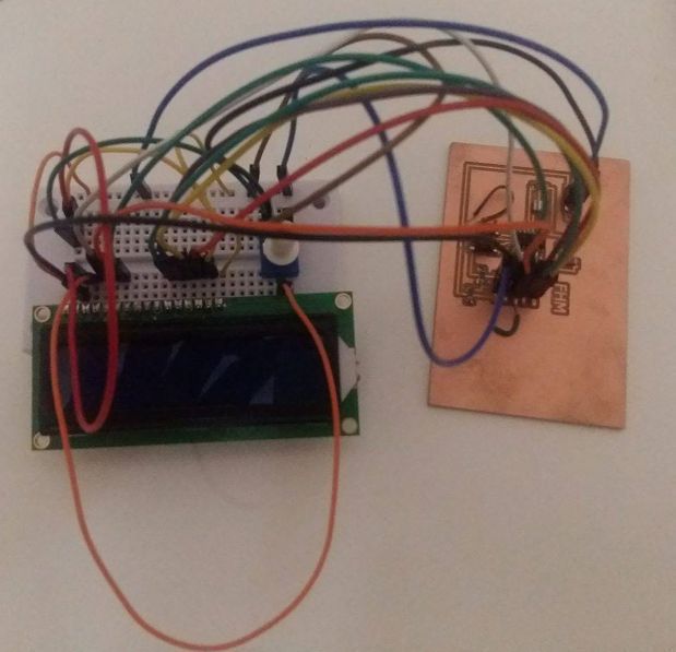
Though my board was ready to program and then interface the LCD for displaying something but before using my board I tested the LCD by interfacing with arduino UNO by compiling my own simple C code in IDE, here are some snapshots of the display.
Programming the Board
I programmed my board using my ISP programmer which I developed in week 4. initially it did not work and I checked my board and found some disconnectivities in the board as shown below in the image.
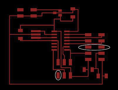
Observing these situations on the board I thought of developing the board again but I tried to diagnose the issue using some jumper cables and then I programmed the board and obsereved that my board was succesfully programmed and I did not go for mill again the board.
Interfacing LCD with the board
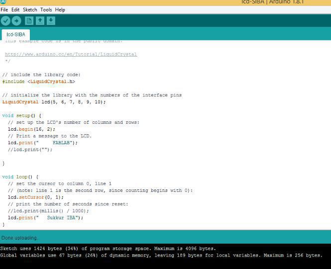
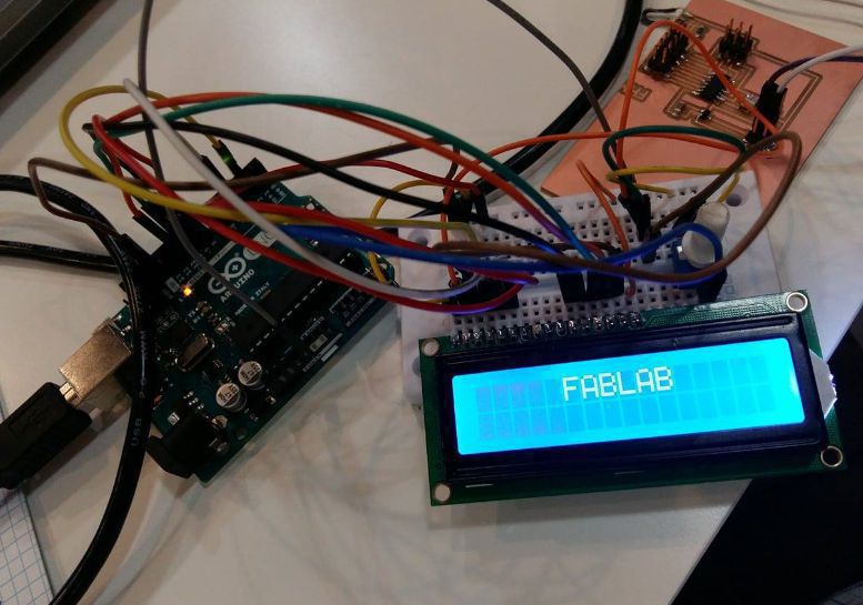
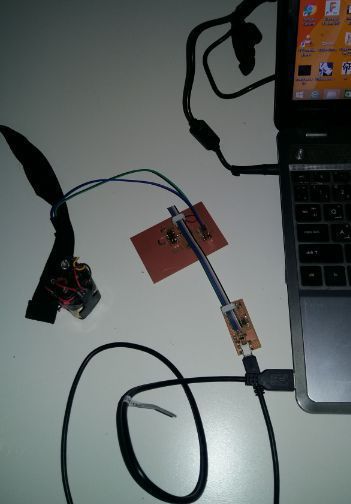
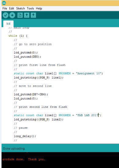
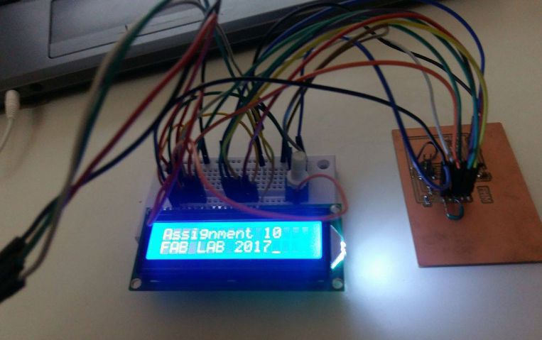
Finally its time to interface the LCD with board to find some display on it. I used FTDI cable to give power to the board and interface the LCD with my board as per pin specification. I burnt the Neil's Program by changing some text statements in my board and observed following successful results.
Connections
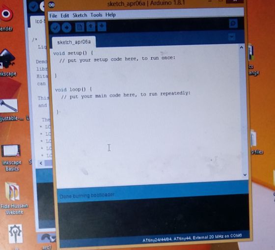
Program Uploading
Output
Demo
During this I was also working on my final project circuit board as I was aimed to develop an adjustable wrench so I need to interface the DC motor also with Lcd this Dc motor is sopposed to be used to open and close the adjustable jaw of the wrench so I used my final project circuit board in which I have used A4953 H-bridge as dc motor driving IC. Following video I have uploaded is demonstrating the functionality of Dc motor working with the Lcd and an on/off switch is also integrated to start or stop the function at this stage later on I will also connect force sensing resistor.
Video demonstarion for Lcd and Dc motor together
I have uploaded more useful files related to the code and schematic of board that is controlling Lcd and dc motor together on my final project page you can download the files from there. By clicking here you can access my final project page.
Download Useful files here