
Assignment
Make a machine, including the end effector, build the passive parts and operate it manually.
0.Idea
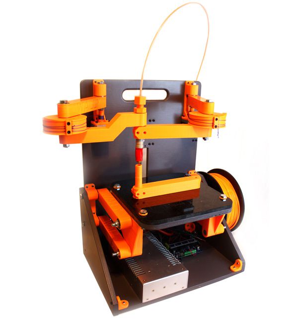
We want to make a wally 3D printer.
1.Introduction
So for this week is concerned, its all about Group Asssignment to develop a machine that makes (the machine). It was quite a new experience for all of us to work together in a group to develop something. Initially we planned some meetings to come up with an idea of a machine that we can make. Finally after some due delibration we decided to make a special type of 3D Printer generally called "Wally".
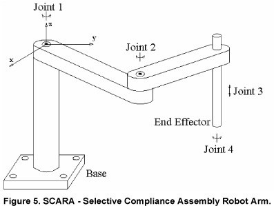
Wally is a wall bot where everything is mounted on the wall. Wally is a variant of reprap 3D printers which belong to Selective Compliance Assembly Robot Arm (SCARA) family. The idea was to make Wally as simple and low cost as possible, and use much less plastic and bearing than other does, but has faster speed and better resolution.
The printed parts take almost 1kg of PLA and 40-45 hours to print a complete set. Nicholas Seward recommends PLA printed at a 0.3mm layer height and 15% infill with 3 perimeters.
RepRap Community is working for the portable and replicable 3D printers. RepRap is humanity's first general-purpose self-replicating manufacturing machine. Since many parts of RepRap are made from plastic and RepRap prints those parts, RepRap self-replicates by making a kit of itself - a kit that anyone can assemble given time and materials.
2. Details about the concept:
- Built off a rigid back board. The board can have ribs attached to make it more rigid. The material is TBD based on prototype needs.
- Wally could be designed to fold fairly flat for storage or portability. Think suitcase with a handle on the side. Legs could fold out to make it free standing, or it could be attached to a wall.
- The design can be scaled. Perhaps a 12" backboard width at the small end. That might give more than a 6" cube build volume. A 15" backboard width might give something on the order of 10" Diameter, or an 8" square, or a 10" x 7" Rectangle -- all with a 10" height. I think this would be a good design center.
- All axis are driven from stepper motors through a Spectra fishing line drive on preferably smooth pulleys.
- The two X,Y arms are driven by rotating the elbows. This gives a build area that is limited by an arc from the shoulder with a straight elbow to the hot end.
- The ratio of the stepper drive to large elbow pulley determines the resolution and torque. 0.025mm or better with a reasonable ratio with a 16-32x microstep.
- The Z axis is a 4 bar linkage that keeps the bed flat as it is rotated up and down through an arc. Gravity lowers and a stepper winding a string raises it.
- The build platform moves through an arc as the Z is changed. The X,Y arms have to compensate for the displacement in the Y axis (perpendicular to the back board).
- A convenient place for a spool is on the lower back. Filament would be fed up through a Bowden extruder and over the top and down to the hot end.
3. Features
- No linear rails
- 28 cheap 608 bearings
- 12 unique plastic pieces (none require support)
- Printable on a 150x150mm machine
- Theoretical speeds in excess of 500mm/s
- Theoretical resolution is less than 25 microns
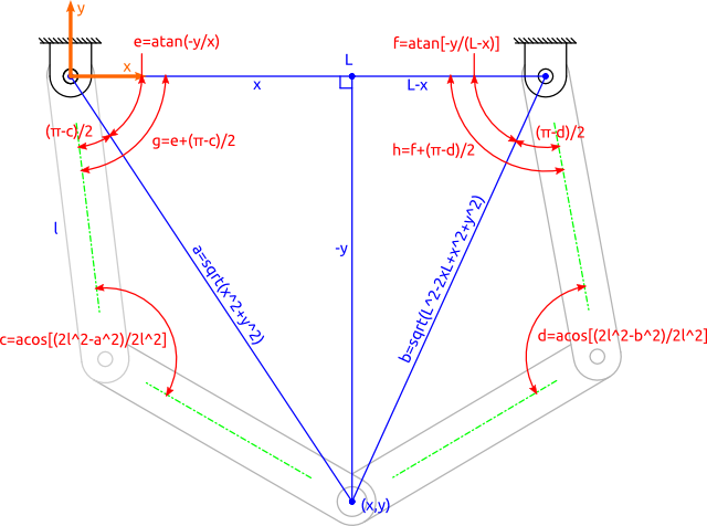
Wally works on inverse kinematics, In robotics, inverse kinematics makes use of the kinematics equations to determine the joint parameters that provide a desired position for each of the robot's end-effectors. Specification of the movement of a robot so that its end-effectors achieve the desired tasks is known as motion planning.
Once the idea was ready, now its time to divide the task and get started
4. Task division
- Develop the Wooden Frame, Electrnoics and Programming - Fida Hussain
- XY axis Mechanical Assembling, Wireless Communication - Muhammad Asim
- XY axis Mechanical Assembling, Preprocessor Programming - Nisar Ahmed
- Z Axis Mechanical Assembling, Electronics and Programming - Sohail Ahmed Soomro (its me :))
- Hot End Extruder Management, Electrnoics, Electrical and Mechanics- Tomas
5. Frame Desgning
We started our work, first one was Fida, his task was to cut and assemble frame so that we can further proceed. we can find the details of this section here on our group page
All the 3D files related to Wally are available to download from here:
6. XY Axis Working
Once the frame was ready now it was the time of print the XY and Z axis components their assembly.
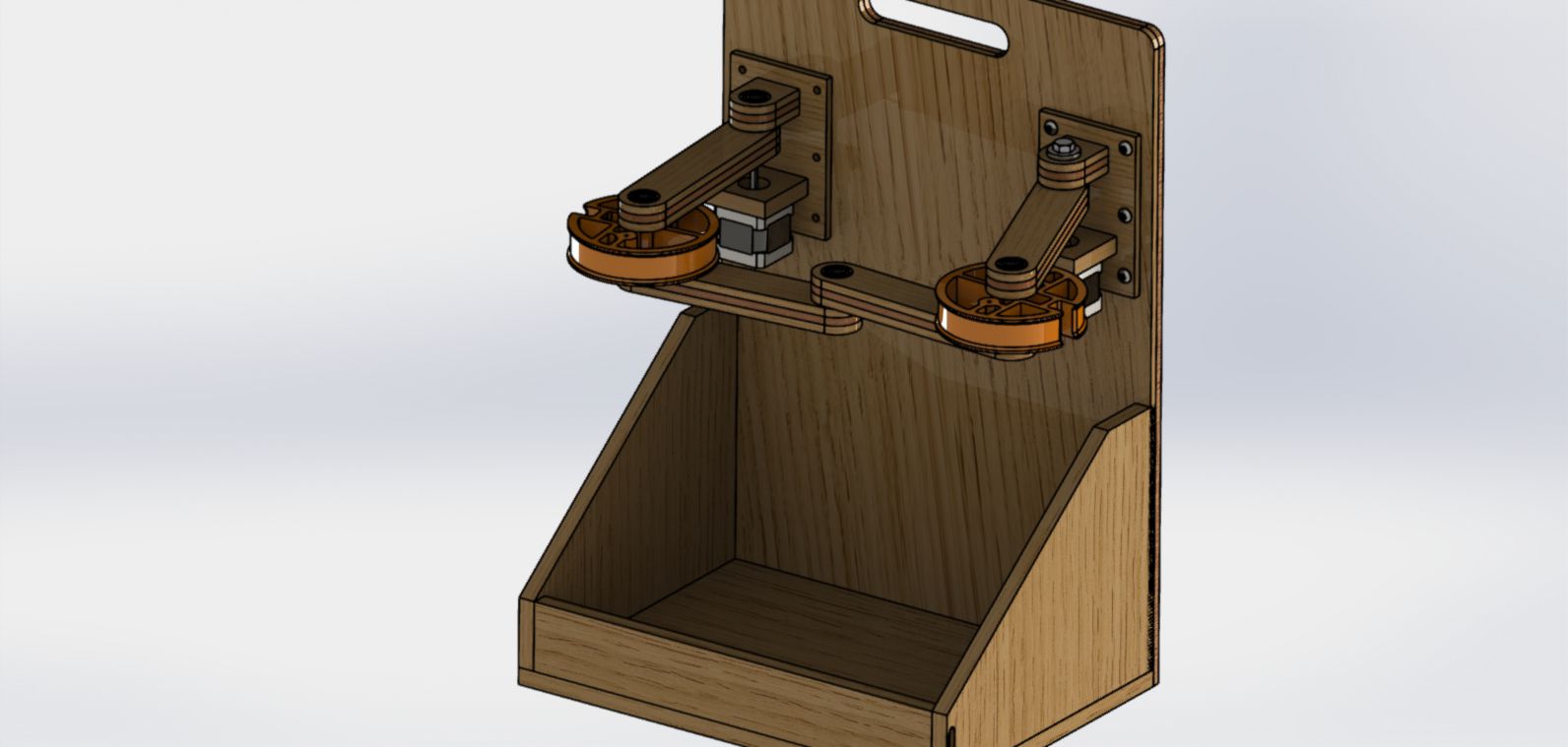
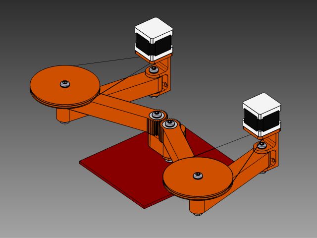
Wally places the stepper motors on the walls of the frame to reduce the wieght and allow the arm to move at faster speeds. The position of the arms is adjustable through fishing line drive belt as illustrated below.
The mechanical assembly of XYh movement axis required are printed by my other groupmates. we can find the details of this section here on our group page
7. Working on Z-axis of Printer.
My Part in this project is to 3D print all the components required for the z-axis assembly of wally and assemble it in the main body of the printer.
Following video will help to understand the movement of wally printer. The video given below shows the movement of the Printer and including the z-axis movement.
As we that the wally printer is with a parallelogram constrained build bed elevation with no linear bearings and no timing belts, so the First we will need to understand the parallelogram movement. The following video help us to understand the simple parallelogram movement.
In actual printer, the movement is bit different from the above video. The following figure shows the exact movement of the bed along z-axis in wally printer.
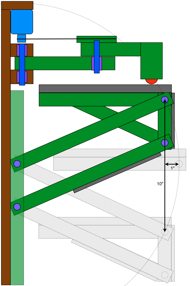
From the above figure, we can see that in this case bed is moving in arc not in straight line. So, that is why I am curies to see the that how we will be able to accommodate this arc movement of bed while interpolating the GCODE.
Now the next step is to 3D print all these parts required for bed movement.
7.1 3D printing of the components.
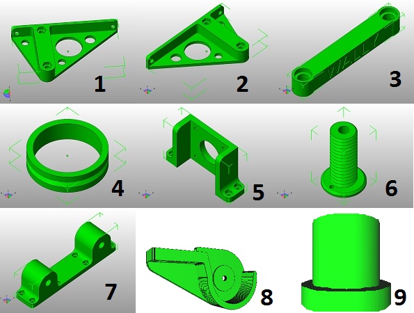
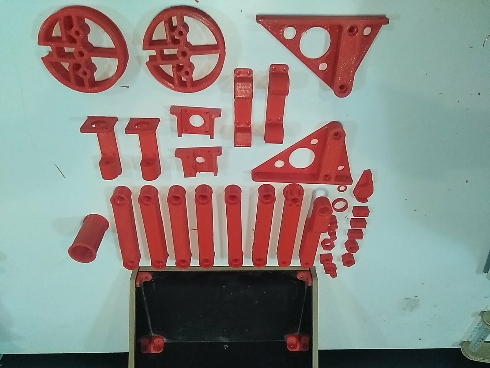
We need lots of part to move bed in the printer along z-axis. The list of parts is given below that I have 3D printed. The complete list of components for the printer can be seen HERE
- 1. Bed Bracket right
- 2. Bed Bracket left (Mirror of right)
- 3. Arms
- 4. Idler for Z-axis
- 5. Motor mount
- 6. Pulley for Z-axis
- 7. Z-axis wall brackets
- 8. Pulley holders
- 9. Idler holder
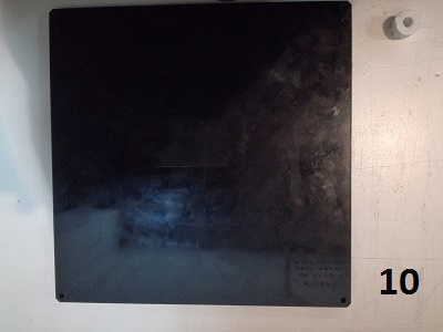
- 10.Bed
The Next step is to import all STL file one by one in Cura and generate the GCODE file of each of the file shown above and copy those files to SD card and print all files.
Detail settings of Cura and 3D printer are given in Assignment of week 3 or Click here(http://archive.fabacademy.org/archives/2017/fablabbcn/students/342/week5.html)
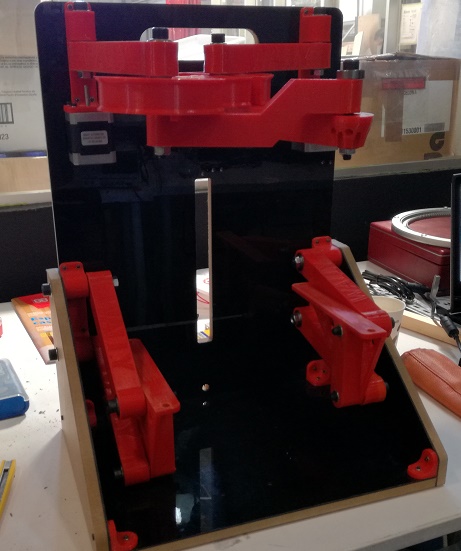
All parts of printer is ready now.
Before assembling there is another thing that we need to do is to fit the nuts and barring in the parts of the printer. For this we need to use solder to melt the PLA little bit to fit the barring and nuts. Following pictures shows the process.
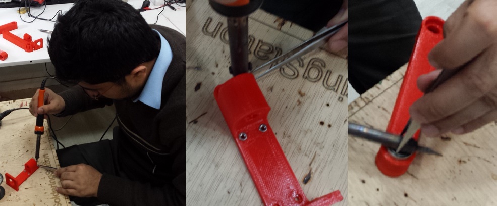
After doing this we are ready to assemble the model.
Download All file of this week from Here

This work is licensed under a Creative Commons Attribution-NonCommercial-ShareAlike 4.0 International License
.