
Assignment
- Read a microcontroller data sheet.
- Program your board to do something, with as many different programming languages and programming environments as possible.
1.Reading Data sheet.
Data sheet is a very important document of any electronic device/components as it contains all the information we need while using it. In case of microcontroller no other documents helps to understand it otherthan data sheet. Simply its free and authentic source of imformation regarding a device/component.
Before buying or selecting a microcontroller for any project we need to know the following things.
- Range of operating voltage.
- Speed: What is the highest speed a microcontroller supports?
- Packaging: Is it DIP (dual inline package) or a QFP (quad flat package) or some other type?
- Power Consumption: Critical for battery powered products.
- The amount of RAM and ROM on chip
- The number of timers and I/O pins on chip
And Data sheet is the place where you can find the details of all above things of a microcontroller, The first think to read from data sheet is the specification of the microcontroller. I read the data sheet of ATtiny24/44/84A and ATmega32.
Following are the specification of ATtiny44 microcontroller that we need to know before using it.
- Operating Voltage: from 1.8V to 5.5V, depends on the Operating frequency.
- Maximum speed of operation is 20 MHz with the supply voltage of 4.5V to 5.5V
- Available in 14 and 20 pin QFN/MLF/VQFN
- In case power consumption we have three modes of operations. Active, Idle and Power down Mode. Each mode have their own advantages and disadvantages. We can say its power consumption from 0.1uA to 210 uA at 1.8V and 1 MHz. we can that power consumption is directly propostional to the performance.
- Memory: 256 Byte of EEPROM and SRAM, Each. As we know EEPROM is volatile and SRAM is non-volatile as each of these have there own part in the performance of microcontroller.
- There are 2 timer one is 8-bit and another is 16-bit in it. 12 Interrupts and many IOs mutliplexed with SPI interface and many more.
The next important things to know is the pin layout of the microcontroller, it helps us to know that a single pin of microcontroller is mutliplexed with how many functions. This can we also be found in data sheet.
There is still lots of other information on data sheet like inbuilt oscilator, different types of sensors, architecture etc. But if think if we are start working with the microcontroller the above 5 things are enough to start with, gradually we can explore other features as well.
This is what I can conclude so far, but the still lots of think I want to know like complete block diagram of microcontroller and the design of CPU core, we can find some details in data sheet but still its a sea of micro or nano electronic that i need to know for complete understanding, but obviously these two things are not as important to know to use the device.
2. Programming.
2.1 Programming with Arduino IDE.
The first thing I want to do is to program my hello board that I have made in week 6 (Electronic Design) using arduino IDE and the FABISP programmer.
So for that I need to install the arduino IDE. Its free we can download it from here. This is the first thing that I did.
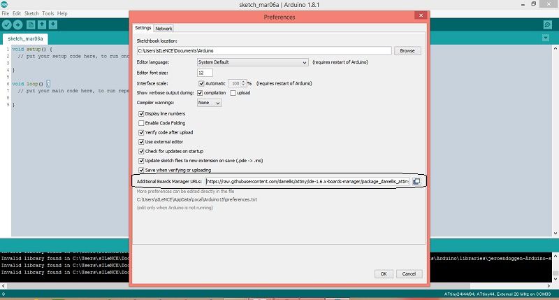
Afte installing Arduino IDE the next step to add additional boards to Arduino IDE. For that we need to Files than References and put this address (https://raw.githubusercontent.com/damellis/attiny/ide-1.6.x-boards-manager/package_damellis_attiny_index.json) to the Additional Board Managar. NOTE: you must have Arduino IDE 1.81 for this step.
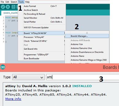
The next step is to add Attiny library. For that we need to go tools -> board -> board manager. Here we need to install the library shown in image given below.
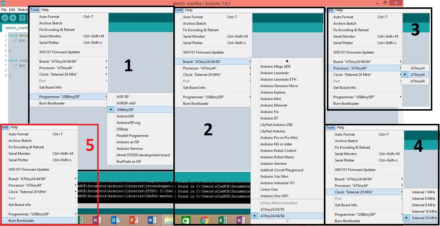
Now Select the device using which you are going to Program, I am going to use my fabISP programmer. The following image shows the steps to select the fabISP programmer and then send the boot loader.
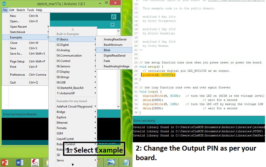
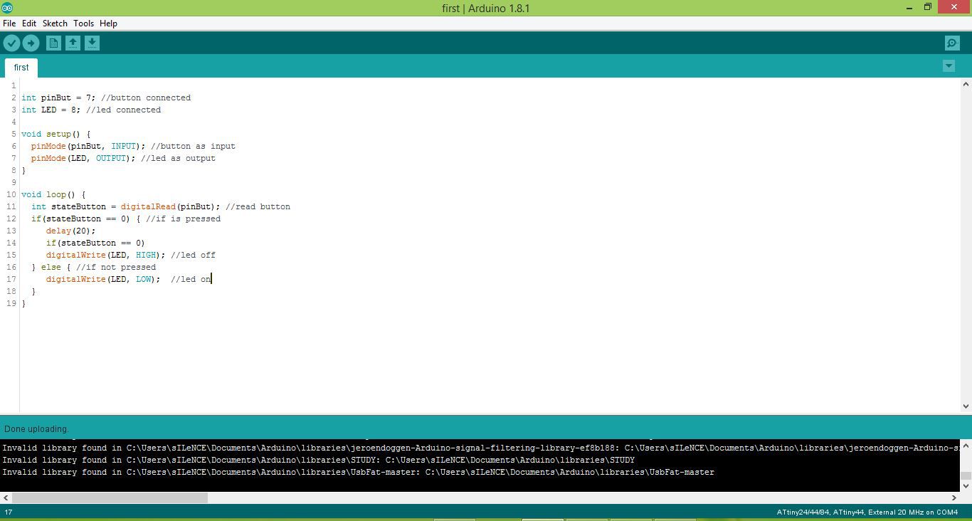
After succesful boot loader its its to test the hello board. Take a simple blank example from arduino and change the pins, in my case LED is connected at pin 8.
Following image show my the program and the changes I made.
Here is the output :)
This is another program that I have written to make the led on and off using button.
Here is the video of the output of above program.
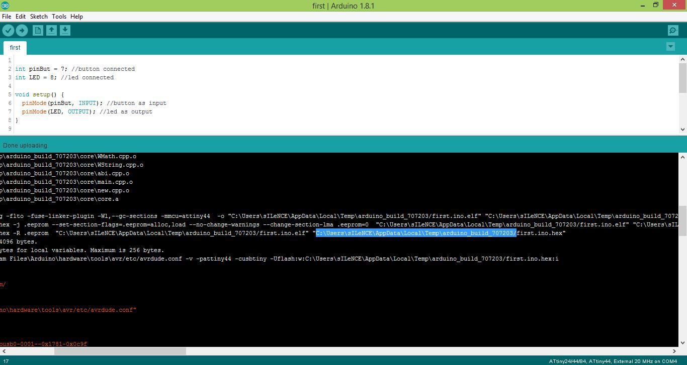
We can also find the hex file location and command for the avrdude of any arduino program after compilation of the program as shown in image below.
2.2 Programming Using C.
2.2.1 Generating Hex file.
I have decided to use Proteus 8 to program my hello board in C becasue this in Proteus 8 we can also simulate our Program as well. I have used this software during my undergraduate degree.
Those how are not familiar with this software, can watch the video given below. Its a really good tutorial for the beginners.
So Now I am planning to program my hello board using my FabISP, For that first we need to download Proteus from HERE and install it, I already have this software so I move to next step directly.
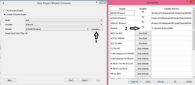
In Proteus the first thing that we need to do in proteus is to create a project, for that I followed the steps shown in figure given below.
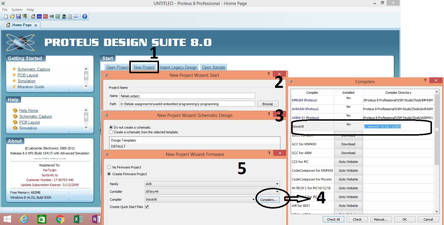
During this process we also need to download the WinAVR compiler as shown in the pervious image. we can download the WinAVR from HERE , and install it.
There is another option in Proteus to download WinAVR compiler. While creating a project we need go to firmware tab and click the compiler, as shown in image given below.
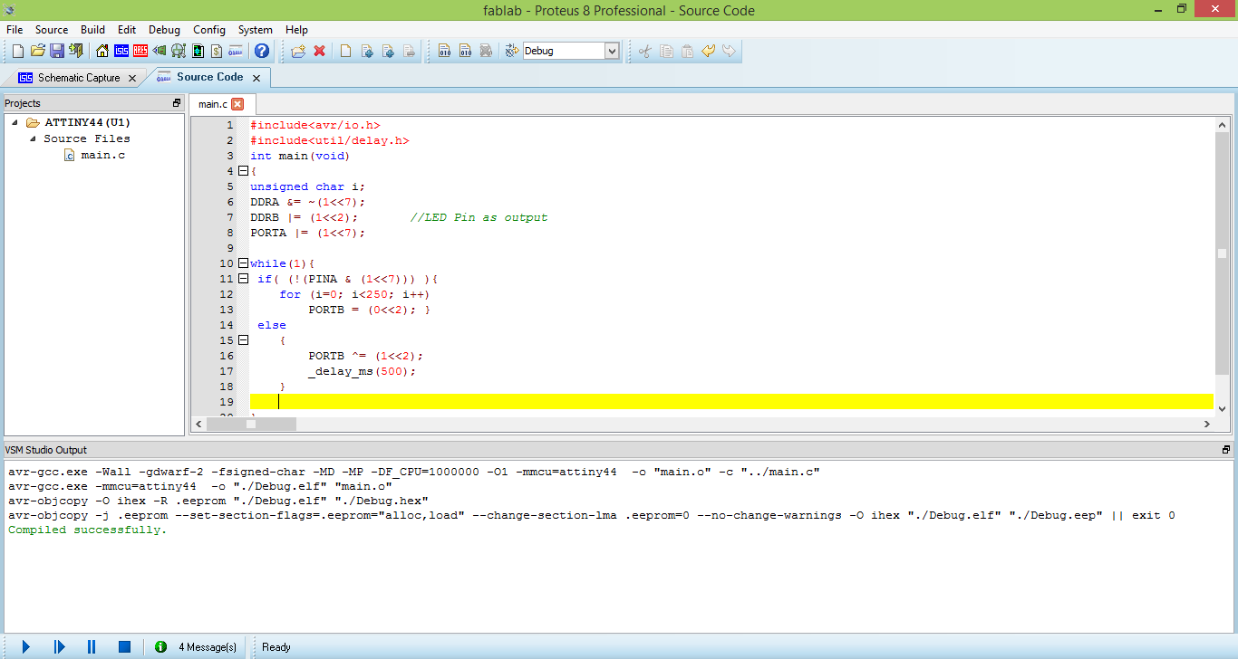
After creating project go to firmware and write your code and compile it. The code I have written for this assignment is shown below.
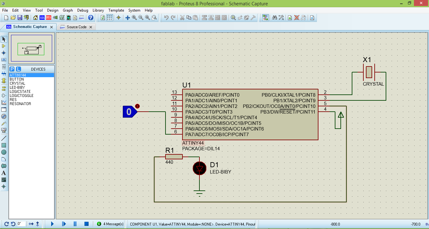
And Here is the schematic to simulate my code.
After compilation we can find our hex file inside debug folder which will be in the project folder, and name the name of file will be "Debug.hex".
2.2.2 Buring hex file using Avrdude.
The First step is to download the Avrdude. you can download it from HERE , and install it.
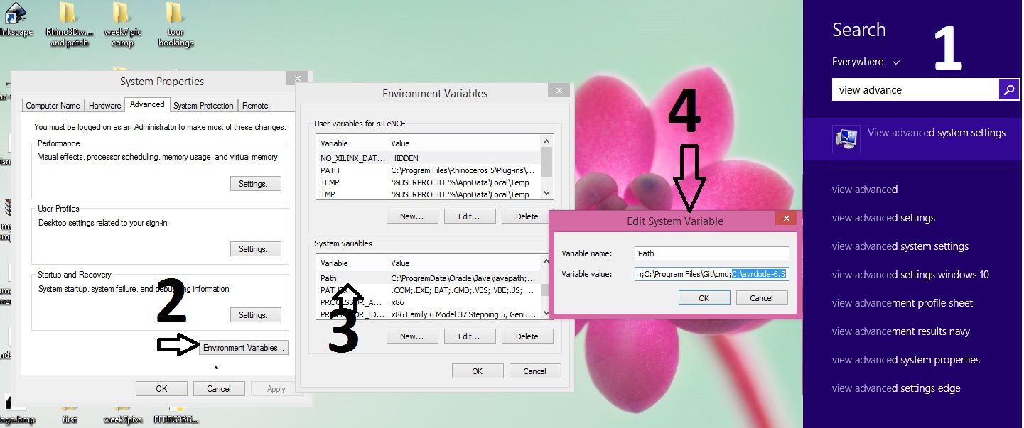
Now to use Avrdude we need to add its path. To do this I followed the steps shown in the image given below.
Now we need to open the command prompt, we can find it by writting "cmd" in search.
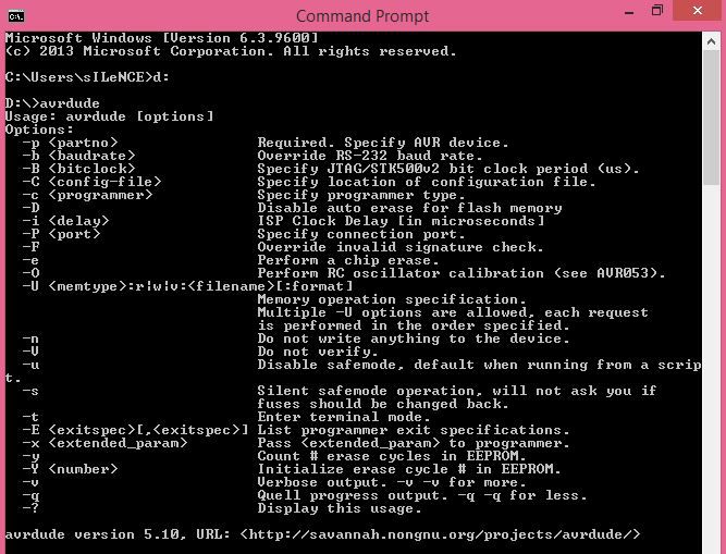
To check the avrdude installed properly we need to type avrdude in command prompt. if you will see the following lines means avrdude is working properly.
The next step is to go to the location of your hex file in CMD my use "cd" command. In my case the location of hex file is "D:\fablab assignments\week8 embedded programming\c programming\ATTINY44\Debug"
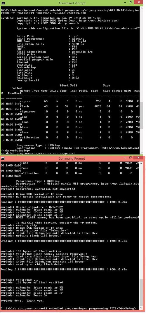
If you are also using FabISP programmer or USBtiny programmer and your board contains ATtiny44 like me, then you can use this (avrdude -v -pattiny44 -cusbtiny -Uflash:w:Debug.hex:i) command to push you hex file to your microcontroller.
if everything is going well you will see the lines in CMD as shown in the snapshot given below.
The Discription of each and every part of the command that I have used for buring hex file in avrdude is given in the manual attached HERE , for me this file become really useful.
Following video shows the output of above program that I have written in Proteus using WinAVR.
Here are other two links which help me a lot.
- http://www.elecrom.com/avrdude-tutorial-burning-hex-files-using-usbasp-and-avrdude/
- https://www.howtogeek.com/118594/how-to-edit-your-system-path-for-easy-command-line-access/

This work is licensed under a Creative Commons Attribution-NonCommercial-ShareAlike 4.0 International License
.