
Assignment
Make something big.1.Idea
After the lecture of Neil I was thinking what should I do for this assignment, as I am from electronic background so for me it is a really good chance to learn new things and to make something usefull. The first thing came into my mind for this assignment was to make a computer table. Because I really need it.:)
I start searching on interent, I founds lots of pictues of tables at google.com but most of them were purpose espacific, I saw a video (given below) from where I got the idea to make this table and finally I makeup my mind and decided to make this multipurpose table, which can be used for Desktop computer, laptop and XBOX.
2. 3D Designing
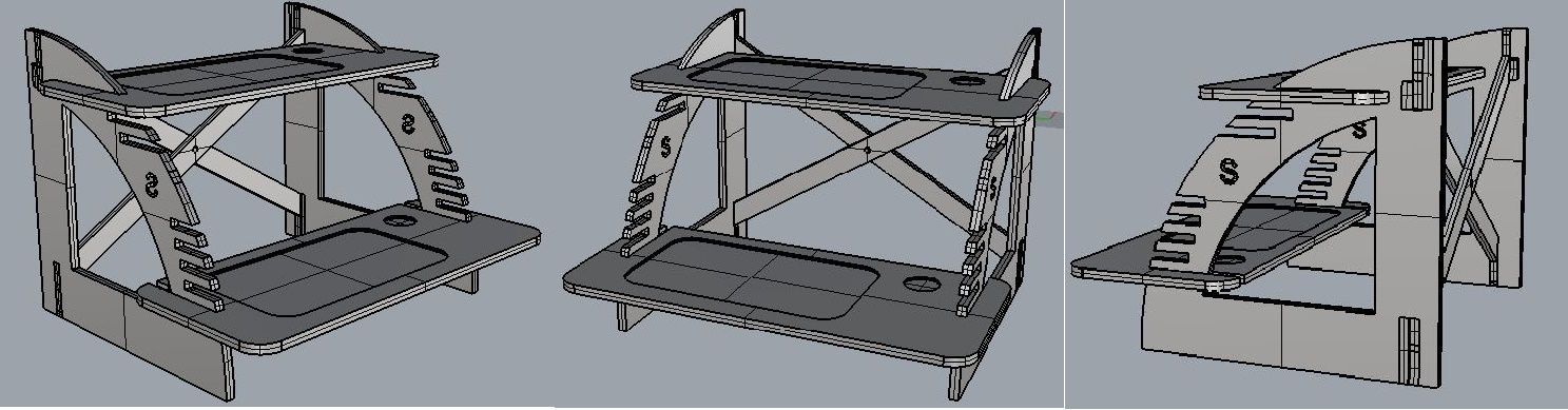
I start working in Rhino 5, because from the experince of previous assignments I found my self working with rhino. so finally I reached at the model shown below.
I Followed the following steps while designing this table.
- 2.1 First thing is to decide the dimension of each component.
- 2.2 Design components one by one in rhino

- 2.3 Assamble the components to get the complete 3D model.
- 2.4 To design the model in rhino, mostly used commands are Boolean Addition and subtraction, rectangle, offset, move, distance, extrudesrf and extrudecuv.
- 2.5 Before milling my model I decided to make an cased model using laser cutting machine. for that I converted my model to 2D my using Make2d command.

- 2.6 After scaling I started cutting my scaled model with laser cutting machine.
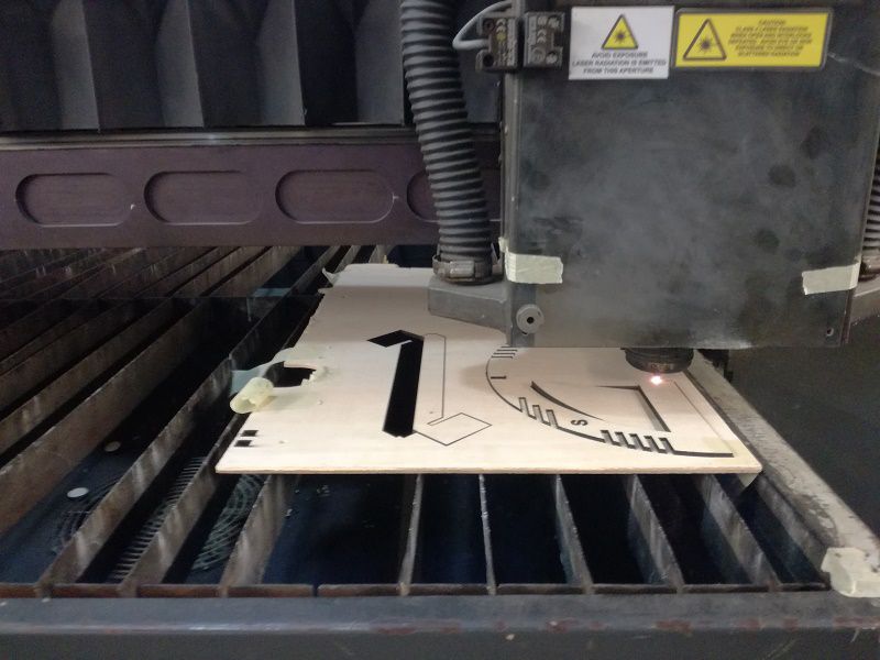
In the first attempt I got the model shown in picture given below.

2.7 In my first small scale leasre cutted model, I found following designing errors and solutions to fix these design errors.
- Model was not horizontally flat. Because of the errors in the length of supports.
- Supports at sizes were not looking good and these supports was not so usefull, thats why I removed them.
- The boards where I we can put our computer/laptop was bit unstable because most part of its length was away from the main body. To counter it I putted joints on these boards.
2.8 After removing the above issues from the model in rhino, I again made its 2D model and nesting for leaser cut my scalled model.
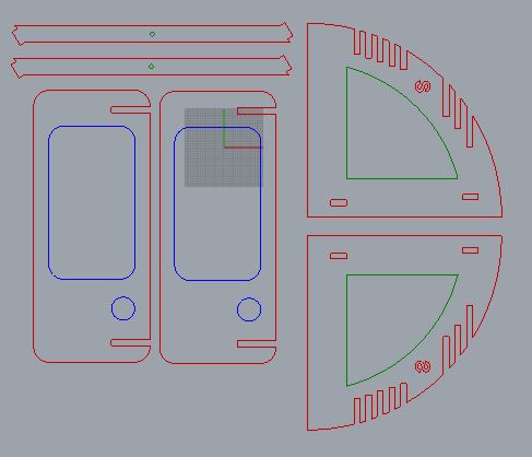
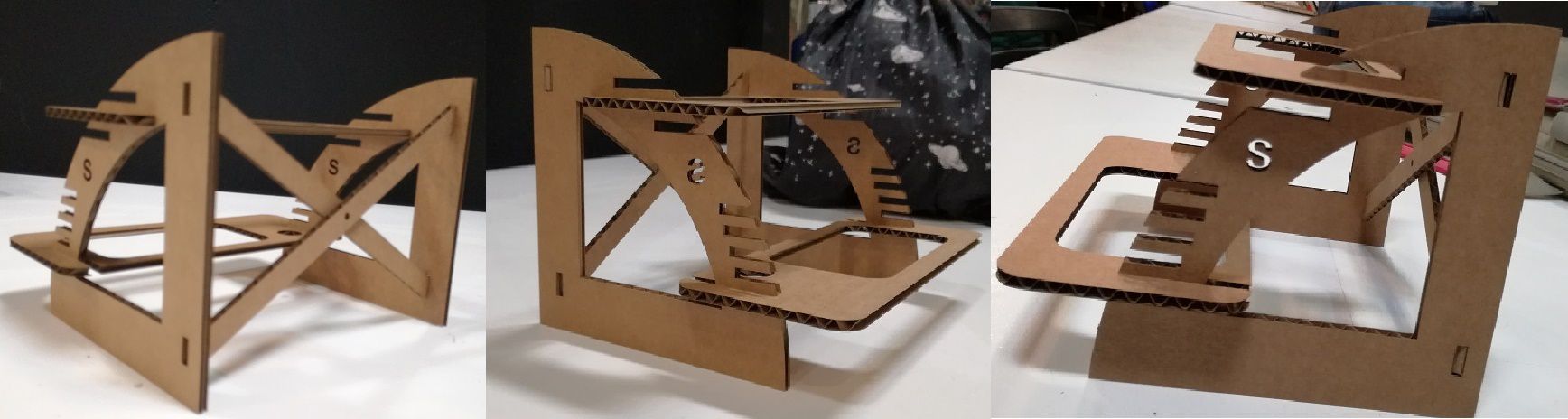
Finally after 2nd leaser print I found everything fine in my model.
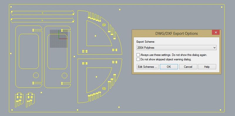
2.9 Export all objects of your model to .dxf format. To export, we need to click on files then export.
3. Generating GCODE
In this part of the assignment I used RhinoCAM. Following are the steps that I did during the process of generating GCODE.
- 3.1 The first thing in RhinoCAM that we need to do is to creat the required layers. we can also create the required layers in Rhino, but in case if you are using anyother software for 3D Design you will have to creating the required layers first.

- In cutinside layer we need to put such objects in which we need holes in inside the larger part of the project. In my case holes in the 2 holes in the each vertical side is included in this layer
- "cutoutside" layer contains the objects that need to be cut from the wood board. Actually it is the outer boundary of each object.
- "dog bones" in this layer we need to put holes where we need to make 90degree curve inside the object, otherwise we night get the inside round edges.
- holes6m and poket5m are the two layers I used for pouketing, I have used two layers because of two different depths, ones is for 5mm and other is for 6mm.
- "Make2D is the layer which we get while exporting our project in dxf format. initially this is the layers which contains all objects."
- "scrws" in this layer screws are added that are required to hold the board on the bed of the CNC machine.
- "Stock" in this layer I have added the plywood boarding with its actual size.
- 3.2 After setting all the layers, we need to set the tool size, In my case im using 6mm flat tool for complete milling. Further details regarding tool are shown in the snapshot given below.

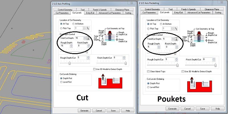
- 3.3 The next important thing is to set the cutting depth and the depth of the poukets. we can set it in respective folder displayed under setup shown in the main window of rhinoCAM. Further setting can be seen in the image given below.
- 3.4 Further details and setting regarding setting that I have done in RhinoCAM can be found in the video given below, that I have uploaded on youtube.com.
- 3.5 The last part is to see the simulation of the complete operation of CNC machine. The video below shows the simulation of the operation.
4. Milling
For milling I am using Praxis CNC machine, because I got my turn when only this machine was free.
Following are the steps for milling.
- 4.1 The first thing before start milling that we need to do is to clean the bed of machine, otherwise we will get the uneven z-axis.
- 4.2 Now its turn to fix the tool in machine, In my case I am using 6mm flat tool.
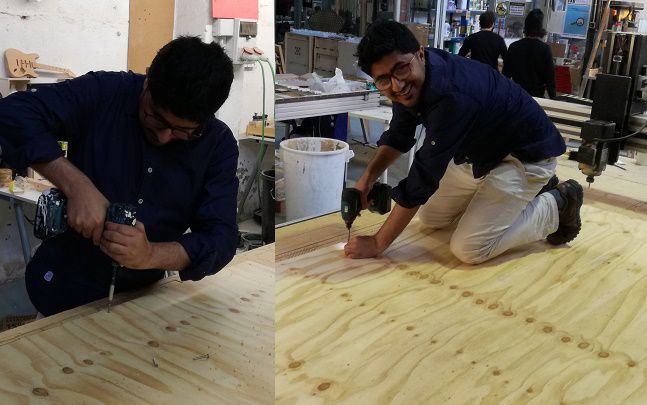
- 4.3 Open the software (Mach3control) and set the origion XYZ by using the botton shown in picture given below, make sure the origion must be at the mid of the thinkness of tool.
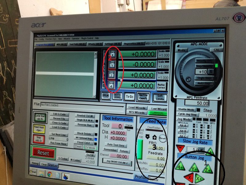
1 is showing the buttons to adjust the axis, 2 shows to set the origin and 3 shows the control for slinder which actually rotate the tool.
- 4.4 Send the GCODE file to machine to drill the screws.
- 4.5 Send the test GCODE file and mill it.

After milling the test part I came to know that I need to increase the size of holes for supports in the model, initially the tolerance was 0.2mm then I made the tolerance of 0.44mm.
- 4.6 Now the final step for milling is to send the GCODE of your model.
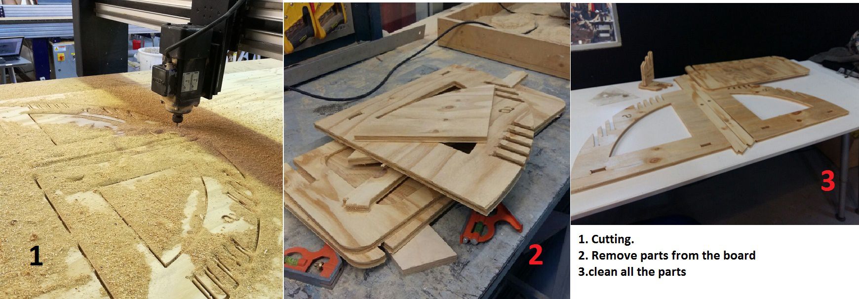
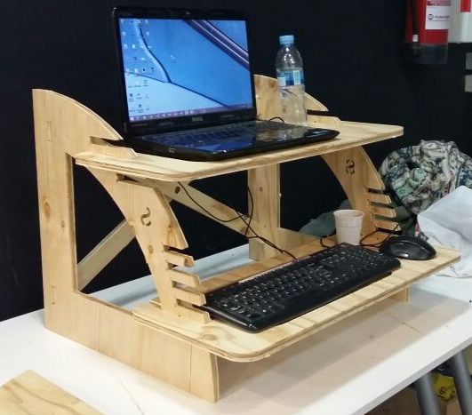
- 4.7 Final part is assembling the model. By following the steps shown in the picture shown below we can assemble the model easily.
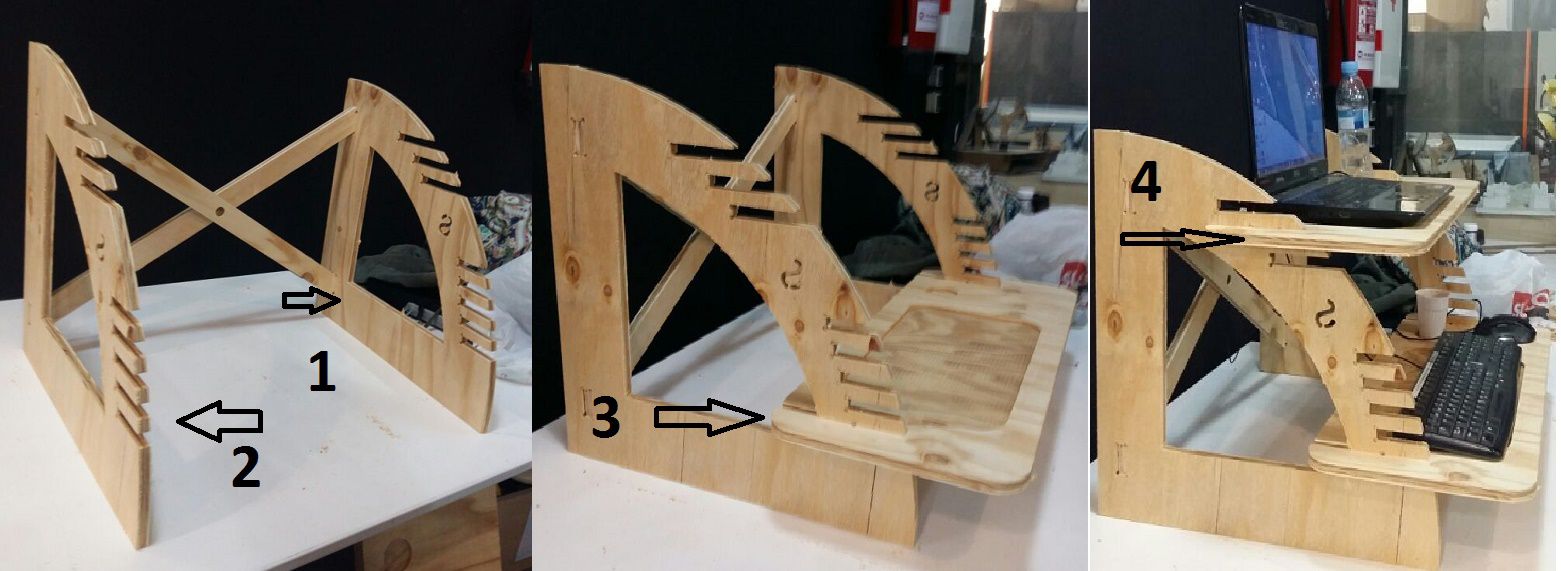
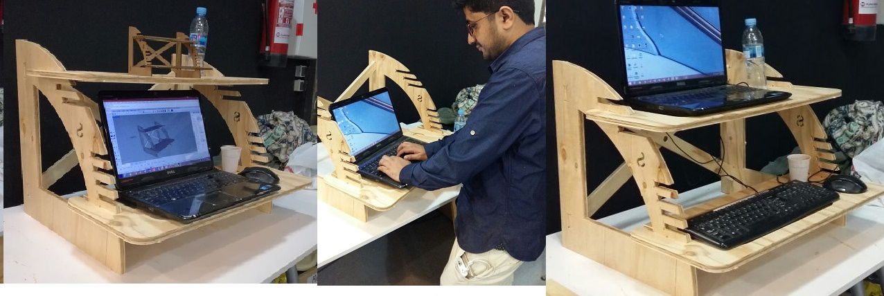
Here is my project ready, we can use it while standing, setting for using laptop, desktop computer or Xbox.
Download All file of this week Here

This work is licensed under a Creative Commons Attribution-NonCommercial-ShareAlike 4.0 International License
.