
Assignment
- Add an output device to a microcontroller board you've designed and program it to do something.
0. Idea.
For this assignment I decided to interface E-ink diplay with the microcontroller board. Because of many reasons I decided to work with E-ink diplay. The first think is that it really fascinate me due to its ability to retain its display will power is disconnected, its viewing angle, power consumption and capability of reviewing contents even in sunlight. So these are the reasons I decided to work with it.
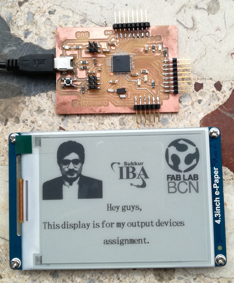
And Here is the output.
1. E-ink Display.
I was looking for display which can be interfaced with attiny44 or anyother avr microcontroller. After searching a lot on google, I decided to order Waveshare 4.3 epd display module from here .
The advantage of this e-paper diplay module is that we can find its arduino library form here and it is also support Serial communication with microcontroller. so though for this assignment this display module is very suitable.
2.Selection of microcontroller
Initially I thought to interface the display module with hello world board with attiny44 that I have designed in week 6. After putting my 2 to 3 days I was not able to interface the display with attiny44 because of the following reasons
-
After Adding the library of E-paper display module to the arduino, I started with example of this library. The first problem I faced was the following errors.

This was because there is no any hardware UART or USART module in attiny44. we can fix this error by creating virtual serial port on the any two pins of attiny44 by using the SoftwareSerial.h library which can be easily downloaded from github.com. But this also increase till bit complexity as I need make the changes in complete library of the display module.
- The next problem was the requirement of the dynamic memory of the microcontroller. Initially the default example of the module was occuping 92% of program memory and 255% of SRAM. Now to overcome this problem we need to remove arrays that the library and the program it self is using, but this will limit the possiblity and the function and shapes I want to display on the display. Even after reducing the arrays from the program I was in need of 7144 bytes of program memory and 966 btyes of SRAM. which is not available in attiny24/44/84.
- There was another solution of second problem is to store all varaibles in EEPROM, but again this will cause further complexity, and make it difficult to use the system (attiny24/44/45 + e-paper display module) for anyother application like interfacing input devices and wifi or bluetooth.
So, Because of all reasons I decided to designed another board with either ATMEGA328p or ATMEGA32u4 because these two microcontroller will provide me enough SRAM to interface e-paper module.
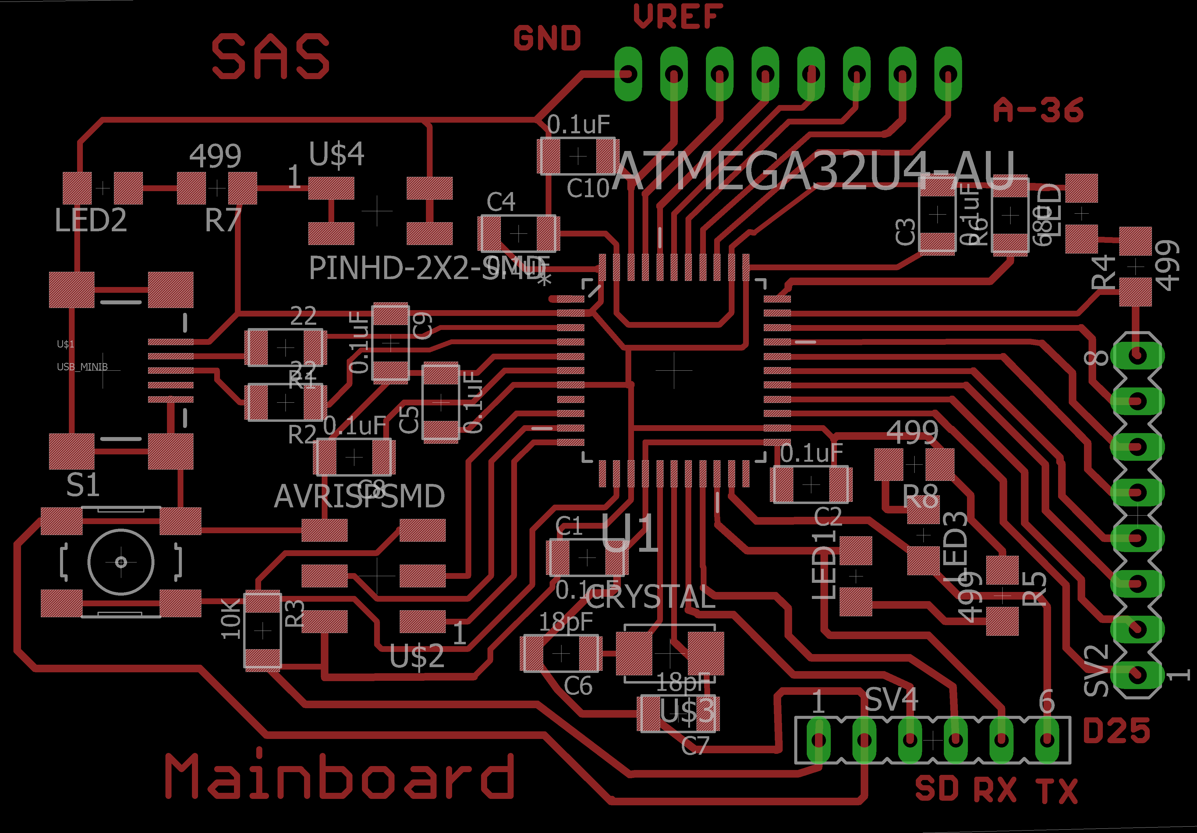
3. Mainboard Development.
Now the next task is to develop and mainboard with ATMEGA328p or ATMEGA32u4. I decided to go with ATMEGA32u4 becasue it is more powerfull then ATMEGA32u4 in term of memory and interfaces, it also have USB interface which help to program it without any external FTDI cable or programmer.
There are lots of generic boards of ATMEGA32u4 on internet, but I was looking for a board with single layer PCB and which can be developed in our lab, so I started with FABLEO, which can be found here
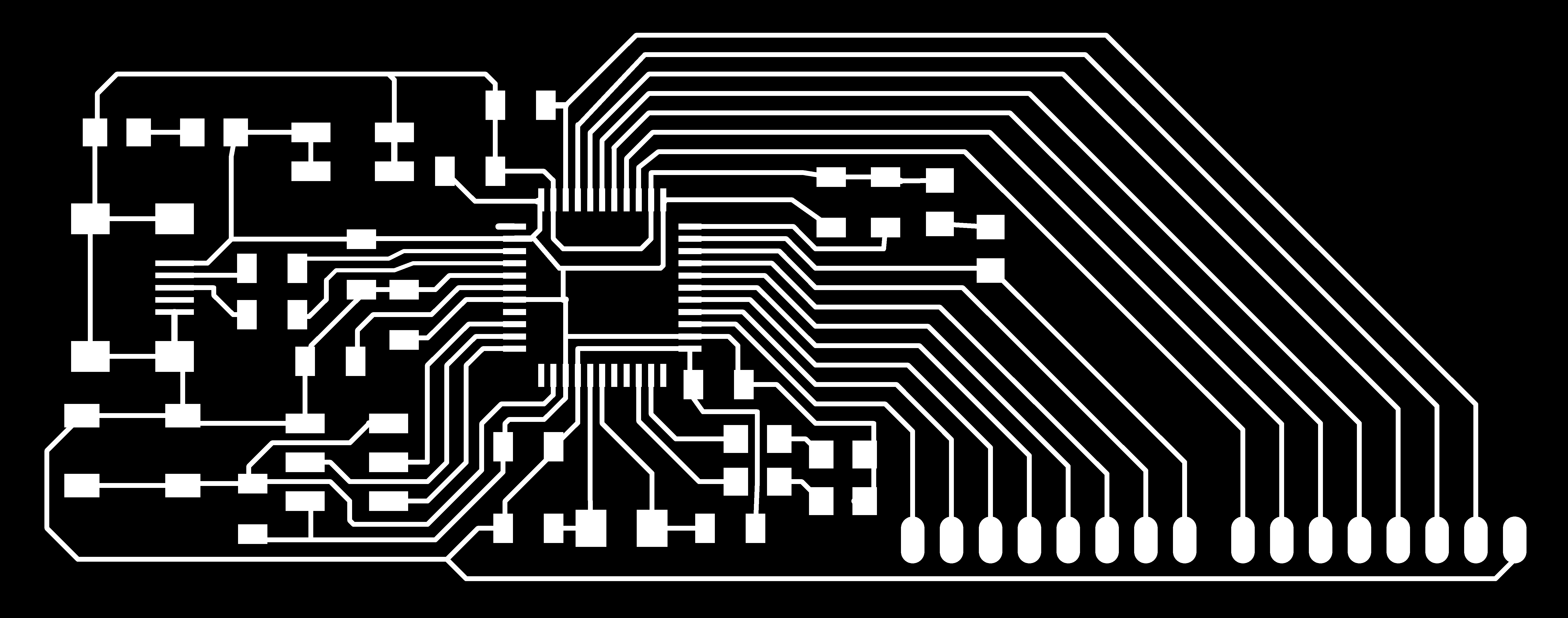
I rearranged the board to make it smaller and made some changes (takeout pins for serial communication and I2C) and made it as per my requirements. This was not an easy take to take out track and do manual routing, but finally I managed.
After desiging board, the next task is to create the rml files from fabmodule.org and mill the board using Rolland SRM-20 machine. We can find more details of this step in week 4, but one think to remember is that we can not mill the fableo board with 1/64 tool size, we need to use 0.254mm tool to mill this board. Few images of this process are given below.
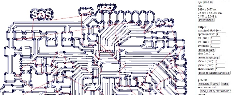
I mill the board straight with 0.01 inche tool size, and the following image shows the result after milling.
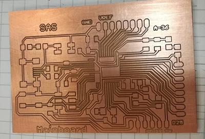
Apparently board looks good, but it yes really difficult to solder it. Because of very small clearance, soldering the conponents on the board becomes really difficult. I realised that most of the copper on board was short with one another. After spending a long time in debuging I decided to remill the board.
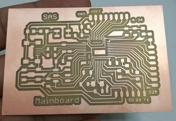
I will suggest to those who wants to mill such boards, mill the board with 1/64 tool and then mill the board again with 0.01 tool, otherwise you will waste your time and energy while soldering the board. Milling the same board twice with 1/64 and then 0.01 tool will give you excellent results and soldering with become comparatively easy.
While milling the board second time I first used the 1/64 tool and then 0.01 tool and the results were awesome.
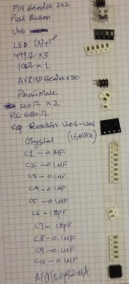
Now it is turn to solder the components again on the new board. Following image shows the list of components required.
After soldering and debuging the board its time to program it.
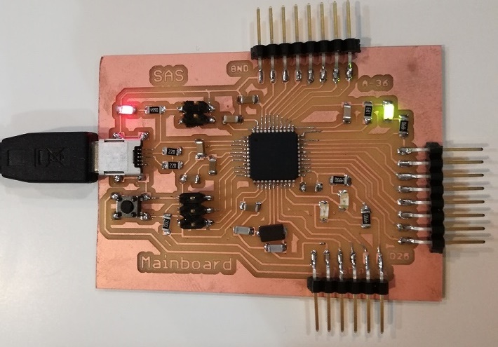
I programmed the board using Arduino IDE. Simply connect the board with your PC using USB cable, the operating system of PC will install some drivers of ATMEGA32u4. After that open Arduino IDE and select the board Arduino Leonardo becasue Leonardo board contains ATMEGA32u4, and then upload the board loader. It will take your seconds and then try to burn blink example. If every thing goes well you will see the board as shown in picture given below.
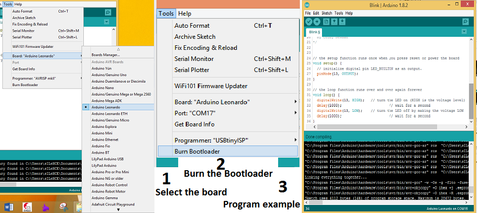
If every thing goes well you will see the board as shown in picture given below.
4. Interfacing E-paper Display.
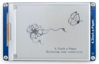
This E-paper Display (EPD) can be interfaced with PC as well, as its supports Serial Communication that is why we can connect it with PC using FTDI cable. It is alway good to connect the EPD with PC first and send check that display is working or not. I tried to up the EPD with microcontroller without checking on PC and wasted full day trying to make it work then I realised after connecting the display with PC that EPD is not working properly. This is how it looks like when I connected the power.
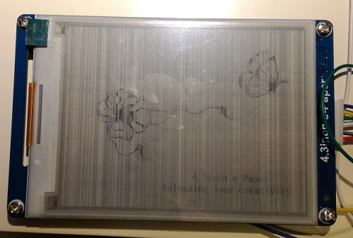
EPD alway refresh on every reset. If your display in not refresh on power up, it means EPD is not working properly. I ordered another from amazon.com
4.1 Connecting E-paper Display module with PC.
This Waveshare EPD module has its own software for connecting it with PC, can be downloaded from here
This (http://www.waveshare.com/wiki/4.3inch_e-Paper) is the really good tutorial I used to interface this module.
Following table shows the wire connections of EPD with FTDI cable for connection with PC.
| FTDI Pins | 4.3inch e-paper wires |
|---|---|
This (http://www.waveshare.com/wiki/4.3inch_e-Paper) tutorial shows the step by step guide to connect and check the epd using PC.
I followed the steps given in the above tutorial and found EPD completely fine.
4.1 Connecting E-paper Display module with microcontroller board.
Now this is the main task to interface EPD with microcontroller board. For that the first thing we need to do is to make connections as given in table below.
| Mainboard Pins | 4.3inch e-paper wires |
|---|---|
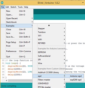
The next thing to Program the board, for that it is better to test the demo first. After adding the library of EPD module then you can find the Demo program in Examples. As shown in figure given below.
Before uploading the program following please remember to do the following things.
- As the Demo program is for arduino uno (Atmega328p) and I am using ATMEGA32U4 so we need to changes the pins as given in table above in this section.
- Simply changing the pins will not work, because there are two serial ports in ATMEGA32u4. We need to make some changes in library of EPD that we have added. For that go to next step
- Find the Arduino library folder in your computer, in my PC it is there (C:\Users\Sohail\Documents\Arduino\libraries\LibraryEPD-master).
- Now here we need to find the file "epd.cpp". If you are unable to find file location simply search the file in your C: drive.
- Open the file in notepad or notepad++ or in anyother relavent software and Search for "Serial" and replace it by "Serial1", because in ATMEGA32U4 the default serial port is used for communication with the Arduino IDE. We need to use another port to communicate with EPD module
- You can also download updated library for this EPD module that will work on Leonardo or this main board at the end of this page.
- Now save the file and upload the demo example sketch.
After following all above steps you will be able see the output on your EPD as shown in the video given below
Now I need to write my program to show some different images and text.
Text is pretty straightforward, we can use the function "epd_disp_string("text here", X, Y)" and we can use "epd_set_en_font(ASCII32)" for fonts size. so far we this module has three fonts size by default in its Memory, that is ASCII32, ASCII48 and ASCII64.
To display images we need to follow the following steps.
- Make sure the resolution of the image is less than 800x600 pixels. Start the tool mspaint.exe on Windows to open the image to be converted;
- Select the option 24-bit bitmap in the Save as Type list, to save the image as a bmp format file
- Start the software tool provided by Waveshare: uC-GUI-BitmapConvert.exe
- Click File -> Open, and select the bitmap image you want to convert
- Click Image -> Convert Into -> Gray4 (2 BPP);
- Click File ->Save As, and select the option Windows Bitmap file(*.bmp) in the Save as Type list, and then enter a correct file name and save the image.
- Conditions for correct file name: The name of the image should be in uppercase English character(s) with the length less than 10 characters (the symbol “.” is included). And the string length of the image name should be less than 11 characters, in which the ending “0” is included.
- Store that image in microSD card and put this microSD card into the module.
- microSD card must be FAT32 format.
- Do the same with all the image file you want to show on the EPD module.
After following the all above steps you can use the function "epd_disp_bitmap("file_name", X, Y)" in your program to display the image.
For further details of function and commands please go through the tutorial of EPD module attached at the end of the page.
After following the all above steps here is my final output. :)
So finally after milling and soldering the mainboard twice and burning my first EPD module, this week becomes most expansive, tough and tiring week so far.
Download All file of this week Here (including Arduino files, Eagle files, tutorial, library for EPD module, BMP image conversion software and software to connect EPD with PC)

This work is licensed under a Creative Commons Attribution-NonCommercial-ShareAlike 4.0 International License
.