
Assignment
- Automate your machine.
0. Introduction.
Our Group project is to make 3D printer and we are working on Wally 3D printer. This week I am responsible for Programming of Wally 3D printer.
Assembly of a 3D printer is a massive task due to the ultraprecise nature. We had an idea that designing and setting up the hardware will be easy but caliberating software and hardware would be nothing less than challenging. So we just took a big leap of faith thinking that if nothing else we will get a thorough experience.
1. Hardware / Software platforms
over the past few years numerous hardware/software platforms have appearead for 3d printing. Here we present a brief of the most common hardware / software platforms.
Replicating Rapid prototyper (RepRap) project was founded about a decade ago and this project has evolved massively with world wide interest of enthausiasts. Over time this platform has matured into very stable (feature rich) 3D printers which cost less than 500 USD. In market there exist several varients of freely available software and hardware.
Since support for Marlin is widely available in our fablab therefore there was no discussion for the choice of firmware. There were acouple of RAMPS 1.4 boards available in the 3D printer room and we were lucky enough to borrow them there was no discussion on the choice of hardware either.
Marlin is firmware for RepRap single-processor electronics, supporting RAMPS, RAMBo, Ultimaker, BQ, and several other Arduino-based 3D printers. It supports printing over USB or from SD cards with folders, and uses lookahead trajectory planning. Marlin is licensed under the GNU GPL v3 or later. It is based on Sprinter firmware, licensed under GPL v2 or later.
RepRap Arduino Mega Pololu Shield, or RAMPS for short. It is designed to fit the entire electronics needed for a RepRap in one small package for low cost. RAMPS interfaces directly onto an Arduino Mega with the powerful Arduino MEGA platform and has plenty room for expansion. The modular design includes plug in stepper drivers and extruder control electronics on an Arduino MEGA shield for easy service, part replacement, upgradability and expansion. Additionally, a number of Arduino expansion boards can be added to the system as long as the main RAMPS board is kept to the top of the stack. The useful user manual for RAMPS is available here .
2. Bill of materials
The bill of materials of electronic components necessary for the Wally project is listed here .
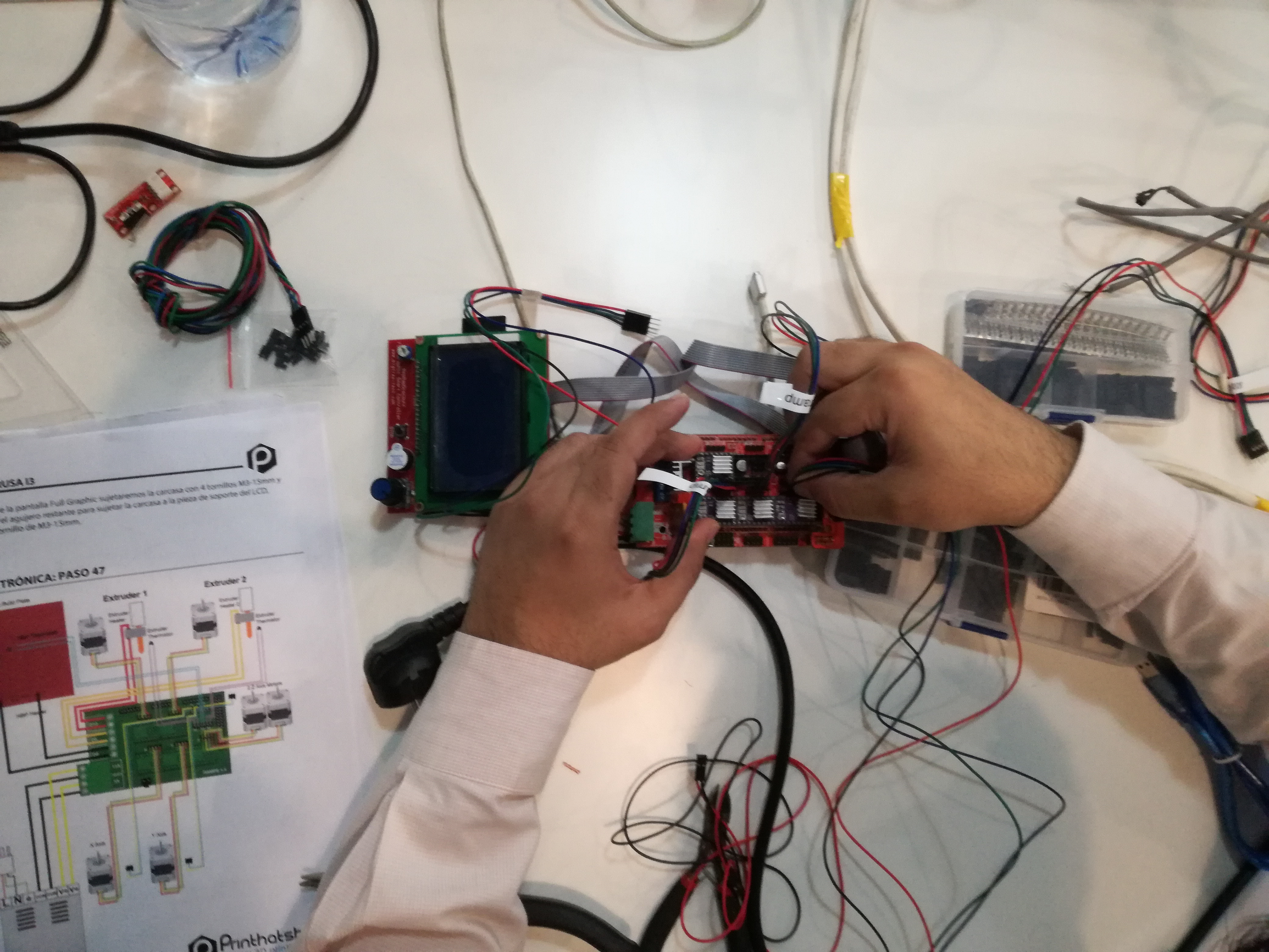
3. Electrical Assembly

We started putting together the power supply, stepper motor and interconnection with RAMPs hardware. A good user manual is avaliable at reprap website . After double checking all connections we powered up the circuit.
4. Marlin firmware
It is a well known firmware used for many single processer based 3d printer. It is really popular because of its flexebilty, we use this firmware for almost any 3D printer with some changes in configuration.h header file. It is easy to use because we can find lots of discussion forms regarding discussing its problems and solutions, and the best thing is that it is Arduino Based and open source.
To understand the marlin firmware I found the video shown below very useful.
But the problem is that we have very limited stuff on the internet to use this firmware for wally 3D printer. As we have only few success cases of wally 3D printer.
As the printing mechanism of wally is not straightfarword, It start printing from top to button like Ultimaker printers and z-axis moves in curve instead of straight.
Now the next step is to configure the marlin firmware
4.2 Configuration of marlin firmware
The first step is to download the updated marlin firmware from HERE
Now open the folder and find marlin.ino file and open it in Arduino IDE.
You will see lots tabs opened in Arduino IDE, as shown in picture given below.
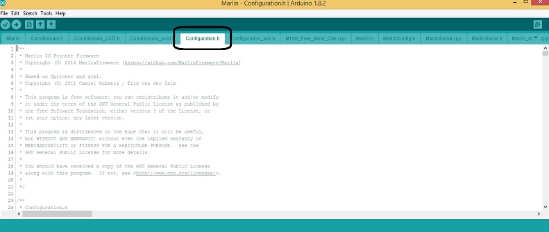
Find the configuration.h file there.
Here we need to follow the comments and uncomment the files of hardware we are using. In our case we made following changes in configuration.h file to configure the firmware for our printer.
- #define BAUDRATE 115200
- #define TEMP_SENSOR_BED 0
- #define X_MIN_ENDSTOP_INVERTING true // set to true to invert the logic of the endstop.
- #define Y_MIN_ENDSTOP_INVERTING true // set to true to invert the logic of the endstop.
- #define Z_MIN_ENDSTOP_INVERTING true // set to true to invert the logic of the endstop.
- #define DEFAULT_AXIS_STEPS_PER_UNIT { 80, 80, 400, 200 }
- #define DISABLE_X false
- #define DISABLE_Y false
- #define DISABLE_Z false
- #define INVERT_X_DIR false
- #define INVERT_Y_DIR true
- #define INVERT_Z_DIR false
- #define X_MIN_POS 0
- #define Y_MIN_POS 0
- #define Z_MIN_POS 0
- #define X_MAX_POS 275
- #define Y_MAX_POS 275
- #define Z_MAX_POS 155
- #define SDSUPPORT
- #define REPRAP_DISCOUNT_FULL_GRAPHIC_SMART_CONTROLLER
- #define DEFAULT_NOMINAL_FILAMENT_DIA 3.00 //Enter the diameter (in mm) of the filament generally used (3.0 mm or 1.75 mm) - this is then used in the slicer software. Used for sensor reading validation
Our modified configuration file is available HERE .
5. XYZ, Extruder and Endstop Caliberation
Once all the cables were connected we were in a position to powerup the circuit. The next and most important thing was to caliberate the system. Using default feeds and speeds values from firmware or taking values from any internet directly would not work and we had determine them through simple calculations, trial and error.
- For x, y movement we fixed 80 steps/mm this is the default value, the modifications were made in the preprocessor.
- For vertical movement z was altered in a way that total travel length is equal to 15 cm. This was also calculated through trial and error.
- For extruder, we started with the default value i.e. 500 steps/mm in the firmware and tried to extrude the filament of 5 cm, when we uploaded this program the printer extruded 12 cm. So we concluded that extruder steps/mm should be 200. Now with this adjustment we extruded 2cm of the filament and we got the same.
- To determine the maximum coverage of X and Y we used simple calculations. As the stepper motors move 1.8 degrees in one step, so for 360 degrees it will take 200 steps. In the case of wally we can move its arms moves until it makes 90 degrees between the first and second part of that arm, this is also true for Y axis movement as well, so this region is the area where we can move X and Y. We could validate the maximum range of wally using repiter host by through command "M92 X200 Y200 F300". And M500 to save the values.
- Initially the motors were not moving in the reverse direction, we changed the polarity of motor connector but to no avail. Then we made the following changes in firmware which solved the problem.
#define INVERT_X_DIR false
#define INVERT_Y_DIR true
#define INVERT_Z_DIR false
#define DISABLE_X false
#define DISABLE_Y false
#define DISABLE_Z false
6. Octoprint:
We found very good youtube tutorial given below.
6.1 The list of stuff required for octoprinter.
- Raspberry Pi
- 8G SD Card
- 1A 5V DC power supply
- USB Cable
- Ethernet cable (Easily Wifi-able)
- Webcam (optional)
- PuTTY
- Octopi 0.13
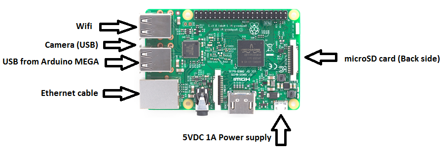
6.2 Connections
6.3 The step by step procedure to setup octaprint server are as follows
- Download the image file for Octopi 0.13 from here , unzip it and install.
- Insert your SD Card into the computer and format it.
- Download the Win32DiskImager-0.9.5-install.exe , and run the program for install the program.
- Run Win32DiskImager.exe
- Select your SD Card drive letter in Device droplist.
- Select the image file that you download from Octoprint. e.g. 2014-06-20-wheezy-octopi-0.9.0.img
- Click 'Write'
- When the image is successfully written, Do not remove It from the PC.
- Open the SD card drive and find the file octopi-network.txt and open it.
- In "octopi-network.txt" you will find comments, following them and configure it with your internet connection.
- Now remove the SD card from computer and plug it into the Raspberry pi.
- Now make the connections and connect power supply, Ethernet cable or Wi-Fi and Arduino mega with raspberry pi as shown in figure given above.
- Power On the raspberry pi now. And access it from your browser by writing http://octopi.local
-
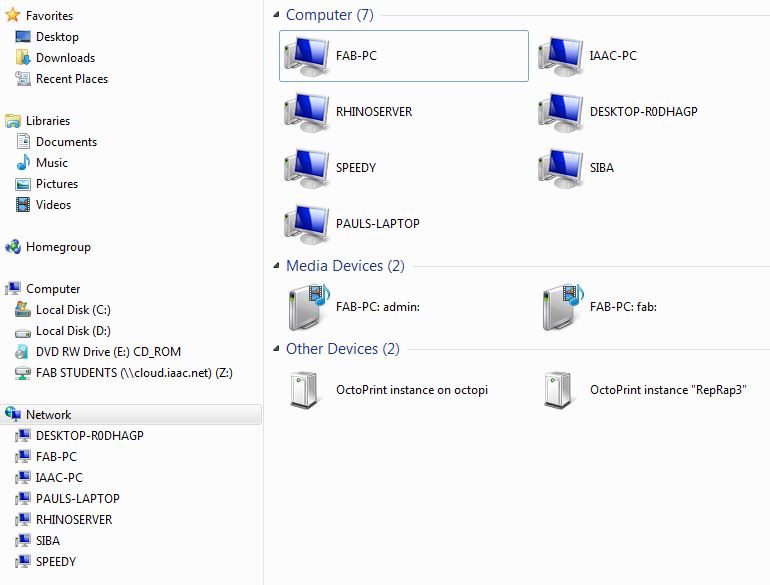
You can also access the octopi server from "Networks" Option in My PC of your operating system.
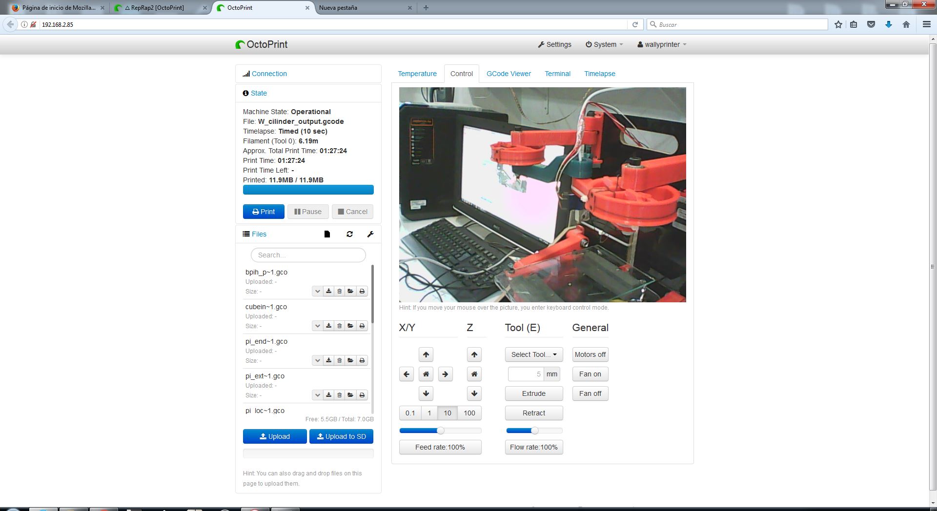
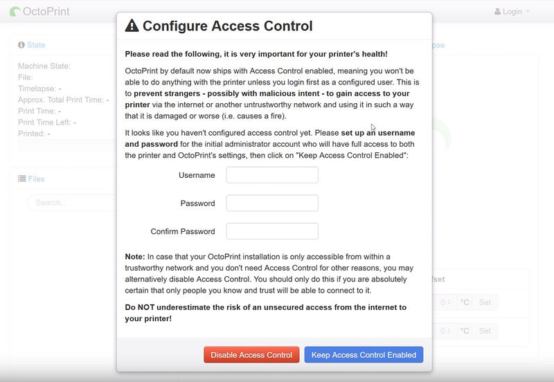
- After opening the webpage of octoprint, the first thing to do is to set the username and Passward.
- The last step is to log in to the octoprint webpage and click on the connect button to make connection with the printer. You can set any baud rate from the group of given baud rate. We are using 115200. Octo printer is ready now, just drag and drop your gcode file and hit print to start.
7. Suggestions for further improvement
Wally has been a very rapid project. Although its more of assembly and caliberation based project. This project has been a wonderful opportunity for us to learn variety of things related to machines that make machines.
- The output quality of system could be improved through further fine tuning of the system parameters.
- The printing tray is not perfectly flat and this problem surfaces.
8. Final working video of wally .
Document the complete project is given below.
Download All related file of this project from Here

This work is licensed under a Creative Commons Attribution-NonCommercial-ShareAlike 4.0 International License
.