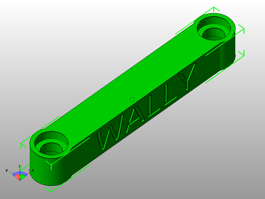
Fully Funcitional Wally

Wally Project
Wally Timelapse
So for this week is concerned, its all about Group Asssignment to develop a machine that makes (the machine). It was quite a new experience for all of us to work together in a group to develop something. Initially we planned some meetings to come up with an idea of a machine that we can make. Finally after some due delibration we decided to make a special type of 3D Printer generally called "Wally".
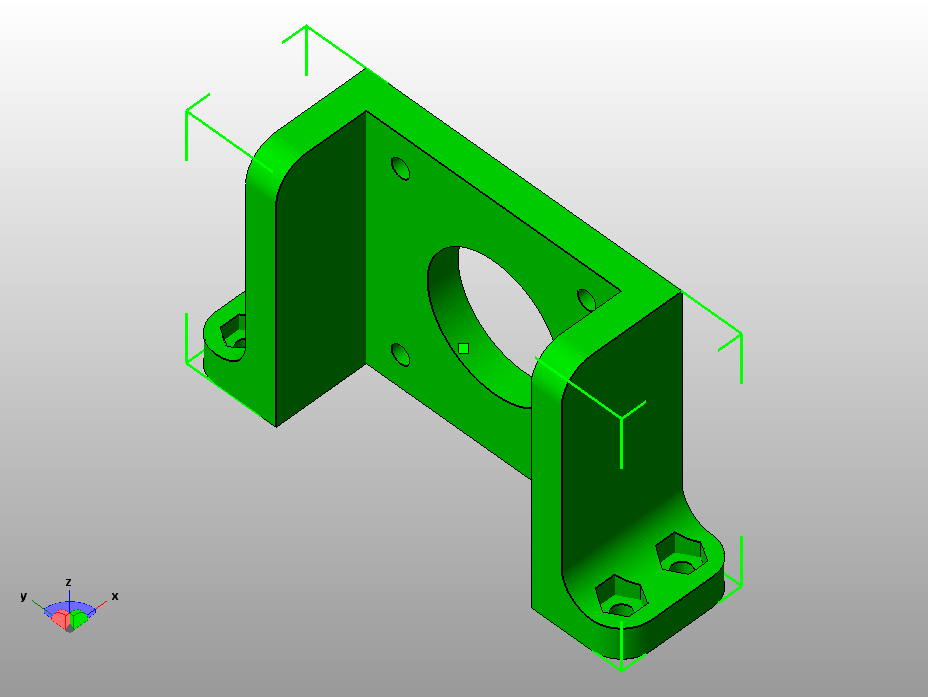
Wally is a wall bot where everything is mounted on the wall. Wally is a variant of reprap 3D printers which belong to Selective Compliance Assembly Robot Arm (SCARA) family. The idea was to make Wally as simple and low cost as possible, and use much less plastic and bearing than other does, but has faster speed and better resolution.
The printed parts take almost 1kg of PLA and 40-45 hours to print a complete set. Nicholas Seward recommends PLA printed at a 0.3mm layer height and 15% infill with 3 perimeters.
RepRap Community is working for the portable and replicable 3D printers. RepRap is humanity's first general-purpose self-replicating manufacturing machine. Since many parts of RepRap are made from plastic and RepRap prints those parts, RepRap self-replicates by making a kit of itself - a kit that anyone can assemble given time and materials.
Wally - The Ultimate Printer
Wally works on inverse kinematics, In robotics, inverse kinematics makes use of the kinematics equations to determine the joint parameters that provide a desired position for each of the robot's end-effectors. Specification of the movement of a robot so that its end-effectors achieve the desired tasks is known as motion planning.
Wally - Inverse Kinematics
Once the idea was ready, now its time to divide the task and get started for mechanical design.
Well there is quite a bit of help available for this designing this printer, first of all we made a list of the components and materials we will need during the process of making the printer.
We started our work, first one was Fida, his task was to cut and assemble frame so that we can further proceed.
3D Model of the Frame
Once the frame was ready now it was the time of print the XY and Z axis components their assembly.
XY Axis Working of Scara
Wally places the stepper motors on the walls of the frame to reduce the wieght and allow the arm to move at faster speeds. The position of the arms is adjustable through fishing line drive belt as illustrated below
XY - Axis Working
Design of Wally is a sizeable task. For the mechanical design assignment I and Nisar are jointly responsible for working on the XY- axis movement framework.
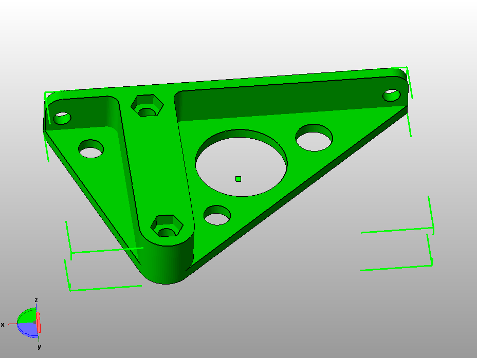
The mechanical assembly of XYh movement axis required the following components
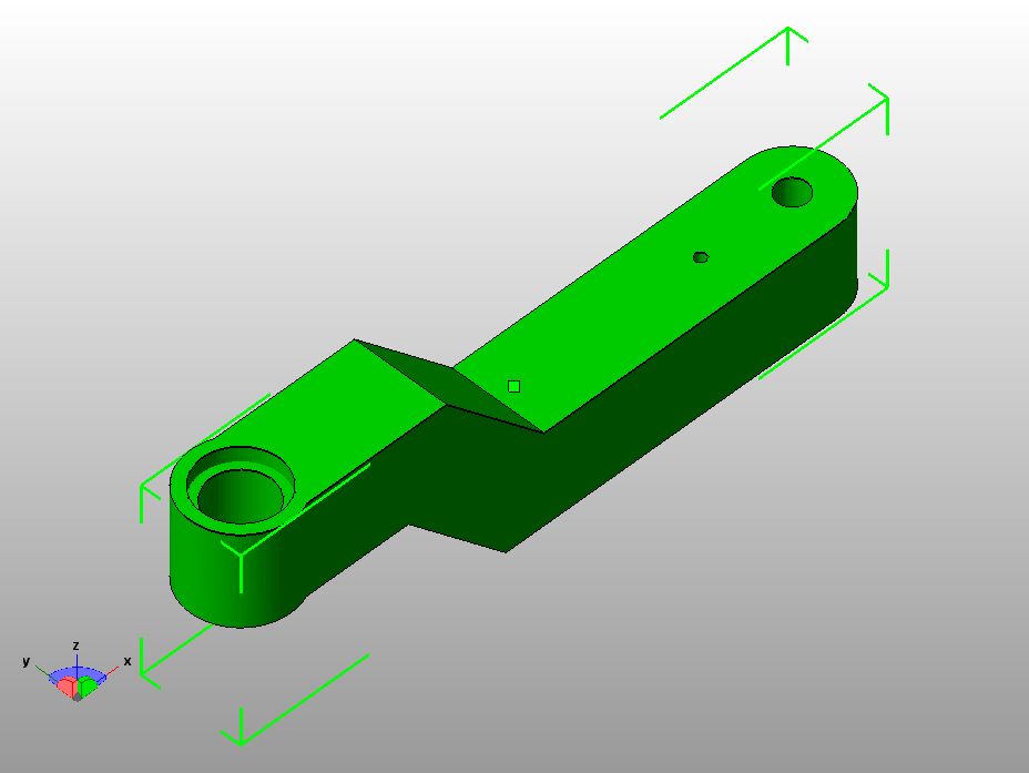
xy forearm.stl, Qty: 1
xy mount.stl, Qty: 2
xy pulley.stl, Qty: 2
xy ubis mount arm.stl, Qty: 1
xy wall arm.stl, Qty: 6
xy arm wall bracket.stl, Qty: 2
big pulley.stl, Qty: 2
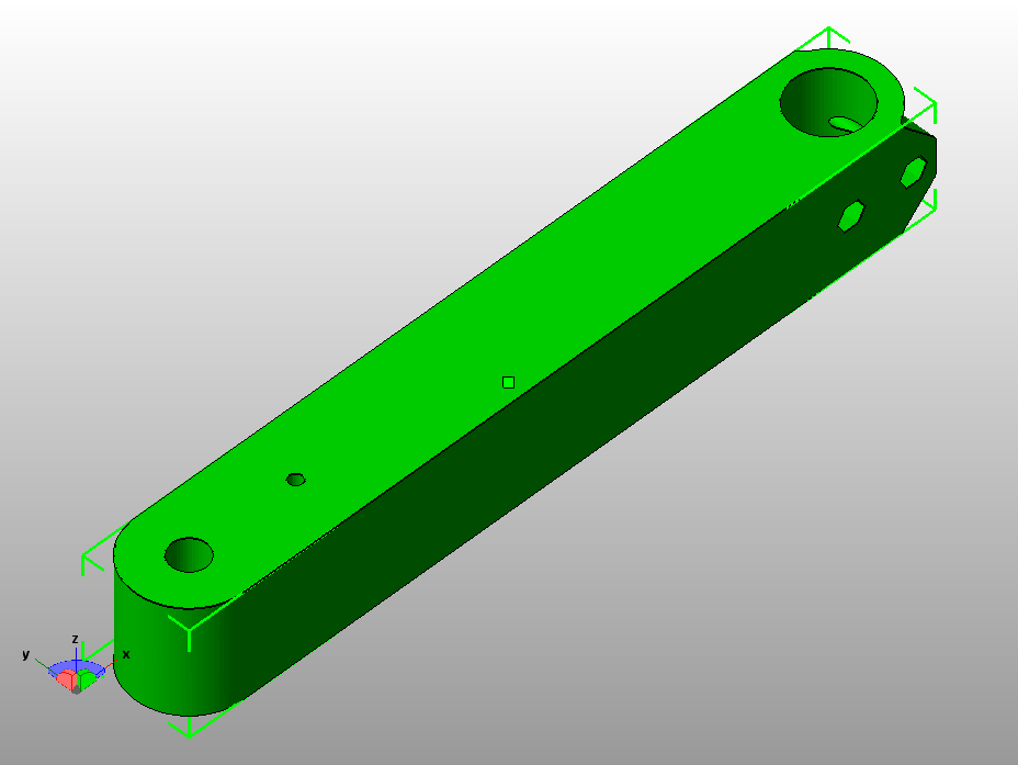
Working of the XY Arm
Wally Top View and XY-Axis Working
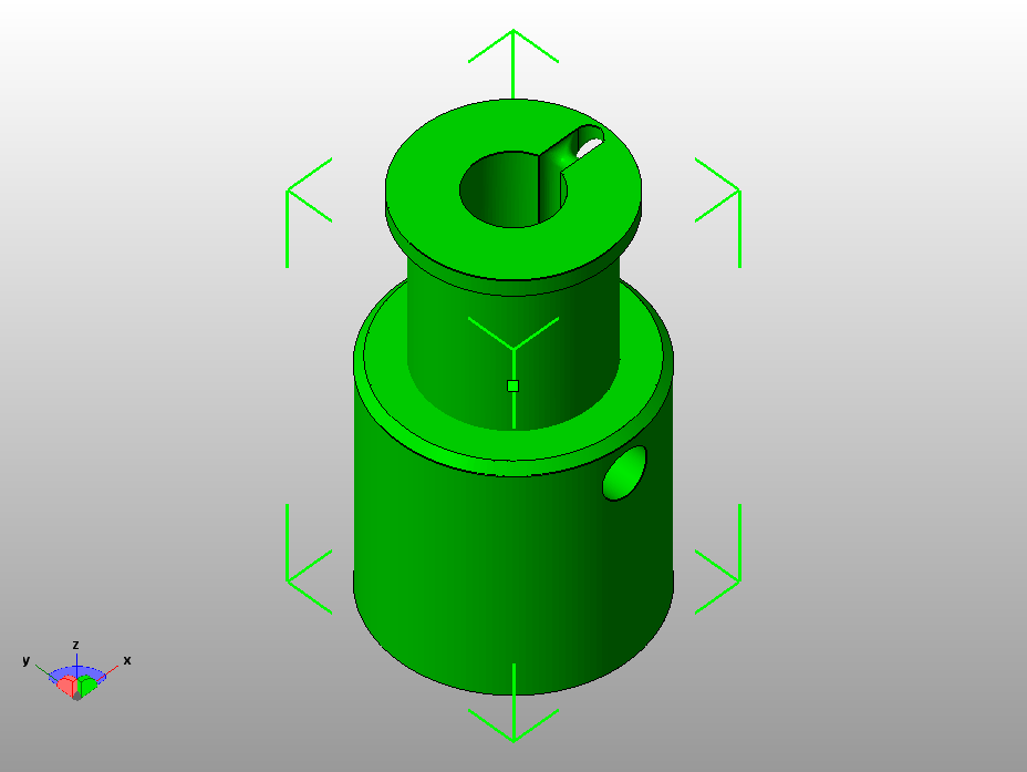
It was the process of controlling the Z-Axis and its movement, as in Wally Z-Axis depends on the movement of the bed not the extruder like in the most of other printers. In wally the extruder only moves in XY-Axis.
Wally Side View - Z-Axis movement
All the important parts for the Z-Axis 3D printed are here.
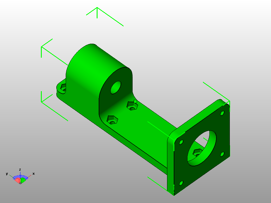
z arm wall bracket.stl, Qty: 2
z idler.stl, Qty: 1
z motor mount.stl, Qty: 1
z pulley holder.stl, Qty: 1
z pulley.stl, Qty: 1
z arm wall bracket.stl, Qty: 2 (Left and Right)
Once the Frame part was done, it was now the time to 3D print all the parts, it was the combined and huge task to print all those parts. We printed them after taking a huge time and the materials.
All the printed parts with the frame
Now it was the time to assemble all the parts
Making the holes, putting pulleys and fixing all parts together
Putting the screws
Putting the screws on the XY axis pulley
The Finaly Result after putting all the components together
The group meeting exploring further functionality
Task division for this week.
over the past few years numerous hardware/software platforms have appearead for 3d printing. Here we present a brief of the most common hardware / software platforms.
Replicating Rapid prototyper (RepRap) project was founded about a decade ago and this project has evolved massively with world wide interest of enthausiasts. Over time this platform has matured into very stable (feature rich) 3D printers which cost less than 500 USD. In market there exist several varients of freely available software and hardware. Two of the most popular software (firmware) and hardware we came across are listed below:
| Software |  |
|
| Hardware |
The picture is pretty much self explainatory.
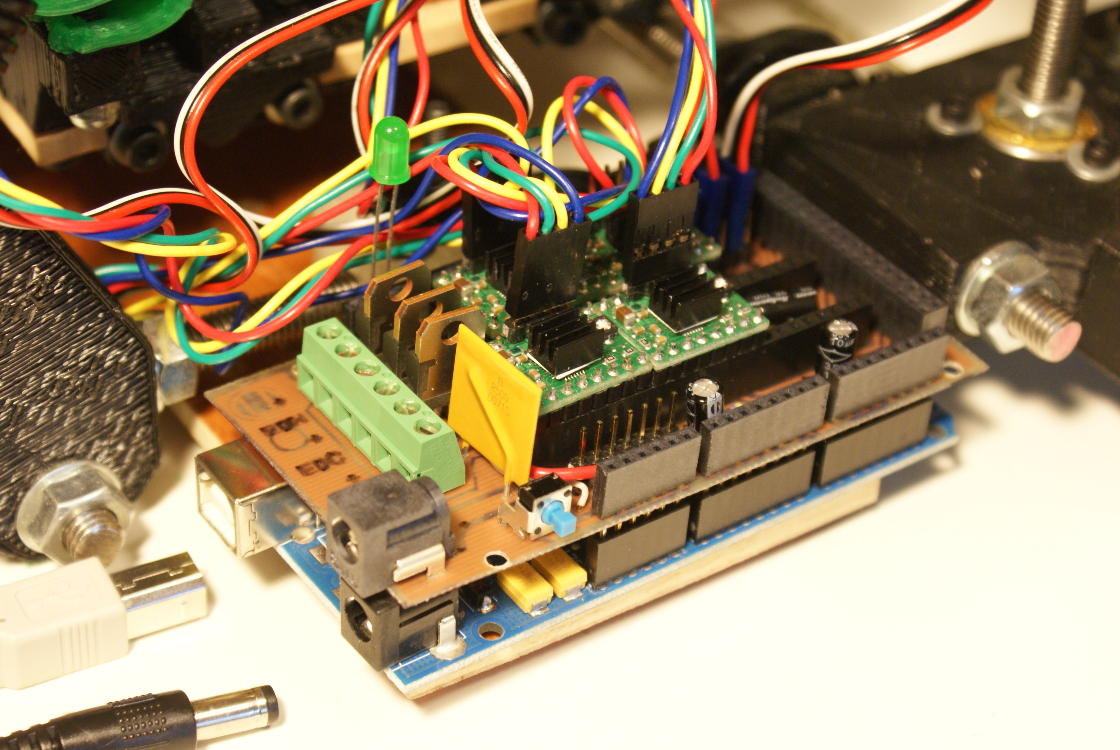
RepRap Arduino Mega Pololu Shield, or RAMPS for short. It is designed to fit the entire electronics needed for a RepRap in one small package for low cost. RAMPS interfaces directly onto an Arduino Mega with the powerful Arduino MEGA platform and has plenty room for expansion. The modular design includes plug in stepper drivers and extruder control electronics on an Arduino MEGA shield for easy service, part replacement, upgradability and expansion. Additionally, a number of Arduino expansion boards can be added to the system as long as the main RAMPS board is kept to the top of the stack. The useful user manual for RAMPS is available here.
RAMPS Circuit
RAMBo (RepRap Arduino-compatible Mother Board) is an all in one RAMPS class motherboard targeting convenience, reliability, and performance.
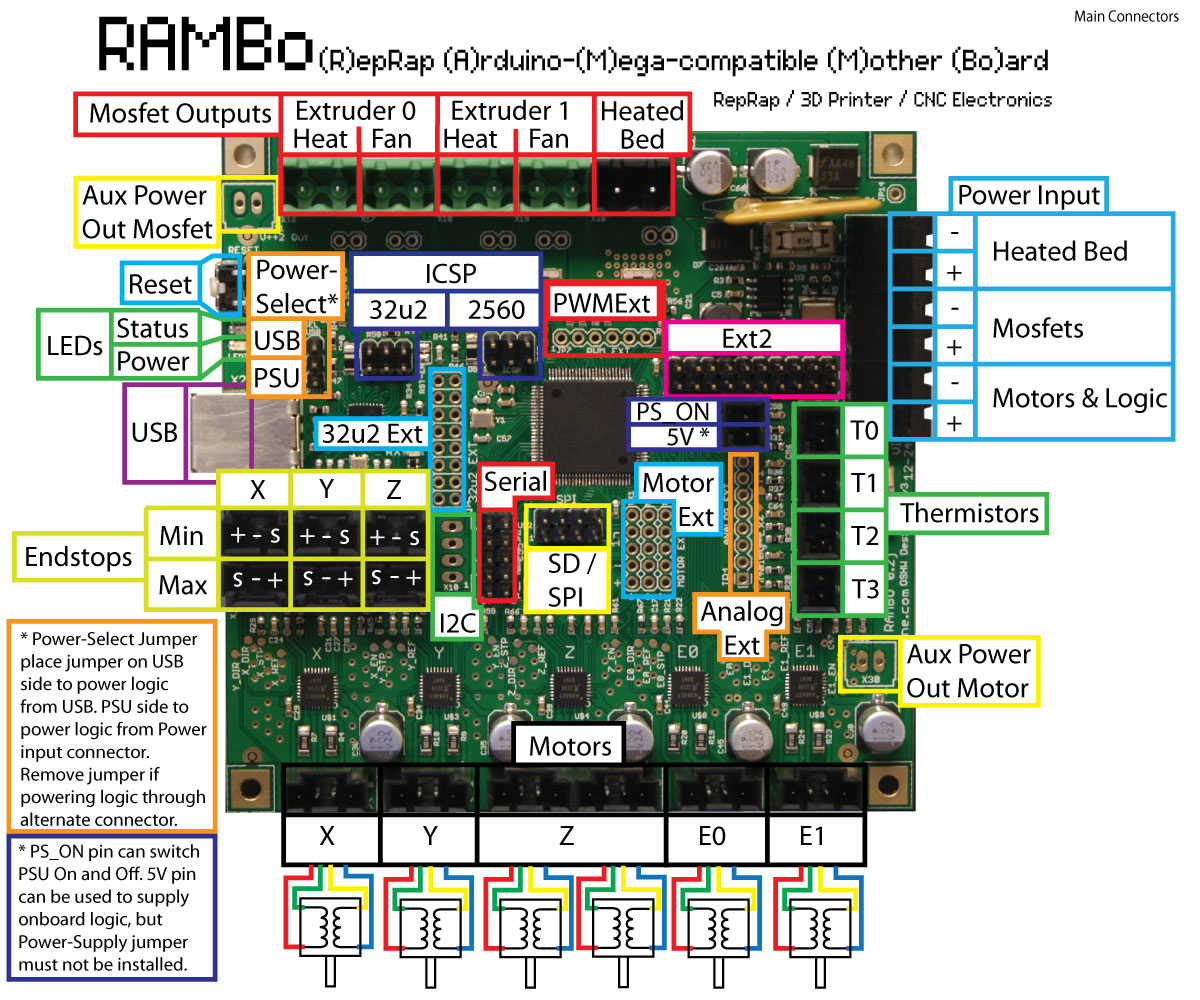
RAMBo Circuit

Repetier-Firmware is a firmware for RepRap like 3d-printer powered with an arduino compatible controller. This firmware is a nearly complete rewrite of the sprinter firmware by kliment which based on Tonokip RepRap firmware rewrite based off of Hydra-mmm firmware. Some ideas were also taken from Teacup, Grbl and Marlin.
Repetier also provides a very handy tool Repetier Host this tool is a ideal platform of basic control and caliberation of the system. This software interfaces directly with the Arduino Mega board through USB interface allowing us to retrieve sensor information and pass G-code scripts. We found the following youtube tutorial very useful to this end.Repetier Host G-Code Tutorial
Marlin is firmware for RepRap single-processor electronics, supporting RAMPS, RAMBo, Ultimaker, BQ, and several other Arduino-based 3D printers. It supports printing over USB or from SD cards with folders, and uses lookahead trajectory planning. Marlin is licensed under the GNU GPL v3 or later. It is based on Sprinter firmware, licensed under GPL v2 or later.
The bill of materials of electronic components necessary for the Wally project is listed here.Typical Circuit Diagram
We started putting together the power supply, stepper motor and interconnection with RAMPs hardware. A good user manual is avaliable at reprap website . After double checking all connections we powered up the circuit.
The next step was to download the updated marlin firmware from HERE
We also had to study in details the marlin framework to be able to configure the board to operate the stepper motors and hot-end, endstops and thermal sensor information. We took help from the following youtube tutorial.Merlin Framework Setup Tutorial
As this toturial described when we open the marlin project in arduino platform, it contains multitude of files, however only configuration.h should be modified for setting up the system. Most of the features can be activated/deactivated by simply commenting/uncommenting the code.
Our modified configuration file is available HERE .
Once all the cables were connected we were in a position to powerup the circuit. The next and most important thing was to caliberate the system. Using default feeds and speeds values from firmware or taking values from any internet directly would not work and we had determine them through simple calculations, trial and error.
Once we got going , we had to write a simple G-code script to test our system. Tomas looked up on the reprap and created this list of important g-code commands which we utilized in our subsequent test scripts.
| Command | Explanation |
|---|---|
| M303 E0 S200 C8 | This will heat the first nozzle (E0), and cycle around the target temperature 8 times (C8) at the given temperature (S200) and return values for P I and D |
| M301 Pxx.xx Ix.xx Dxxx.xx | The Kp, Ki, and Kd values can be entered with |
| M500 | Save the changes |
| G1 Xnnn Ynnn Znnn Ennn Fnnn Snnn | feedrate per minute of the move between the starting point and ending point |
| G28 | Move to Origin (Home) |
| G21 | Set Units to Millimeters |
| G90 | Set to Absolute Positioning |
| G91 | Set to Relative Positioning |
| G92 | Set Position |
| M0 | Stop |
| M17 | Enable/Power all stepper motors |
| M18 | Disable all stepper motors |
| M82 | Set extruder to absolute mode |
| M92 | Set axis_steps_per_unit |
| M104 | Set Extruder Temperature |
| M105 | Get Extruder Temperature |
| M108 | Set Extruder Speed |
| M109 | Set Extruder Temperature and Wait |
| M114 | Get Current Position |
| M115 | Get Firmware Version and Capabilities |
| M117 | Hello World:print |
| M201 | Set max printing acceleration |
| M203 | Set maximum feedrate |
| M208 | Set axis max travel |
| M300 | Play beep sound |
| M360 | Report firmware configuration |
| M550 | Set Name |
Results of simple G-Code script
Normally, linear 3D printers don't need any G-Code preprocessing, because the z-axis is either static or the extruder moves linearly in the z direction. But in case of the Wally, the bed moves in an arc. So we need compensate for this curvelinear trajectory. Luckily there exist a python script which can compensate these effects.
Results of simple G-Code script
There are many specific commands provided in the Wally G-Code preprocessor, some important of those are explained here.
These are the bed caliberation points on certain height the value of x, y and z, as the Wally moves the bed in arc so we had to take into account this movements.
Results of simple G-Code script
For the wally segmentizer to generate accurate code it requires several parameters from the hardware setup. Some of the parameters which we configured listed here:
There are few commands which are important to be explained here:
The modified preprocessing file considered our printer can be here found here.
Once the modified code is availabe is really makes sense to simulate the code using any of the numerous g-code simulation and analysis softwares to validate the operations because (as in our case) if g-code preprocessor has not been carefully configured the modified g-code may veer completely off course. For a large g-code file it may not be possible to located anamolies without exhasustive review. We found following gcode analyzers.
To improve the usefulness of our system we decided to connect wally with a remote computer using octaprint platform. This platform is webserver application running on Raspberry Pi which is connected to a RepRap printer through USB interface. Through this application we can load jobs to a printer remotely and manage/monitor it's performace from a remote location.
We found very good youtube tutorial here
Network Tutorial
Electrical Connections to Raspberry Pi.
Login screen
Access to Raspberry pi from windows network.
Access to Raspberry pi from windows network.